Nissan Ariya: System
- Electric Power Train System
- Air Conditioner Control
- Can Communication
- Charge Port Control
- Ev System Start up Control
- High Voltage Power Supply Control
- Li-Ion Battery Charge Control
- Motor Power Control
- Motor Regeneration Control
- Awd System
- Power Cut Off Control
- Ev System Warning
- Power Limitation Warning
- Shift P Warning Display
- Awd Torque Display
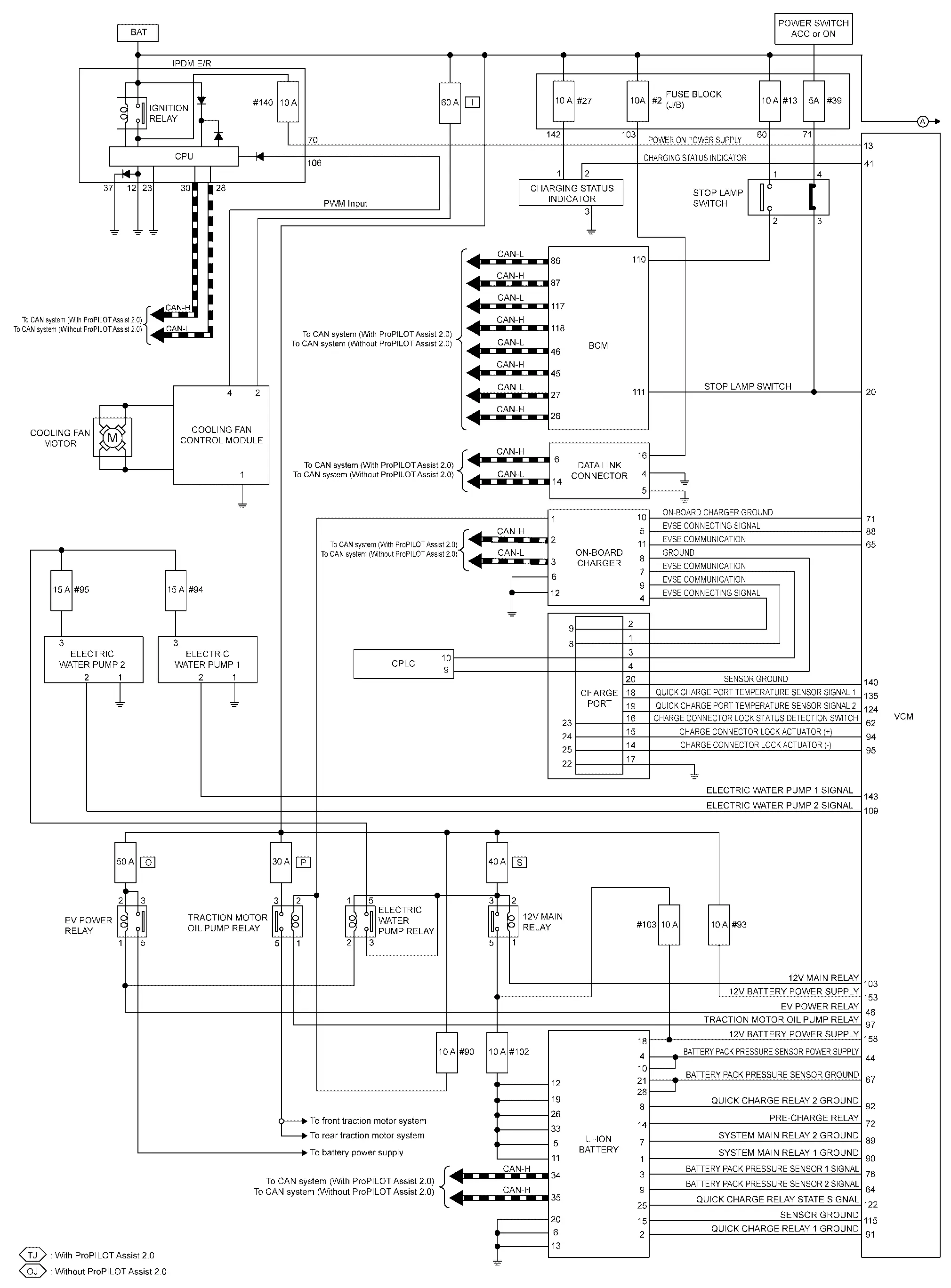
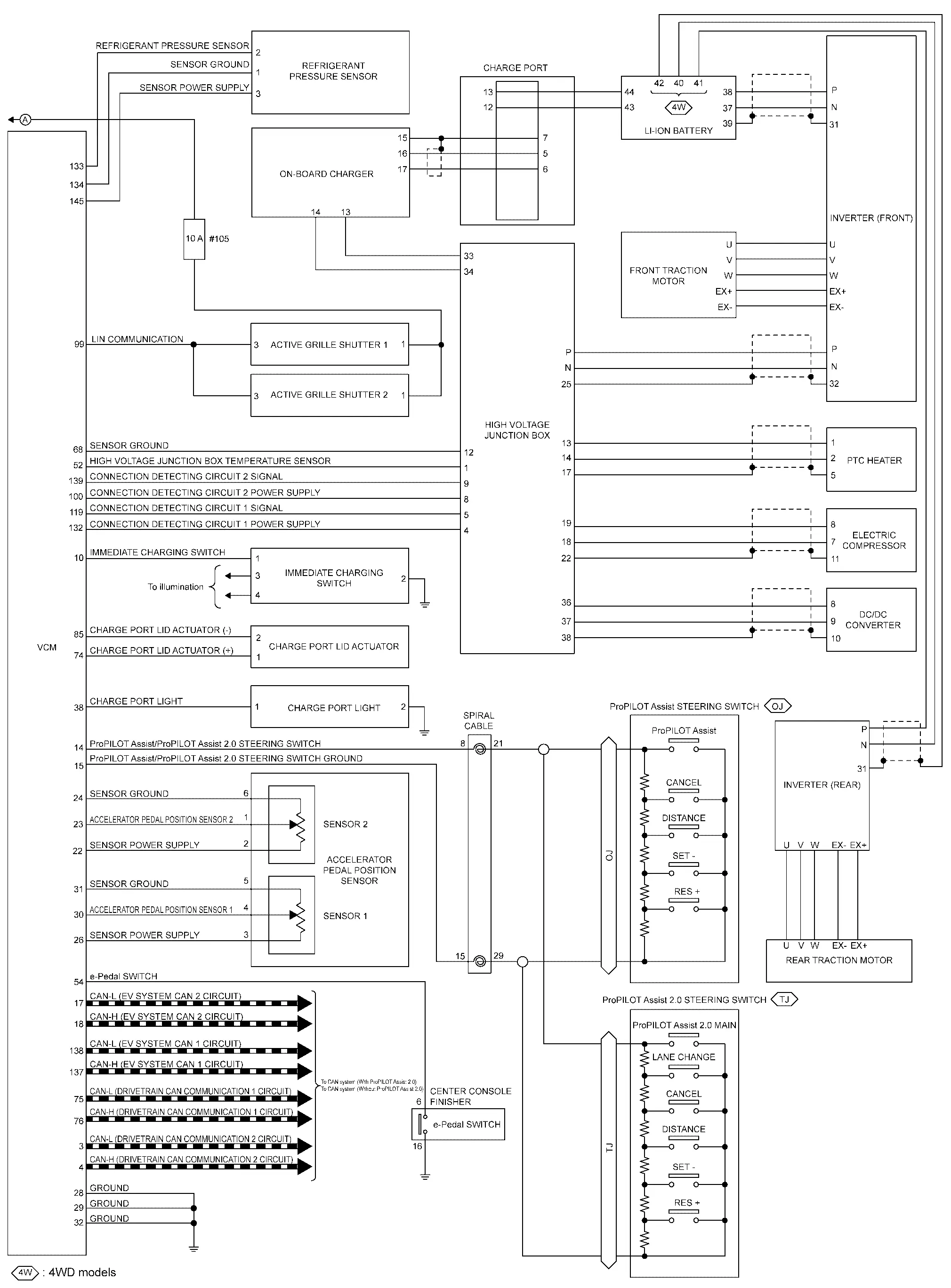
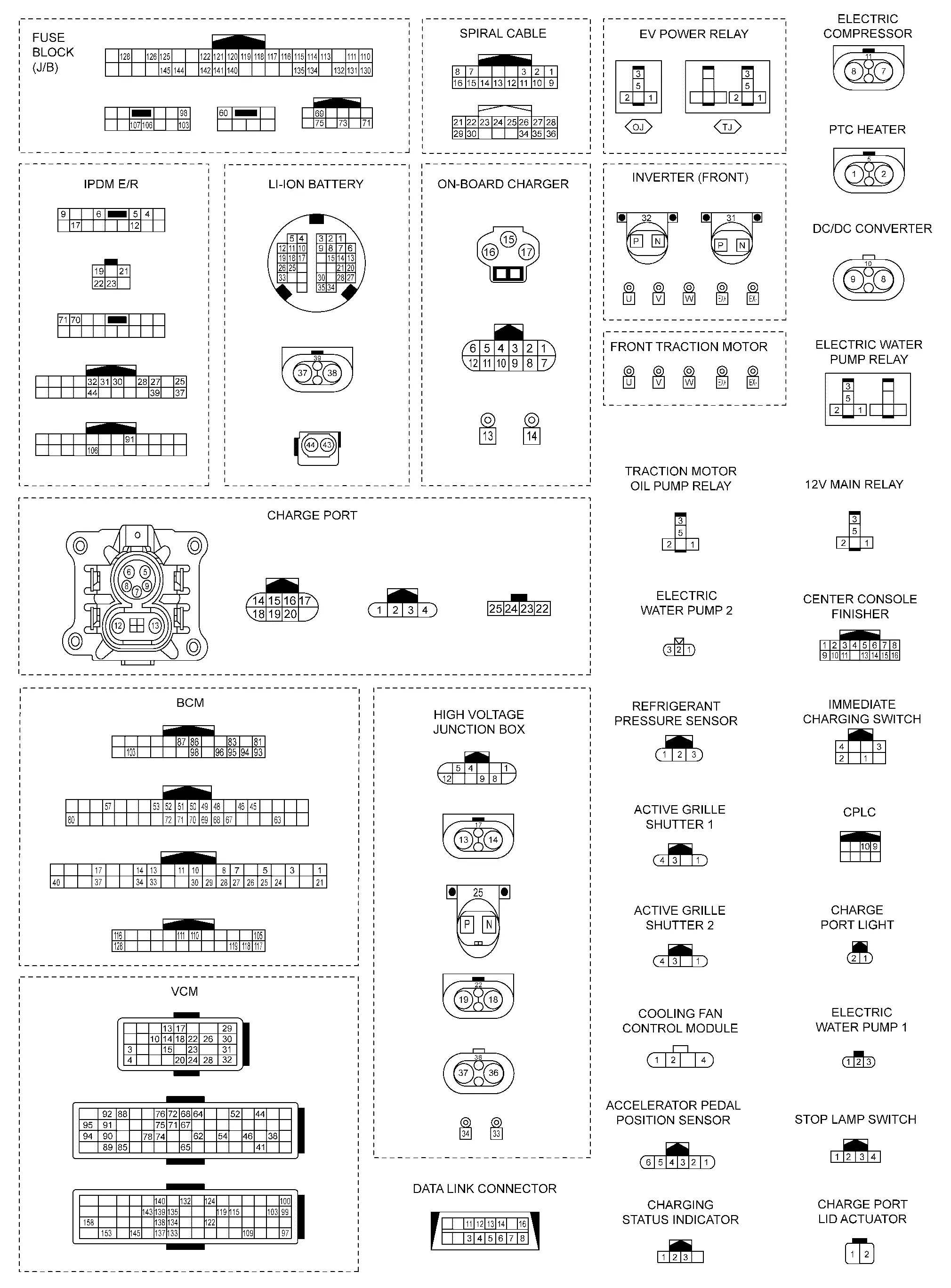
Electric Power Train System Nissan Ariya: FE0
System Description
CONTROL OUTLINE
EV requires all electric power source for the system operation.
The power charged in the Li-ion battery is supplied as high-voltage direct current to the high-voltage system. Meanwhile the power is converted by the DC/DC converter and supplied to the 12 V power system.
VCM judges the vehicle status from various information and performs various EV system controls in a comprehensive manner.
Main Control Contents of VCM
| Control | Reference |
|---|---|
| EV system start up control | Refer to System Description. |
| High voltage power supply control | Refer to System Description. |
| Power cut off control | Refer to System Description. |
| Motor power control | Refer to System Description. |
| Motor regeneration control | Refer to System Description. |
| AWD system | Refer to System Description. |
| Air conditioner control | Refer to System Description. |
| Li-ion battery charge control | Refer to System Description. |
| Charge port control | Refer to System Description. |
| Motor regeneration control | Refer to System Description. |
| MAC (Message Authentication Code) |
MAC (Message Authentication Code) is a function that prevents unauthorized communication from other than the ECU with MAC function by secure authentication communication. VCM can write a MAC key required for communication between the ECUs and perform MAC diagnosis. |
Circuit Diagram
Fail-safe
Fail-safe pattern:
-
Pattern A: Restart is prohibited
-
Pattern B: Traction motor output is limited
-
Pattern C: Quick charge is prohibited
-
Pattern D: Normal charge is prohibited
-
Pattern E: Traction motor output is cut
-
Pattern F: High-voltage system is normally stopped
-
Pattern G: High-voltage system is suddenly stopped
-
Pattern H: A/C control is stopped
FAIL-SAFE LIST
x: applicable
| DTC code | Type | Pattern | Others | |||||||
|---|---|---|---|---|---|---|---|---|---|---|
| A | B | C | D | E | F | G | H | |||
| P0000 | 00 | × | × | × | ||||||
| P0530 | 16 | × | ||||||||
| P0560 | 61 | × | × | × | × | × | × | × | ||
| P0641 | 16,17 | × | × | |||||||
| P0651 | 16,17 | × | × | |||||||
| P0697 | 16,17 | × | × | × | × | × | × | × | ||
| P0AA6 | 23 |
|
||||||||
| P0AE1 | 73 | × | ||||||||
| P0AE2 | 72 | × | ||||||||
| P0AE2 | 73 | × | × | × | ||||||
| P0B33 | 63 | × | ||||||||
| P0CA6 | 19 | × | ||||||||
| P0D0A | 11,12,13 | × | ||||||||
| P0D11 | 11,12,13 | × | ||||||||
| P1001 | 78 | ×(Nissan Ariya vehicle stopped) | ||||||||
| P102C | 01 | × | ||||||||
| P1033 | 11 | × | ||||||||
| P1035 | 49 | × | × | × | × | × | × | × | ||
| P104B | 16,17 | × | ||||||||
| P104C | 16,17 | × | ||||||||
| P12A8 | 08 | Cruse control (ProPILOT Assist/ProPILOT Assist 2.0) operation prohibited | ||||||||
| P1596 | 96 | ×(Nissan Ariya vehicle stopped) | ×(vehicle stopped) | |||||||
| P1597 | F1 | ×(Nissan Ariya vehicle stopped) | ||||||||
| P159D | 23 | × | ||||||||
| P15A6 | 13 | × | × | |||||||
| P15A7 | 31 | × | × | |||||||
| P15A9 | 24 | × | × | |||||||
| P15A9 | 2F | × | ||||||||
| P15AA | 73 | × | × | |||||||
| P15BA | 72 | × | × | |||||||
| P15BE | 96 | ×(Nissan Ariya vehicle stopped) | ||||||||
| P15BF | 96 | ×(Nissan Ariya vehicle stopped) | ×(vehicle stopped) | |||||||
| P15C5 | 78 | ×(Nissan Ariya vehicle stopped) | ||||||||
| P15D3 | 78 | ×(Nissan Ariya vehicle stopped) | ||||||||
| P15FA | 11,12,13 | × | × | |||||||
| P15FB | 01 | × | × | |||||||
| P15FE | 16,17 | × | ||||||||
| P15FE | 64 | × | × | |||||||
| P1604 | 72,73 | × | × | |||||||
| P1605 | 63 | × | × | |||||||
| P160C | 04 | × | × | × | ||||||
| P1613 | 49 | × | × | |||||||
| P161C | 49 | × | × | × | × | × | × | × | ||
| P161C | F1 | × | × | × | × | × | × | × | ||
| P161E | 96 | ×(Nissan Ariya vehicle stopped) | ||||||||
| P161F | 96 | ×(Nissan Ariya vehicle stopped) | ||||||||
| P163F | 94 | × | × | |||||||
| P164B | 64 | P range is held or N range is indicated | ||||||||
| P1666 | 72 | × | ||||||||
| P168A | 11 | × | ||||||||
| P168B | 73 | × | × | |||||||
| P168C | 72 | × | ||||||||
| P168D | 11 | × | ||||||||
| P168D | 12,13 | × | ||||||||
| P168D | 72 | × | ||||||||
| P168E | 11 | × | ||||||||
| P168E | 12,13 | × | ||||||||
| P168E | 73 | × | ||||||||
| P1692 | 19 | × | ||||||||
| P1693 | 49,87 | × | × | × | ||||||
| P1694 | 49,87 | × | × | × | ||||||
| P1695 | 96 | × | ||||||||
| P1728 | 19 | × | ||||||||
| P1729 | 98 | × | ||||||||
| P3101 | 61,62 | × | ||||||||
| P3194 | 00,87 | Cruse control (ProPILOT Assist/ProPILOT Assist 2.0) operation prohibited | ||||||||
| U2370 | 94,96 | × | ||||||||
Warning / Indicator / Chime List
Warning lamp/Indicator lamp
| item | design | Reference |
|---|---|---|
| 12V battery charge warning lamp |  |
For layout, Refer to Design. |
| For function, Refer to 12V Battery Charge Warning Lamp. | ||
| Ready to drive indicator lamp |  |
For layout, Refer to Design. |
| For function, Refer to Ready To Drive Indicator Lamp | ||
| Power limitation indicator lamp |  |
For layout, Refer to Design. |
| For function, Refer to Power Limitation Indicator Lamp | ||
| EV system warning lamp |  |
For layout, Refer to Design. |
| For function, Refer to EV System Warning Lamp |
Warning chime
| item | Reference |
|---|---|
| Shift P warning buzzer | Refer to Shift P Warning Buzzer. |
Warning / Indicator (vehicle information display)
| item | Reference |
|---|---|
| Power limitation warning | Refer to System Description. |
| EV system warning | Refer to System Description. |
| Shift P warning display | Refer to System Description. |
| AWD torque display | Refer to System Description. |
Air Conditioner Control Nissan Ariya
System Description
SYSTEM DIAGRAM
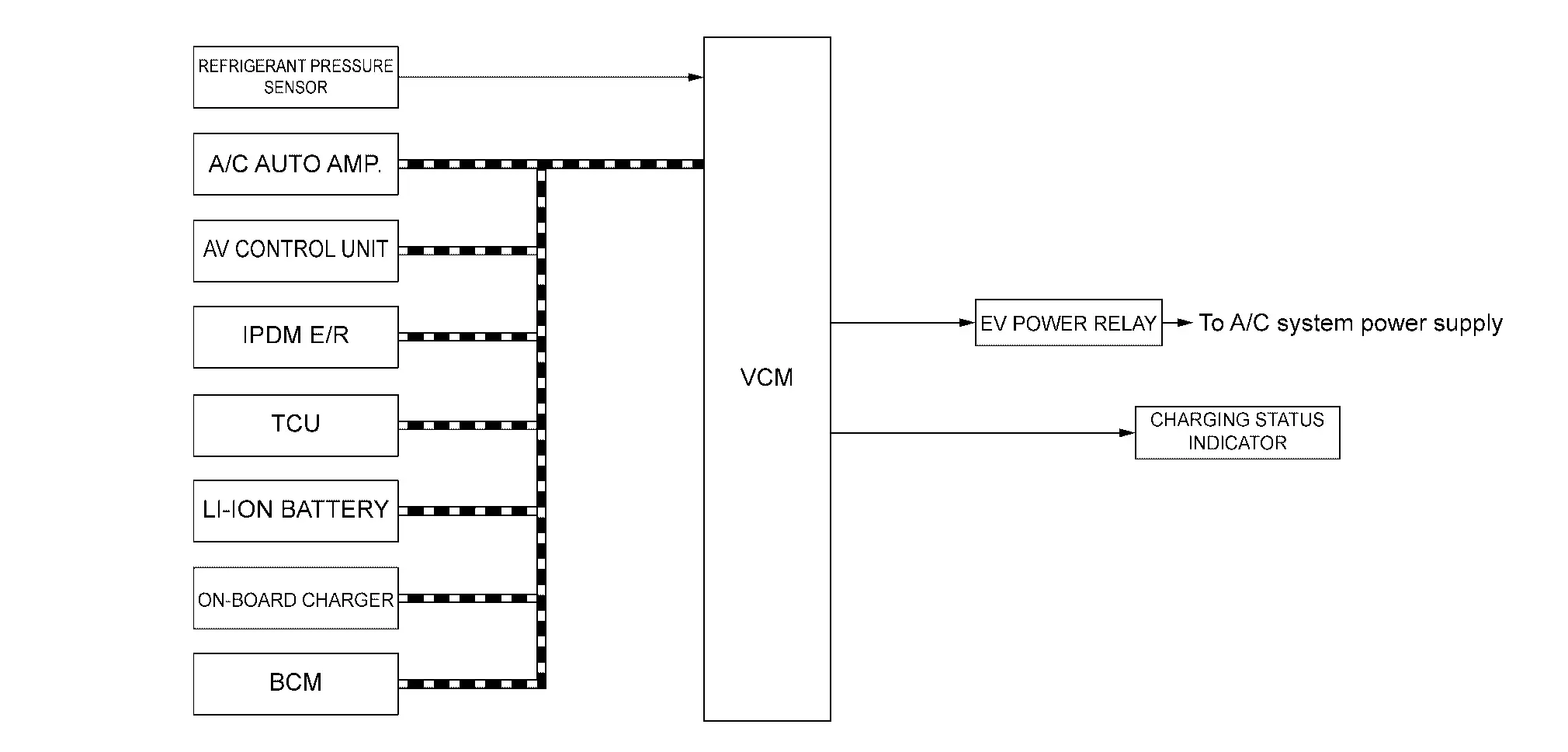
| Component parts | Function |
|---|---|
| IPDM E/R |
|
| On-board charger | EVSE connection signal is transmitted to VCM |
| TCU |
The following signals are transmitted to BCM
|
| AV control unit | Timer A/C set signal is transmitted to BCM and A/C auto Amp. |
| BCM |
|
| Li-ion battery controller | HV battery charge level signal to the VCM. |
| A/C auto amp. |
|
| Charging status indicator | Charge state signal is received from VCM |
| VCM | Refer to Component Description. |
| EV power relay | Refer to Component Description. |
| Refrigerant pressure sensor | Refer to Component Description. |
DESCRIPTION
In EV, the EV power relay is controlled by VCM so that the air conditioner system can be operated even when the power switch such as timer air conditioner, air conditioner before getting in, and deice control is turned off.
When VCM determines to need starting the air conditioner system by the driver's operation based on timer air conditioner, air conditioner before getting in, and deice control, VCM turns on the EV power relay and supplies power to the air conditioner system.
In addition, VCM calculates the power that can be used by the air conditioner system from the state of Li-ion battery and the state of the Nissan Ariya vehicle, and transmits it to A / C auto amp.
For more information of A/C control, refer to System Description.
 NOTE:
NOTE:
When the empty lamp of Li-ion battery is turned ON, A/C does not operate.
DESCRIPTION
TIMER A/C CONTROL
-
When the timer of the timer A/C is ON, BCM reaches the set temperature inside the vehicle* by the scheduled departure time* and activates the timer A/C.
-
While operating time of the timer A/C, two hours before the scheduled departure time, BCM sends a wake up request signal to VCM, VCM activates EV system, and A / C auto amp determines the required operating time from 0 to 1 within the time range based on the outside air temperature and the temperature inside the Nissan Ariya vehicle, and send to BCM. BCM calculates the required operation time sent back from the scheduled departure time and determines the timer A/C start time.
-
For more information on the timer A/C control function,
refer to Climate Ctrl. Timer (A/C-Heater Timer).
NOTE:
-
If the power switch is turned on during timer A/C, it switches to normal A/C control.
-
*:The scheduled departure time and the set temperature inside the Nissan Ariya vehicle are set from the display of the display unit of the integrated interface display.
-
When the empty lamp of Li-ion battery is turned ON, A/C is not operated.
-
A/C CONTROL BEFORE GETTIN IN
-
When VCM receives A/C request signal before getting in from TCU, VCM activates A/C for 15 to 60 minutes.
-
For more information of A/C control function before getting in,
refer to Remote Climate Control.
NOTE:
When the power switch is turned on while A/C before getting in is operating, the A/C before getting in ends.
DEICE CONTROL
-
When VCM receives deice request signal from A/C auto amp and is in normal charge mode or quick charge mode, VCM turns on EV power relay and sends deice permission signal (permission) to A/C auto amplifier. A/C auto amp activates deice function upon receiving deice permission signal.
-
If the charge mode ends due to full charge or timer charge end while the deice function is operating, the deice function continues to operate.
NOTE:
When the charge connector is disconnected from the charge port, VCM sends a deice permission signal (prohibited) and the deice function stops.
-
After completing the compressor operation by the deice control function, VCM activates cooling fan based on cooling fan speed request signal received from A/C auto amp.
-
The deice control function may operate even at the initial stage of timer A/C operation.
-
For more information of the deice control function,
refer to Heat Pump System Control.
Can Communication Nissan Ariya SUV
System Description
DESCRIPTION
-
CAN (Controller Area Network) is a serial communication line for real time application. It is an on Nissan Ariya vehicle multiplex communication line with high data communication speed and excellent error detection ability. Many electronic control units are equipped onto a Nissan Ariya vehicle, and each control unit shares information and links with other control units during operation (not independent).
In CAN communication, control units are connected with 2 communication lines (CAN-H line, CAN-L line) allowing a high rate of information transmission with less wiring. Each control unit transmits/receives data but selectively reads required data only.
-
VCM includes a gateway function and communicates signals between the CAN communication circuit and EV system CAN circuit.
-
For CAN communication details, Refer to System Description.
Charge Port Control Nissan Ariya SUV
System Description
SYSTEM DIAGRAM
DESCRIPTION
For charging port control, VCM comprehensively controls the following related to charging according to the Nissan Ariya vehicle status and signals from each switch.
| Control | Description |
|---|---|
| Charge connector lock/unlock control | When the normal charge connector is connected or during normal charging, charge connector is automatically locked and unlocked. |
| Charge port light control | Automatically turns ON/OFF LED lighting inside the charge port. |
| Charge port lock/unlock control | Perform lock /unlock charge port |
CHARGE PORT LOCK / UNLOCK CONTROL
Description
The charging connector lock/unlock control automatically locks the charging connector according to the charging scene to prevent tampering during charging.
The VCM determines lock activation and unlock conditions based on signals such as EVSE connection signals received from EVSE, setting information signal received from combination meters via CAN communication, and door lock status signal from BCM.
When the condition is satisfied, the charging connector lock relay is activated to operate the charging connector lock actuator in the closed or open direction to lock/unlock the normal charging connector.
There are the following types of lock modes.
| Lock mode | Function |
|---|---|
| "LOCK" | When the normal charge connector is connected, charge connector is automatically locked. |
| "AUTO" |
When charge power supply is not detected even charge connector is locked, or charge connector is locked during normal charge. (When charge is completed, charge connector is automatically unlocked.) |
| "UNLOCK" | Charge connector is locked when normal charge connector is connected. Charge connector is unlocked when charge power supply is detected. |
NOTE:
-
To switch the mode, select "Charging connector lock" of the "EV setting" item of the Nissan Ariya vehicle information display in the combination meter.
-
When the normal charge connector is connected and the Nissan Ariya vehicle is in the P range, it will be locked once even if the unlock condition is satisfied.
LOCK OPERATION CONDITION
When the following conditions are satisfied, VCM locks the charge port connector.
"LOCK" mode
-
Select "Charge connector lock" (Vehicle information display): "LOCK" mode
-
Shift position : P range
-
Normal charge connector: Connect (Complete lock)
"AUTO" mode
-
Select "Charge connector lock" (Vehicle information display): "AUTO" mode
-
Shift position : P range
-
Normal charge connector: Connect (Complete lock)
-
When the start normal charge and the charge power supply are not detected
"UNLOCK" mode
-
Select "Charge connector lock" (Vehicle information display): "UNLOCK" mode
-
Shift position : P range
-
Normal charge connector: Connect (Complete lock)
-
When the charge power supply are not detected
"UNLOCK" OPERATION CONDITION
When the following conditions are satisfied, VCM unlocks the charge port connector.
"LOCK" mode
-
When unlock while the door is locked.
-
Select "Charge connector lock" (Nissan Ariya Vehicle information display): "UNLOCK" mode
-
Shift position : Except P range
-
Nissan Ariya Vehicle is READY
"AUTO" mode
-
When unlock while the door is locked.
-
Select "Charge connector lock" (Vehicle information display): "UNLOCK" mode
-
Shift position : Except P range
-
Nissan Ariya Vehicle is READY
-
When the normal charge is completed.
-
When the charge power supply is shut down.
"UNLOCK" mode
-
When unlock while the door is locked.
-
Shift position : Except P range
-
Nissan Ariya Vehicle is READY
-
When the charge power supply is detected. the charge connector is automatically locked again.
CAUTION:
When the charge connector is not disconnected 30 seconds after door unlocked.
OPERATION TIMING CHART
-
"LOCK" MODE
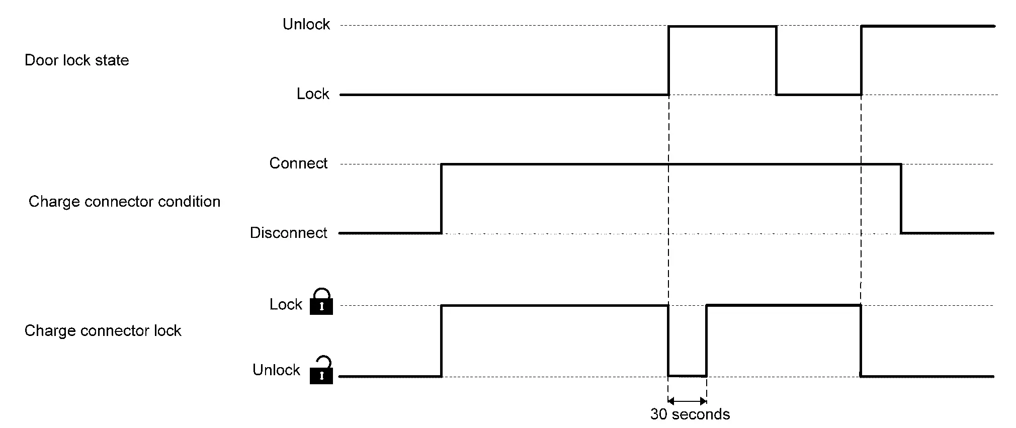
-
"UNLOCK" MODE
OPERATION DESCRIPTION
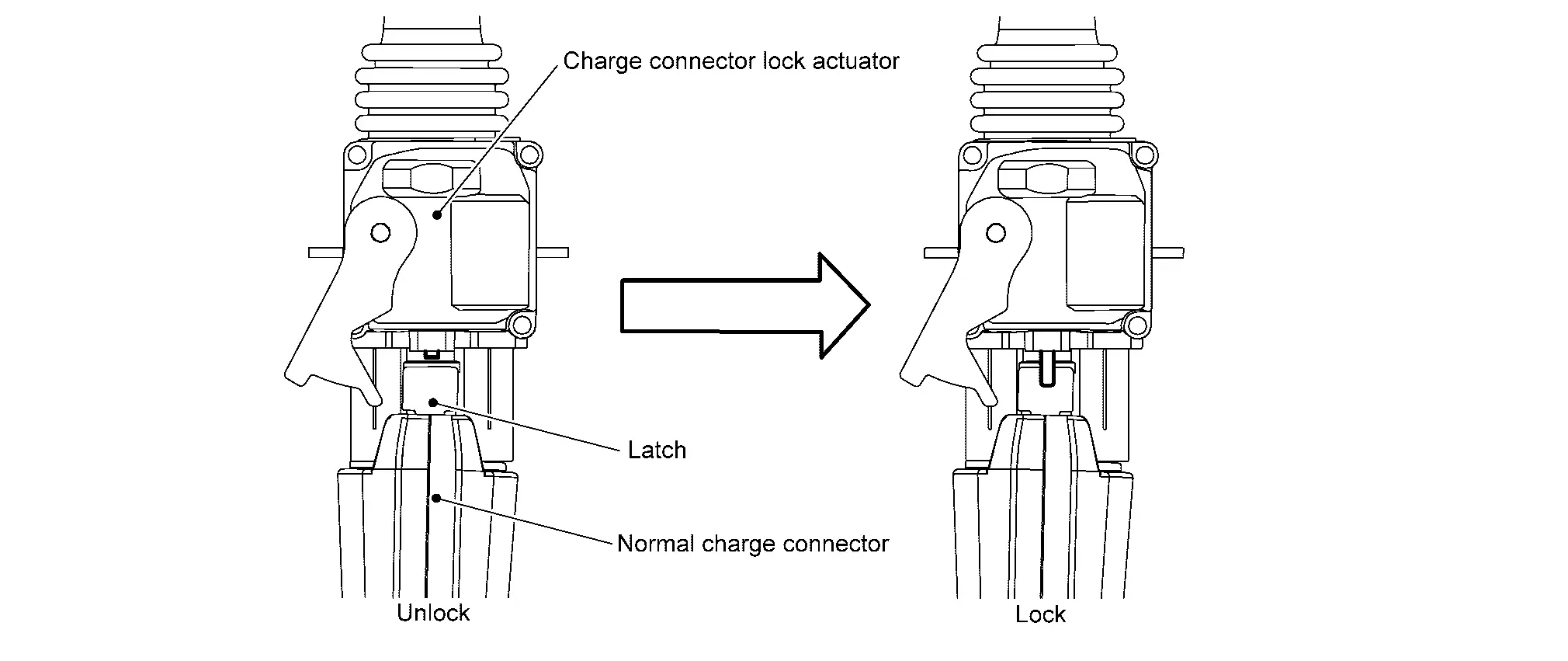
The swing arm of the charge port lock actuator is inserted into the upper part of the latch at the tip of the normal charge connector, and charge connector is locked by restricting the movement of the latch.
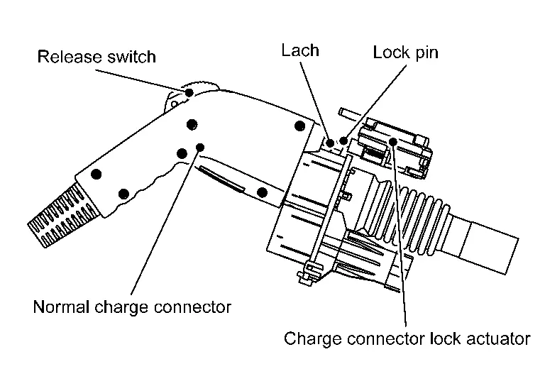
CAUTION:
Release switch cannot be push during LOCK mode.
CAUTION:
When the charge connector lock cannot be unlock, perform the following procedure to unlock manually.
PROCEDURE FOR CHARGE CONNECTOR LOCK / UNLOCK CONTROL ABNORMALITY
When the charge connector lock cannot be unlock automatically, perform the following procedure to unlock manually.
-
Open the hood
-
Operate the lock release lever
 on the back of the charge port base assembly on the normal charge port side in the direction of the arrow in the figure to release the charge port lid lock.
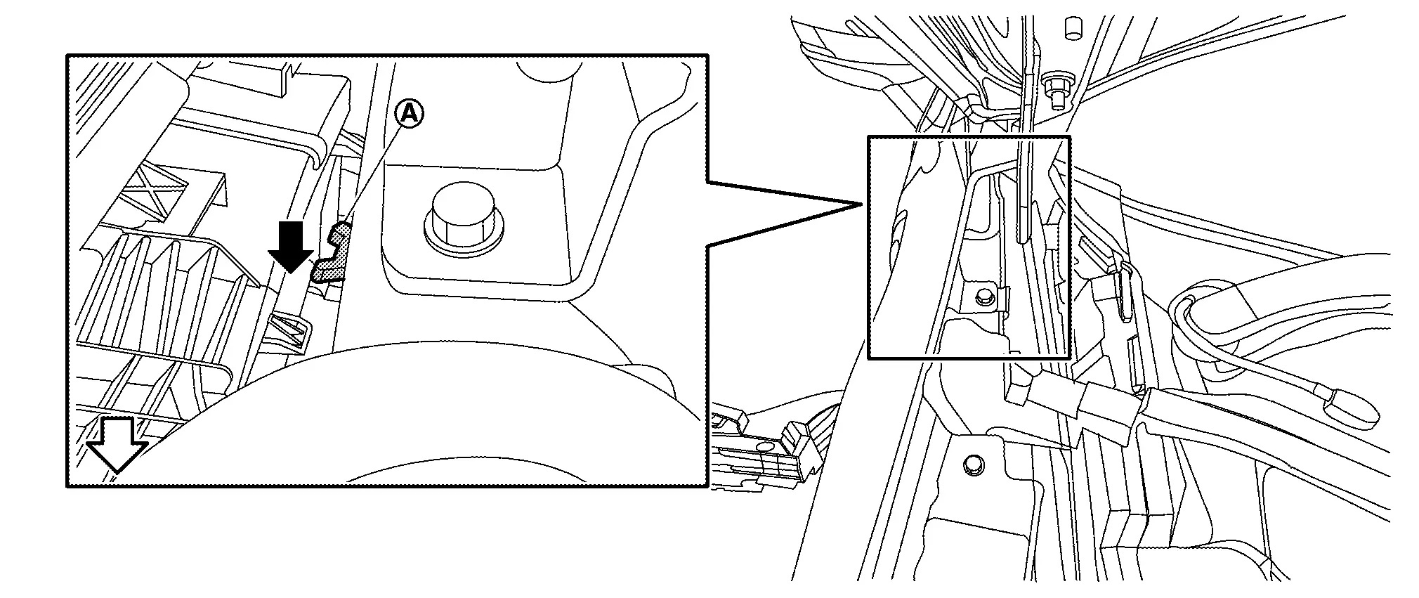

:Nissan Ariya Vehicle front
CHARGE PORT LIGHT CONTROL
DESCRIPTION
The charge port light control which automatically turns ON the LED illumination inside the port to improve workability while charging.
VCM supplies power to the charge port light and turns ON the LED illumination base on vehicle conditions such as charge port connect /disconnect, door lock/ unlick, driver approach/non-approach, etc.
LIGHT ON CONDITION
When the following all conditions are satisfied, VCM turns ON the charge port light.
-
Vehicle is READY
-
Shift position : P position
-
When ON conditions of the following timer table are satisfied.
LIGHT OFF CONDITION
When the following any condition is satisfied, VCM turns OFF the charge port light.
-
Vehicle is READY
-
Shift position : Except P position
-
When the timer time in the following timer table has passed.
NOTE:
The timer time is overwritten at any time with the timer time established later.
CHARGE PORT LIGHT TIMER TABLE
| Control | Description |
|---|---|
| When the charge connector is unlocked | 3 min. |
|
When the charge lid lock is unlocked (When the Nissan Ariya vehicle door lock is unlocked, when entering unlock operation condition at approaching) |
|
| When the door is opened from closed state. | |
| When the charge connector is removed. *1 | 30 sec. |
| When entering auto lock operation condition at getting out from the Nissan Ariya vehicle | |
| When connecting the charge connector | 1.5 sec. |
| When the Nissan Ariya vehicle door is locked during connecting the charge port connector | |
| When the charge connector is locked |
*1:If the charging connector is unplugged without holding the intelligent key, the port light may not turn on.
NOTE:
For unlocking when approaching and auto-locking when getting off, Refer to System Description.
CHARGE PORT LOCK/UNLOCK CONTROL
DESCRIPTION
The VCM receives the door lock status signal from the BCM via CAN communication, activates the charge port lid actuator in conjunction with the door lock / unlock switching, and locks / unlocks the charge port lid.
CHARGE PORT LID LOCK OPERATION CONDITION
When all of the following conditions are satisfied, the VCM locks the charge port lid.
-
When the charge port lid is closed
-
The one of the followings is satisfied.
-
When the Nissan Ariya vehicle door is locked
-
When entering the auto lock operation condition at getting out the Nissan Ariya vehicle.
-
CHARGE PORT LID UNLOCK OPERATION CONDITION
When the following any condition is satisfied, the VCM unlocks the charge port lid.
-
When the vehicle door is unlocked.
-
When entering the unlock operation condition at approaching to the Nissan Ariya vehicle.
NOTE:
-
When the lock cannot be unlocked due to a dead battery or a malfunction of the charge port lid opener actuator. the lock is unlocked manually. Refer to Unlocking.
-
For unlocking when approaching and auto-locking when getting off the Nissan Ariya vehicle refer to System Description.
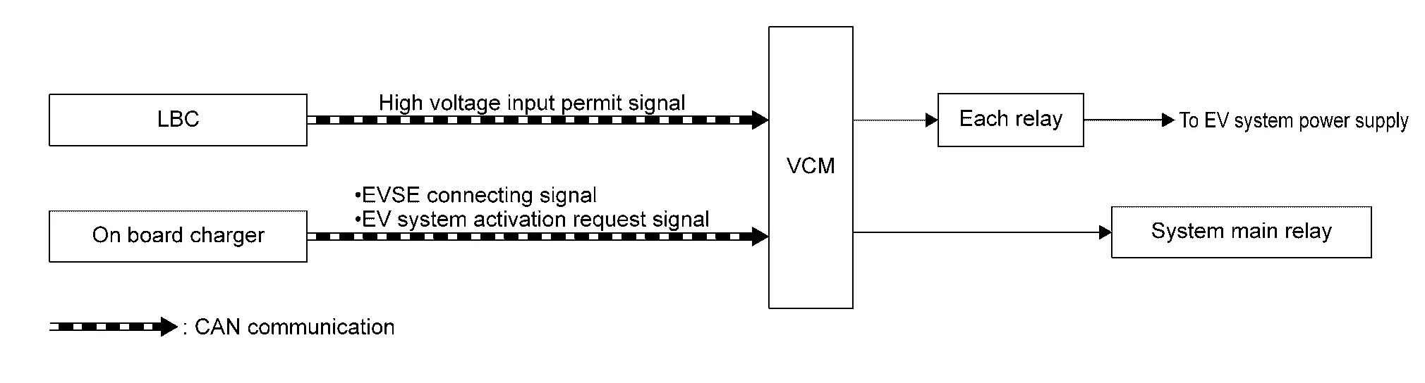
Ev System Start up Control Nissan Ariya SUV
System Description
SYSTEM DIAGRAM
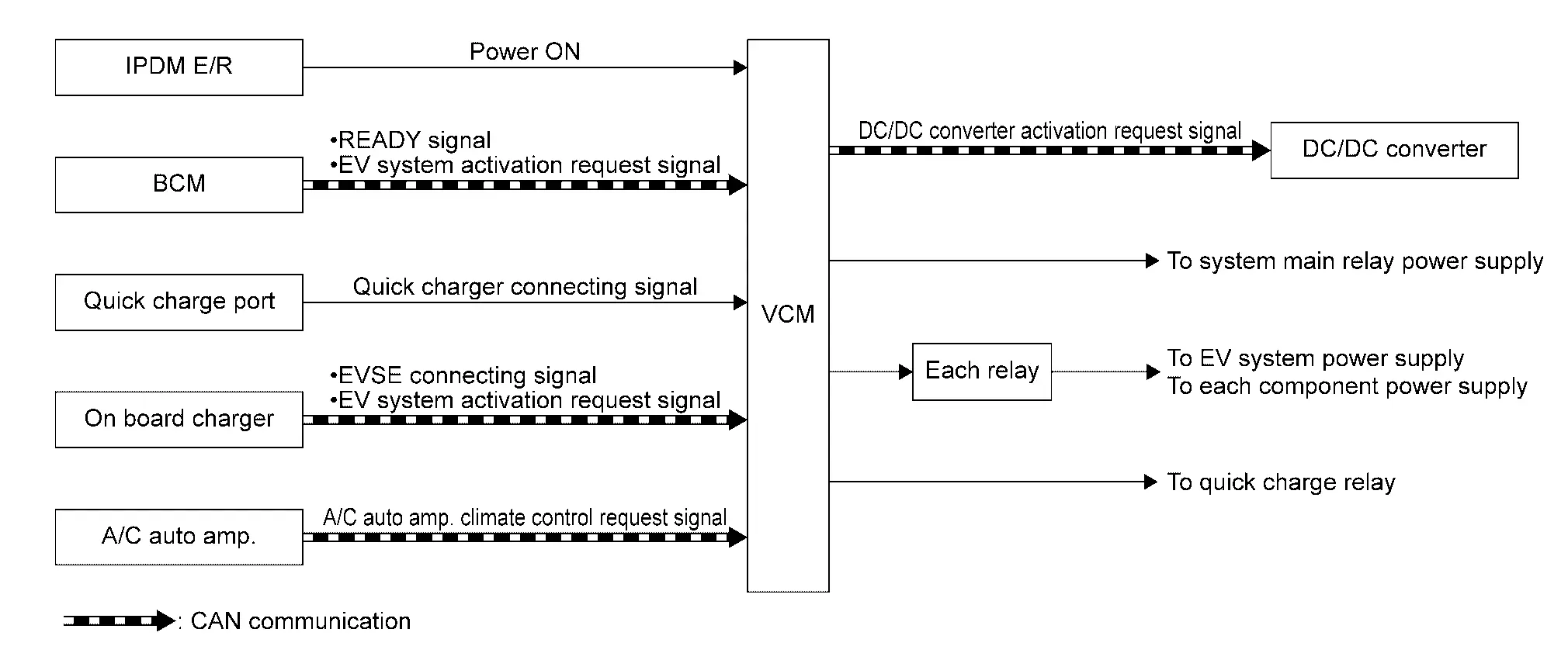
| Component parts | Function |
|---|---|
| IPDM E/R | IPDM E/R transmits the power ON signal to VCM. |
| BCM |
BCM transmits the following signals to VCM
|
| Charge port (quick charge) | Quick charge port transmits the quick charger connecting signal to VCM. |
| On-board charger |
In-Nissan Ariya vehicle charger transmits the following signals to VCM
|
| VCM | Refer to Component Description. |
| A/C auto amp. | A/C auto amp. transmits the cooling request signal to VCM. |
| DC/DC converter | DC/DC receives converter transmits the start up request signal from VCM |
| Each relay | — |
CONTROL DESCRIPTION
VCM judges the operation mode from signals sent by various sensors, switches, and ECUs, and controls the start/stop of the EV system by activating the relays accordingly.
Power Switch ON
When the power supply for power ON is input from the IPDM E/R enters VCM, VCM turns ON each relay to supply power to each ECU and parts of EV system.
READY
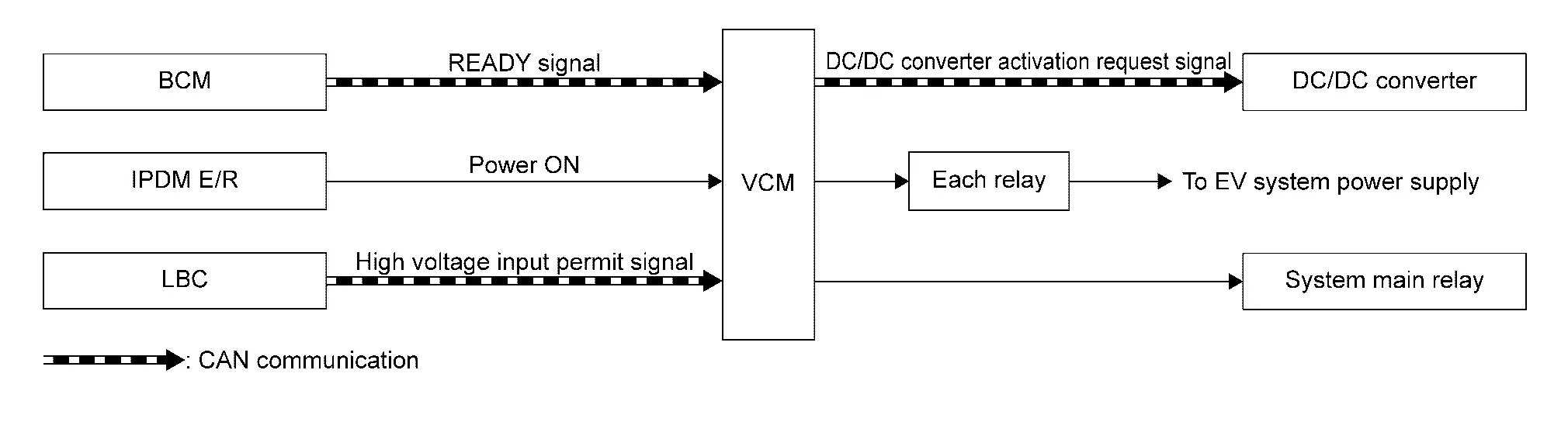
When the driver operates the POWER switch while depressing the brake pedal, VCM turns ON each relay to supply power to each ECU and parts of EV system. Furthermore, VCM supplies power to the system main relay.
NOTE:
VCM inhibits the vehicle is set to READY in following conditions:
-
Charge connector is connected.
-
Li-ion battery remaining energy is too low.
-
Li-ion battery temperature is too low. [ -30°C approx. or less ]
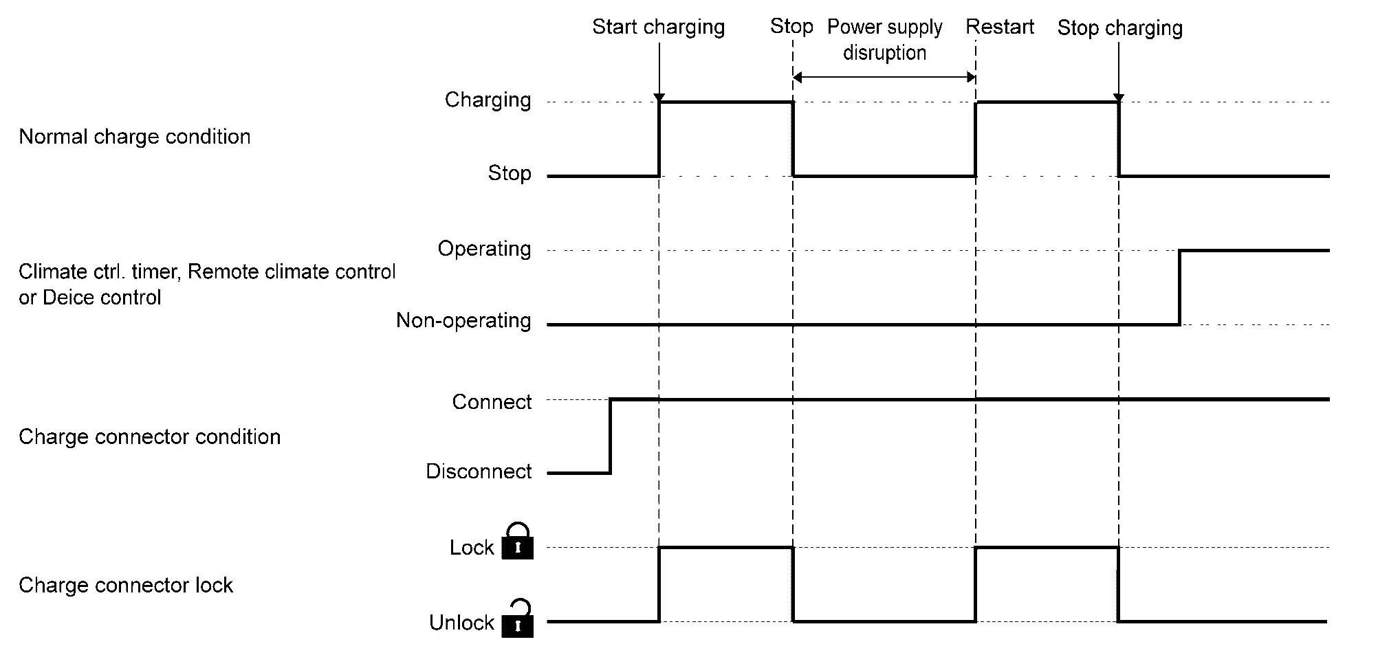
In Normal Charging
If VCM judges that the system is in normal charge mode, VCM turns ON each relay to supply power to each ECU of the EV system. Furthermore, VCM supplies power to the system main relay.
NOTE:
Normal charging does not start with the power switch ON.
In Quick Charging
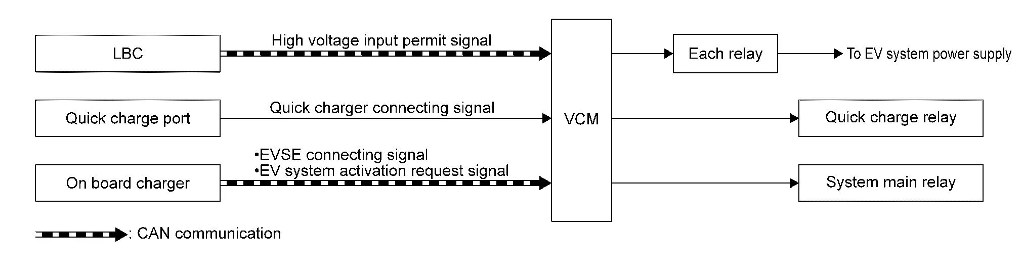
When VCM judges that the system is in quick charge mode, VCM turns ON each relay to supply power to each ECU of the EV system. Furthermore, Furthermore, VCM supplies power to the quick charge relay and the system main relay.
When Air Conditioner Is Operating (Power OFF)
When air conditioner and its timer, etc., are activated before getting into the vehicle, VCM turns ON each relay to start the EV system. VCM also supplies power of the system main relay and starts A/C system.
In 12V Battery Automatic Charging
When VCM judges that the 12V battery requires automatic charging, VCM turns ON each relay to start the EV system. Furthermore, VCM supplies power the system main relay.
High Voltage Power Supply Control Nissan Ariya SUV
System Description
SYSTEM DIAGRAM
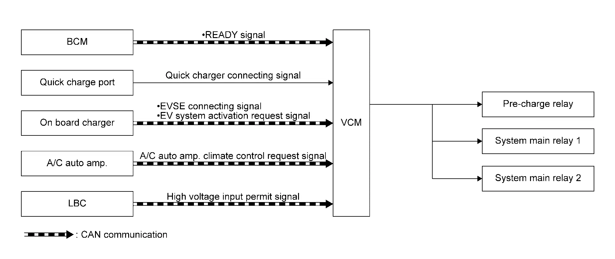
| Component parts | Function |
|---|---|
| BCM | BCM transmits the following signals to VCM. |
| Charge port (quick charge) | Quick charge port transmits the quick charger connecting signal to VCM. |
| On-board charger |
In-Nissan Ariya vehicle charger transmits the following signals to VCM.
|
| A/C auto amp. | A/C auto amp. transmits the cooling request signal to VCM. |
| LBC | LBC transmits high voltage input permit signal to VCM. |
| VCM | Refer to Component Description. |
| Pre-charge relay | Refer to Component Description. |
| System main relay 1 | Refer to Component Description. |
| System main relay 2 | Refer to Component Description. |
DESCRIPTION
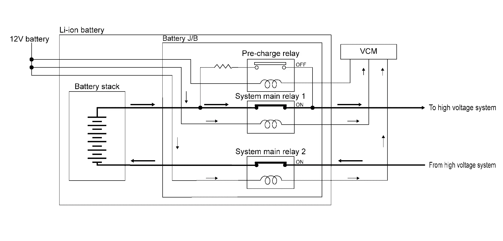
When the driver performs the READY operation or connects the charge cable to a charging port, or when VCM starts according to the timer control and judges the necessity of connecting the high voltage circuit to Li-ion battery, VCM activates system main relay 1, system main relay 2, and the pre-charge relay located inside the Li-ion battery junction box and connects high voltage circuit to Li-ion battery.
Moreover, the high voltage circuit of the EV system has a pre-charge circuit to protect the high voltage circuit from sudden application of high voltage current.
CONTROL FLOW
To connect the high voltage circuit, VCM first activates the pre-charge relay and system main relay 2.
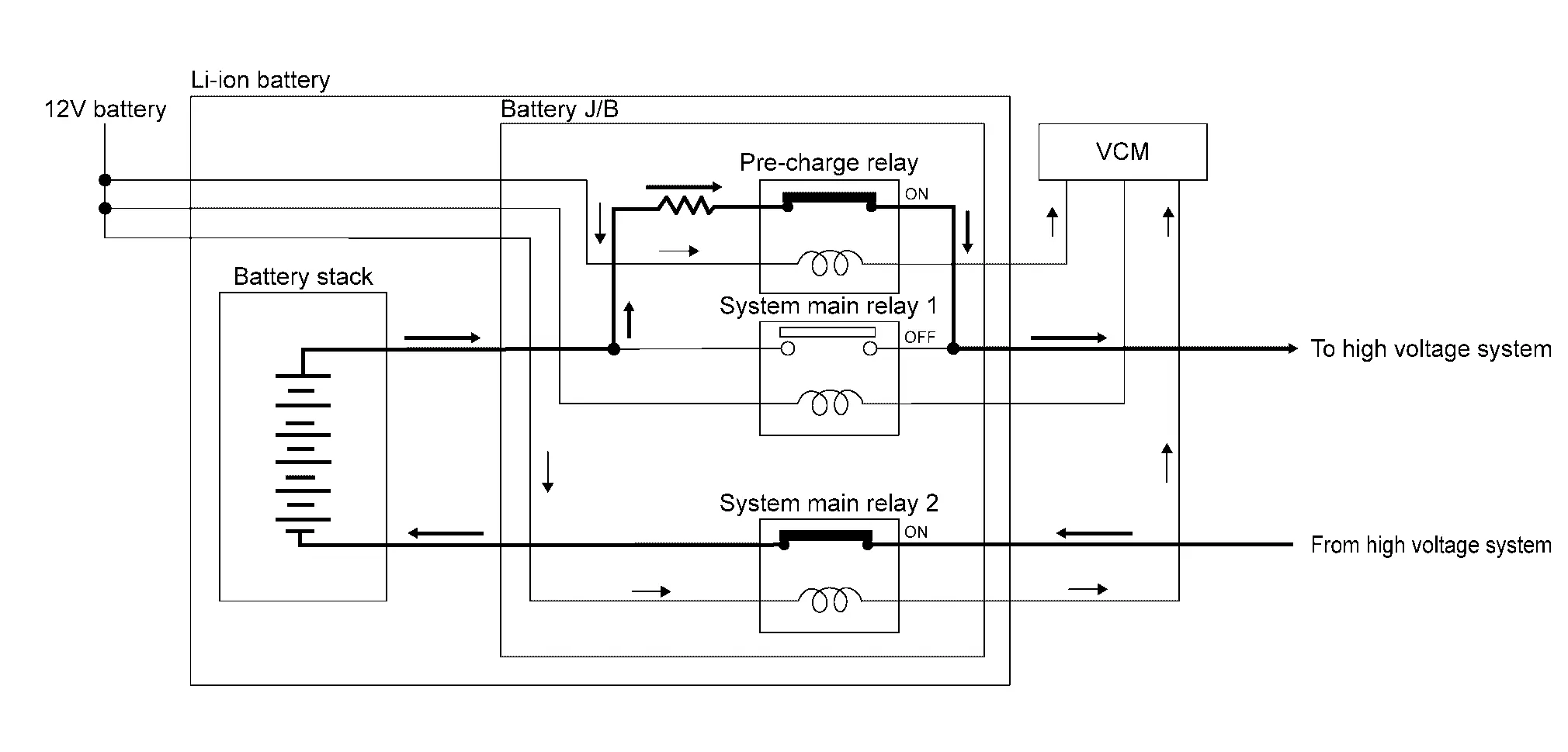
As a result, the high voltage power is supplied to the respective systems via the pre-charge resistor in the pre-charge circuit.
VCM activates the system main relay 1 and deactivates the pre-charge relay. Then, normal power is supplied to the respective systems.
Li-Ion Battery Charge Control Nissan Ariya SUV
System Description
CONTROL OUTLINE
-
Li-ion battery charge is controlled by VCM
-
VCM activates the EV system by connecting the charging connector and performing remote control, and starts charging to the Li-ion battery. The following charge modes are available.
| Methods of charging | Description | |
|---|---|---|
| Li-ion battery charge control | Refer to System Description. | |
| Normal charge | Immediate charge | Refer to System Description. |
| Timer charge | ||
| Remote charge | ||
| Quick charge | Refer to System Description. | |
| Regeneration charge | Refer to System Description. | |
Motor Power Control Nissan Ariya 2026
System Description
2WD models
SYSTEM DIAGRAM
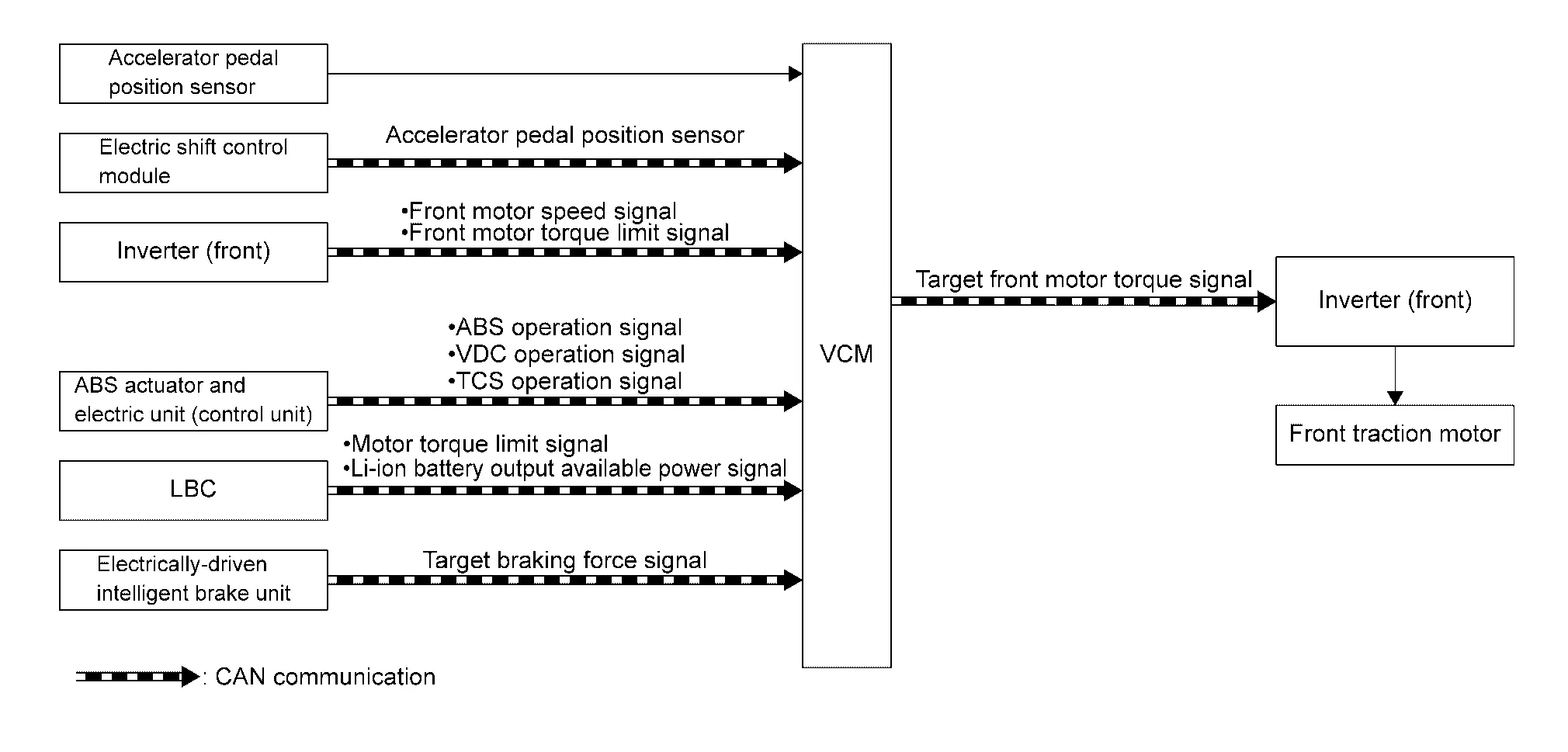
| Component parts | Function |
|---|---|
| Accelerator pedal position sensor | Accelerate pedal position sensor signal is transmitted to VCM |
| Electric shift control module | Electric shift control module transmits shift information to VCM |
| Inverter (front) |
Inverter (front) transmits the following signals to VCM
|
| ABS actuator and electric unit (control unit) |
ABS actuator transmits the following signals to VCM
|
| LBC |
LBC transmits the following signals to VCM
|
| Electrically-driven intelligent brake unit | Electrically-driven intelligent brake unit transmits target braking force signal to VCM. |
| VCM | Refer to Component Description. |
NOTE:
VCM calculates vehicle speed, based on a motor speed.
DESCRIPTION
The EV system generates traction force by converting the direct current from the Li-ion battery to an alternating current by the inverter (front).
VCM calculates target traction force, based on an accelerator pedal position, vehicle speed, and shift position. After that, VCM adds creep force to the calculated target traction force. Moreover, VCM performs torque limit processing according to the torque limit request from each system, determines target front motor torque signal. and transmits it to the inverter (front) via CAN communication. The inverter (front) applies a current to the motor corresponding to the signal and generates traction force.
In addition, VCM always determines whether the creep force is required to output from the vehicle speed and braking force.
For the operation principle of the motor, Refer to System Description.
OUTPUT LIMIT AND OUTPUT STOP REQUEST LIST
| Request ECU | Output limit cause | Power limitation indicator lamp | Condition | |
|---|---|---|---|---|
|
Inverter (front) |
Front traction motor temperature high | ON | When front traction motor or inverter (front) reaches abnormally high temperature | |
| Input power low | ON | When high voltage power supply input to inverter (front) is 270V or less. | ||
| DTC detected | ON | Refer to Fail-safe. | ||
| Li-ion battery controller (LBC) | Li-ion battery remained energy low | ON | When Li-ion battery cell voltage is low | |
| Li-ion battery temperature high | ON | When Li-ion battery reaches abnormally high temperature. | ||
| Li-ion battery temperature low | ON | When Li-ion battery reaches an abnormally low temperature. | ||
| DTC detected | ON | Refer to Fail-safe(66kWh LI-ION BATTERY), Fail-safe(91kWh LI-ION BATTERY). | ||
| Others | ON | When none of the above | ||
| VCM | Accelerator pedal position signal / stop lamp switch signal input error | ON | When accelerator pedal and brake pedal are judged depressing at the same time | |
| Power train system protection function | ON | — | ||
| DTC detected | ON | Refer to Fail-safe. | ||
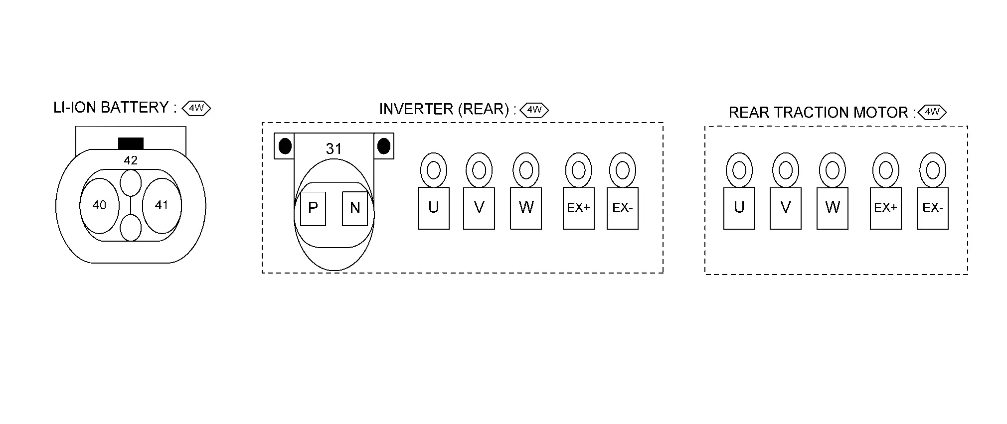
AWD models
SYSTEM DIAGRAM
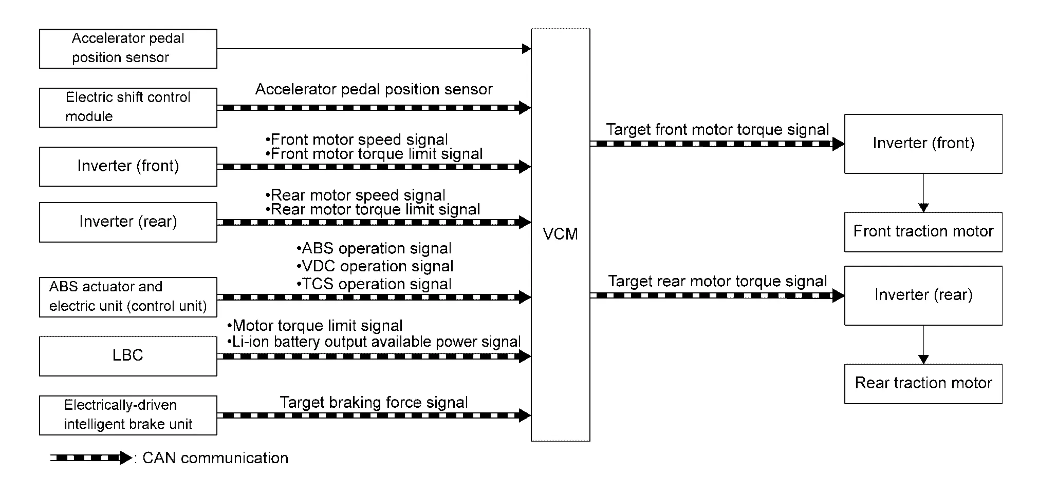
| Component parts | Function |
|---|---|
| Accelerator pedal position sensor | Accelerate pedal position sensor signal is transmitted to VCM |
| Electric shift control module | Electric shift control module transmits shift information to VCM |
| Inverter (front) |
Inverter (front) transmits the following signals to VCM
|
| Inverter (rear) |
Inverter (rear) transmits the following signals to VCM.
|
| ABS actuator and electric unit (control unit) |
ABS actuator transmits the following signals to VCM
|
| LBC |
LBC transmits the following signals to VCM
|
| Electrically-driven intelligent brake unit | Electrically-driven intelligent brake unit transmits target braking force signal to VCM. |
| VCM | Refer to Component Description. |
NOTE:
VCM calculates vehicle speed, based on a motor speed.
DESCRIPTION
The EV system generates traction force by converting the direct current from the Li-ion battery to an alternating current by the inverter (front) and inverter (rear).
VCM calculates target traction force, based on an accelerator pedal position, vehicle speed, and shift position. After that, VCM adds creep force to the calculated target traction force. Moreover, VCM performs torque limit processing according to the torque limit request from each system, determines target motor torque signal. and transmits it to the inverter (front) and inverter (rear) via CAN communication. The inverter (front) and inverter (rear) applies a current to the motor corresponding to the signal and generates traction force.
In addition, VCM always determines whether the creep force is required to output from the vehicle speed and braking force.
For the operation principle of the motor, Refer to System Description(Front traction motor), System Description(Rear traction motor).
OUTPUT LIMIT AND OUTPUT STOP REQUEST LIST
| Request ECU | Output limit cause | Power limitation indicator lamp | Condition | |
|---|---|---|---|---|
| Inverter (front) | Front traction motor temperature high | ON | When front traction motor or inverter (front) reaches abnormally high temperature | |
| Input power low | ON | When high voltage power supply input to inverter (front) is 270V or less. | ||
| DTC detected | ON | Refer to Fail-safe. | ||
| Inverter (rear) | Rear traction motor temperature high | ON | When rear traction motor or inverter (rear) reaches abnormally high temperature | |
| Input power low | ON | When high voltage power supply input to inverter (rear) is 270V or less. | ||
| DTC detected | ON | Refer to Fail-safe. | ||
| Li-ion battery controller (LBC) | Li-ion battery remained energy low | ON | When Li-ion battery cell voltage is low | |
| Li-ion battery temperature high | ON | When Li-ion battery reaches abnormally high temperature. | ||
| Li-ion battery temperature low | ON | When Li-ion battery reaches an abnormally low temperature. | ||
| DTC detected | ON | Refer to Fail-safe(66kWh LI-ION BATTERY), Fail-safe(91kWh LI-ION BATTERY). | ||
| Others | ON | When none of the above | ||
| VCM | Accelerator pedal position signal / stop lamp switch signal input error | ON | When accelerator pedal and brake pedal are judged depressing at the same time | |
| Power train system protection function | ON | — | ||
| DTC detected | ON | Refer to Fail-safe. | ||
Motor Regeneration Control Nissan Ariya first Gen
System Description
2WD models
SYSTEM DIAGRAM
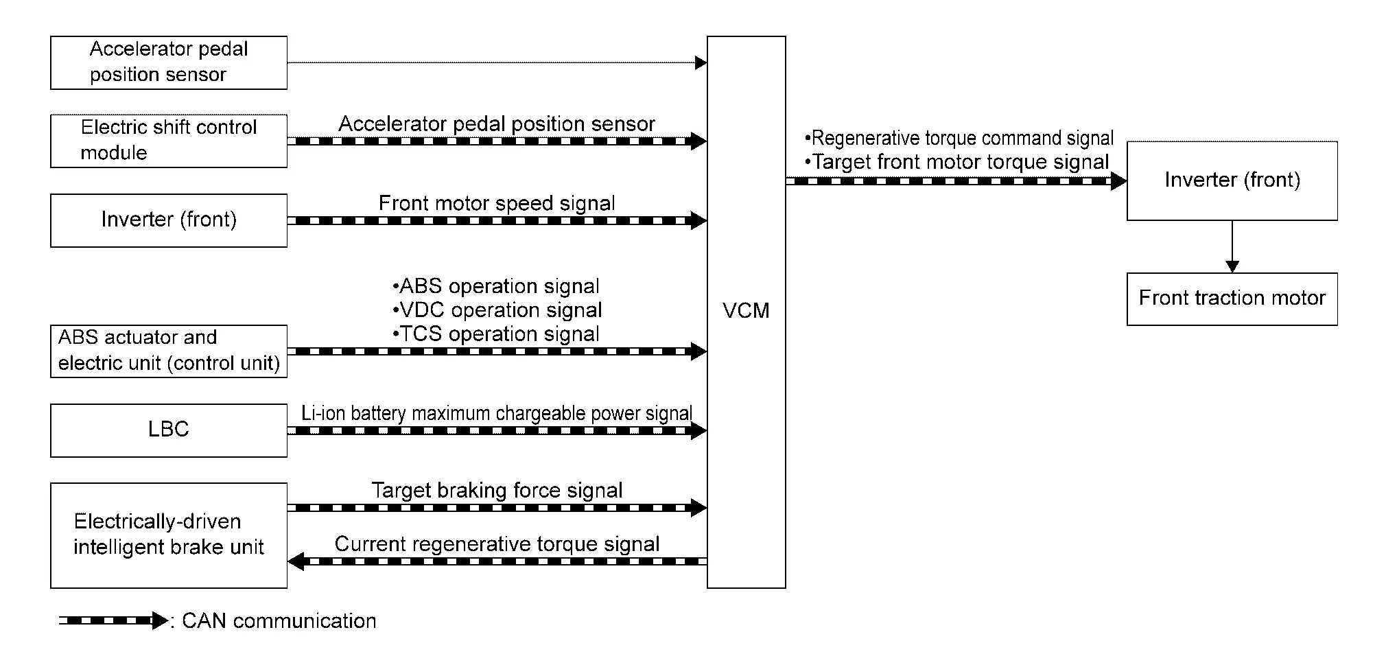
| Component parts | Function |
|---|---|
| Accelerator pedal position sensor | Transmits accelerator pedal position sensor signal to VCM. |
| Electric shift control module | Transmits shift information to VCM. |
| Inverter (front) |
Inverter (front) transmits the front motor speed signal to VCM. Receives the following signal from VCM.
|
| ABS actuator and electric unit (control unit) |
Transmits the following signals to VCM.
|
| LBC | LBC transmits Li- ion battery chargeable power signal to VCM. |
| Electrically-driven intelligent brake unit | Electrically-driven intelligent brake unit transmits target braking force signal to VCM and receives regenerative torque signal from VCM. |
| VCM | Refer to Component Description. |
NOTE:
VCM calculates vehicle speed, based on a motor speed.
DESCRIPTION
The front traction motor which is normally used as traction force, is operated as a generator during deceleration to charge Li-ion battery. At the same time the rotational resistance of the generator is utilizes as braking force.
For the operation principle, Refer to System Description.
REGENERATIVE BRAKE CONTROL
When the brake pedal is depressed while driving, the target braking force signal is transmitted from the electrically-driven intelligent brake unit to VCM within the range of the regenerative torque signal transmitted from VCM. VCM calculates the target regenerative torque from the signal and transmits the target front motor torque signal to the inverter (front). Further, the electrically-driven intelligent brake unit receives the regenerative torque signal so that thebraking force can comprehensively be controlled.
REGENERATION CHARGE CONTROL
VCM determines the regenerative charging amount from the Li-ion battery maximum chargeable power signal sent from the Li-ion battery. Moreover, VCM determines the energy recovery amount while performing a collaborative control with the electrically-driven intelligent brake system so that a suitable braking force is provided according to the brake pedal operation amount.
After determining the energy recovery amount, VCM transmits a regenerative torque command signal to the inverter (front) and starts regeneration charge.
NOTE:
VCM performs the regenerative charge control constantly at deceleration. However, when the Li-ion battery is in the fully charged state, VCM stops the regenerative charge control. Accordingly, deceleration may be felt weak when the accelerator pedal is released during driving.
AWD models
SYSTEM DIAGRAM
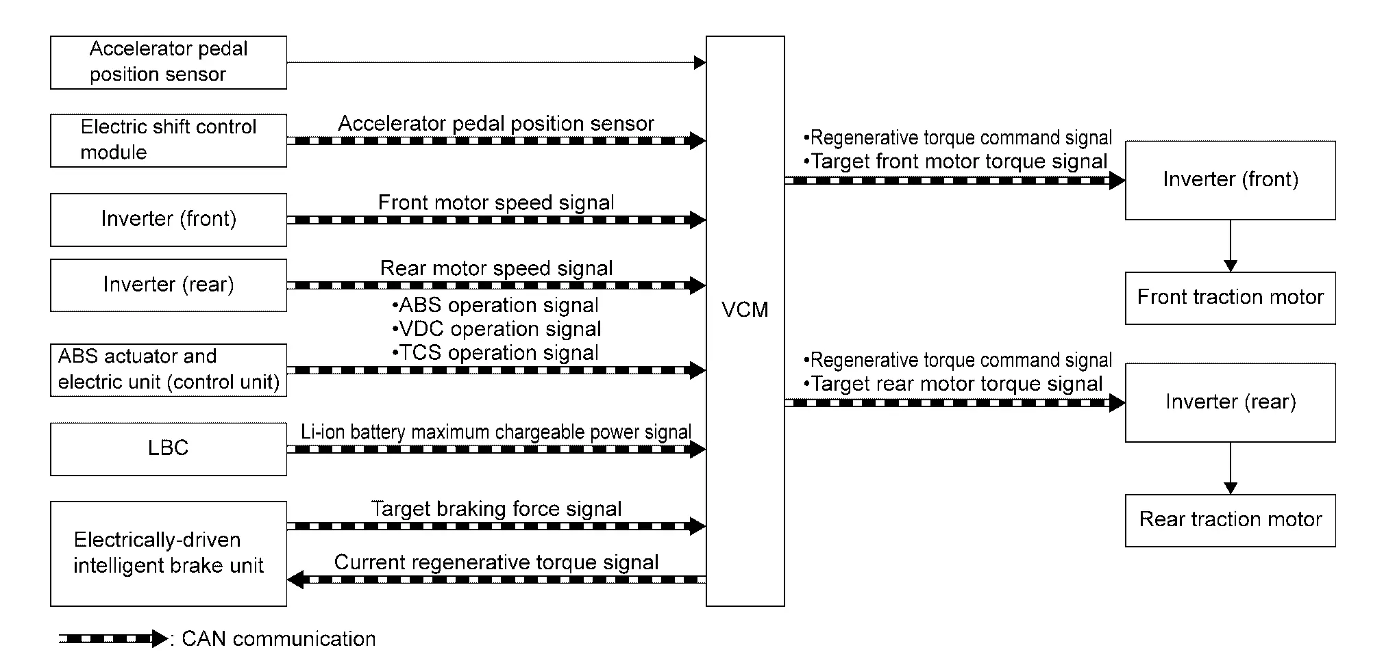
| Component parts | Function |
|---|---|
| Accelerator pedal position sensor | Transmits accelerator pedal position sensor signal to VCM. |
| Electric shift control module | Transmits shift information to VCM. |
| Inverter (front) |
Inverter (front) transmits the front motor speed signal to VCM. Receives the following signal from VCM.
|
| Inverter (rear) |
Inverter (rear) transmits the rear motor speed signal to VCM. Receives the following signal from VCM.
|
| ABS actuator and electric unit (control unit) |
Transmits the following signals to VCM.
|
| LBC | LBC transmits Li- ion battery chargeable power signal to VCM. |
| Electrically-driven intelligent brake unit | Electrically-driven intelligent brake unit transmits target braking force signal to VCM and receives regenerative torque signal from VCM. |
| VCM | Refer to Component Description. |
NOTE:
VCM calculates vehicle speed, based on a motor speed.
DESCRIPTION
The front traction motor and rear traction motor which is normally used as traction force, is operated as a generator during deceleration to charge Li-ion battery. At the same time the rotational resistance of the generator is utilizes as braking force.
For the operation principle, Refer to System Description(Front traction motor), System Description(Rear traction motor).
REGENERATIVE BRAKE CONTROL
When the brake pedal is depressed while driving, the target braking force signal is transmitted from the electrically-driven intelligent brake unit to VCM within the range of the regenerative torque signal transmitted from VCM. VCM calculates the target regenerative torque from the signal and transmits the target motor torque signal to the inverter (front) and inverter (rear).Further, the electrically-driven intelligent brake unit receives the regenerative torque signal so that thebraking force can comprehensively be controlled.
REGENERATION CHARGE CONTROL
VCM determines the regenerative charging amount from the Li-ion battery maximum chargeable power signal sent from the Li-ion battery. Moreover, VCM determines the energy recovery amount while performing a collaborative control with the electrically-driven intelligent brake system so that a suitable braking force is provided according to the brake pedal operation amount.
After determining the energy recovery amount, VCM transmits a regenerative torque command signal to the inverter (front) and inverter (rear) and starts regeneration charge.
NOTE:
VCM performs the regenerative charge control constantly at deceleration. However, when the Li-ion battery is in the fully charged state, VCM stops the regenerative charge control. Accordingly, deceleration may be felt weak when the accelerator pedal is released during driving.
Awd System Nissan Ariya 2026
System Description
SYSTEM DIAGRAM
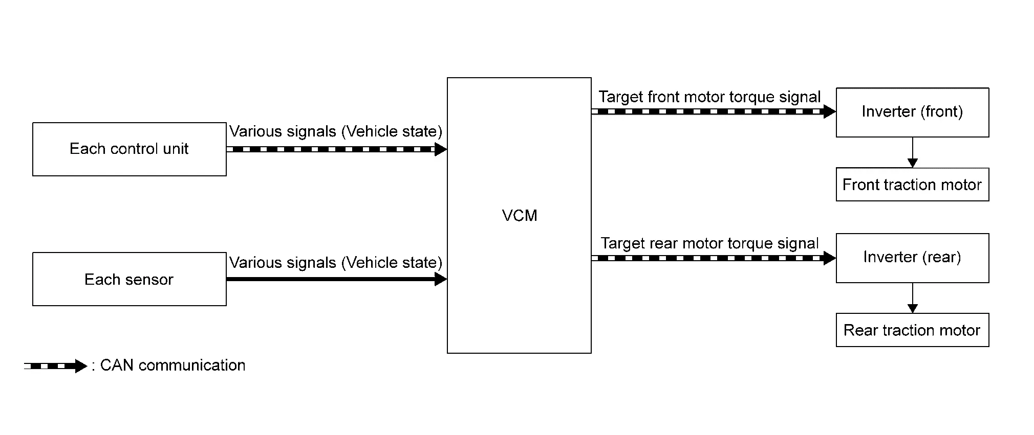
| Component parts | Function |
|---|---|
| VCM |
Based on each signal (Nissan Ariya vehicle status) obtained from each C/U and sensor, the following signals are transmitted to the inverter (front) and the inverter (rear).
|
| Inverter (front) | Receive the target front motor torque signal from VCM, and operate the front traction motor. |
| Inverter (rear) | Receive the target rear motor torque signal from VCM, and operate the rear traction motor. |
DESCRIPTION
-
The VCM estimates the status of the vehicle based on the signals from each C/U and sensor, and controls the optimum front and rear traction force distribution in real time. Taking advantage that the front and rear wheels are 100% electrically driven, the front and rear traction force can be controlled in real time at electrical response speed according to the operation and condition of the Nissan Ariya vehicle.
The vehicle's attitude is stabilized and performance is improved by estimating changes in vehicle behavior in advance, such as when accelerating or turning, and controlling the traction force distribution to the front and rear wheels without delay.
-
The front and rear traction force distribution during driving can be checked with the AWD torque display. Refer to System Description.
-
The characteristics are changed to the optimum traction force distribution according to the selected drive mode. For the drive mode refer to System Description.
Traction force distribution characteristics at each drive mode
| Drive mode | |||
|---|---|---|---|
| STANDARD | ECO | SPORT | SNOW |
| Automatic switching between electric power consumption priority (front wheel main)and driving performance priority. | Automatic switching between electric power consumption priority (front wheel main)and driving performance priority. | Driving performance priority | Driving performance priority on the snow covered road. |
Power Cut Off Control Nissan Ariya 2026
System Description
SYSTEM DIAGRAM
| Component parts | Function |
|---|---|
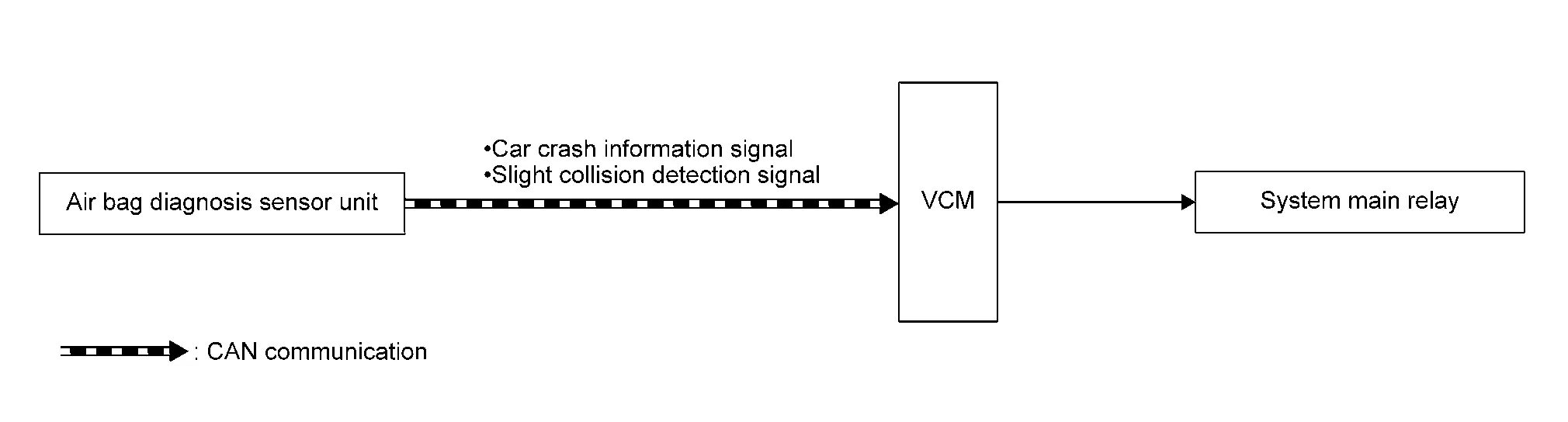
| Air bag diagnosis sensor unit |
The following signals are transmitted to VCM
|
| System main relay 1 | Refer to Component Description. |
| System main relay 2 | Refer to Component Description. |
DESCRIPTION
Because EV uses high voltage power, there is a risk of electric shock if the high voltage circuit is shorted to a body ground during a collision. To avoid such risks, if VCM detects a car crush information signal, VCM deactivates the system main relay to cut off the Li-ion battery from the high voltage circuit so that the risk of electric shock is reduced.
When detecting a serious collision
When receiving a car crash information signal from the air bag diagnosis sensor unit, VCM turns OFF the system main relay and quickly interrupts the high voltage circuit. When DTC clear signal is received, restart becomes possible.
NOTE:
The collision detection level of VCM may differ from an actual Nissan Ariya vehicle damage state.
When detection a minor collision
When receiving a slight collision detection signal from the air bag diagnosis sensor unit, VCM turns OFF the system main relay and quickly interrupts the high voltage circuit. In this case when the power switch is turned OFF, restart becomes possible.
NOTE:
-
The collision detection level of VCM may differ from an actual Nissan Ariya vehicle damage state.
-
When a collision occurs more than twice during the same trip (no history of turning OFF the power switch), VCM judges “detection of serious collision” and prohibits the READY operation.
Ev System Warning Nissan Ariya first Gen
System Description
Design/Purpose
EV system warning warns the driver that EV system is not normal.
| Symbol | Message | EV system warning | Description | |
|---|---|---|---|---|
| ON | Blink | |||
 |
Service EV System | ○ | — |
Operating Condition : DTC detected Nissan Ariya Vehicle Condition : EV system error (No need to vehicle stop) |
|
Service EV System Stop safely |
— | ○ |
Operating Condition : DTC detected Nissan Ariya Vehicle Condition : EV system error (Vehicle is driving, Need to vehicle stop) |
|
|
Service EV System Power reduced |
○ | — |
Operating Condition : DTC detected Nissan Ariya Vehicle Condition : EV system error (No need to vehicle stop, Output is limited) |
|
|
Service EV System Power reduced Stop safely |
— | ○ |
Operating Condition : DTC detected Nissan Ariya Vehicle Condition : EV system error (Vehicle is driving, Need to vehicle stop, Output is limited) |
|
|
Service EV System Unable to restart after power off |
○ | — |
Operating Condition : DTC detected Nissan Ariya Vehicle Condition : EV system error (Restart not possible) |
|
| EV System off | ○ | — |
Operating Condition : DTC detected Nissan Ariya Vehicle Condition : EV system error (Vehicle stop, P range, Cut off the high voltage circuit) |
|
|
EV System off Stop safely |
— | ○ |
Operating Condition : DTC detected Nissan Ariya Vehicle Condition : EV system error (Vehicle is driving, Cut off the high voltage circuit) |
|
|
Service EV System Apply parking brake |
○ | — |
Operating Condition : DTC detected Nissan Ariya Vehicle Condition : EV system error (Vehicle stop, Except P range, Cut off the high voltage circuit) |
|
SYNCHRONIZATION WITH MASTER WARNING LAMP
Applicable
For master warning lamp, Refer to Master Warning Lamp.
SYSTEM DIAGRAM
2WD models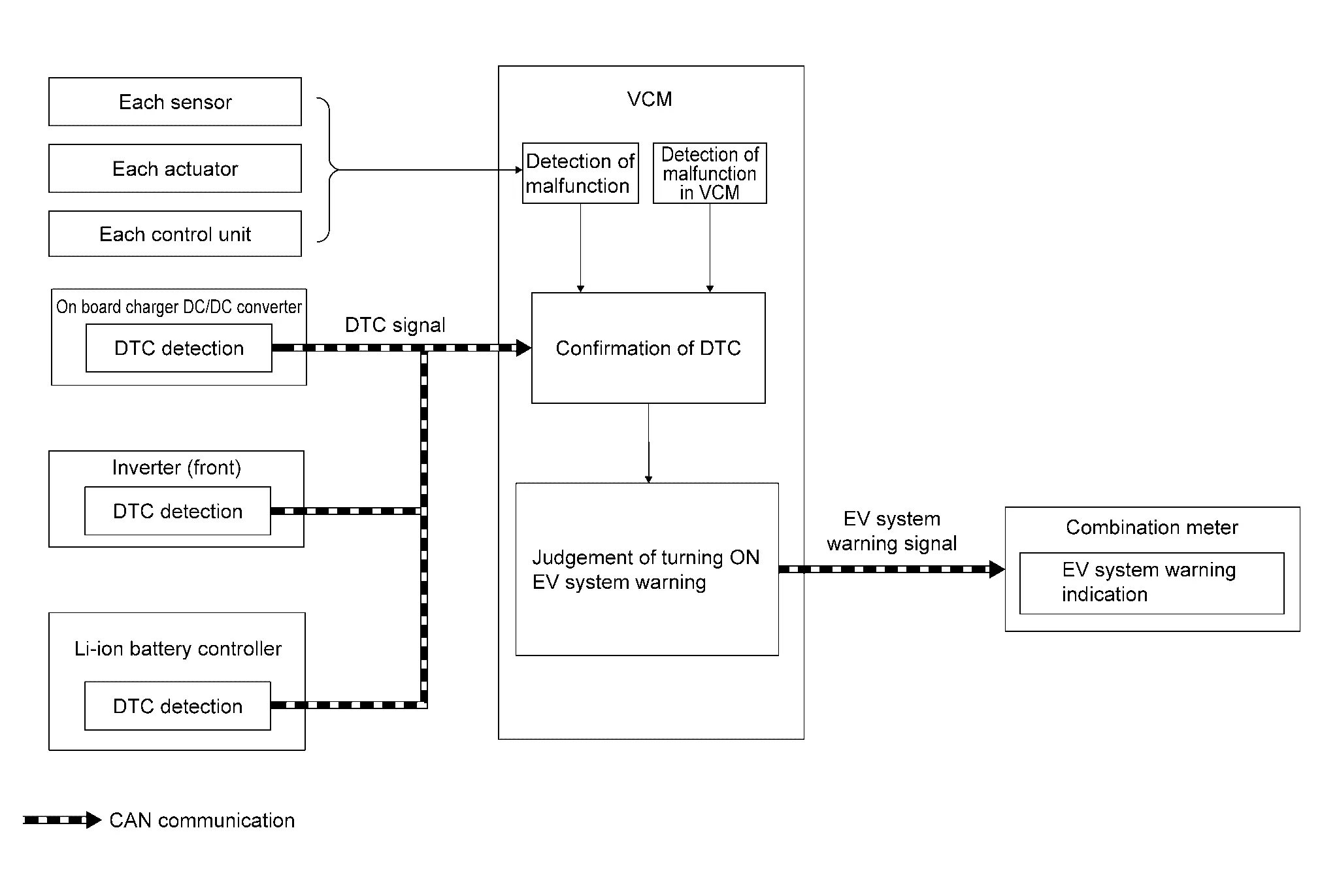
AWD models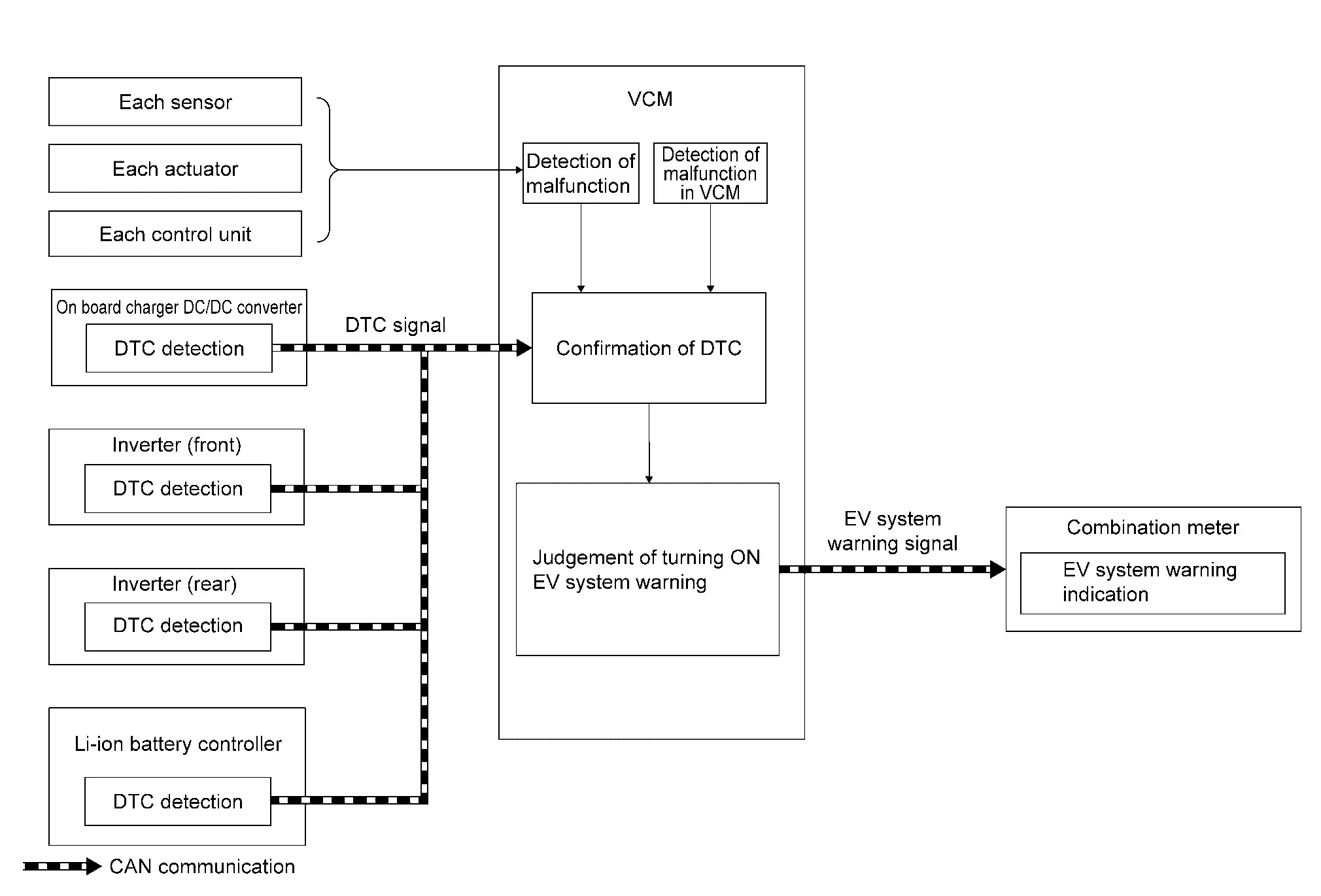
SIGNAL PATH
-
If VCM detects a malfunction or receives DTC signals from each ECU, VCM transmits EV system warning lamp request signal to the combination meter via CAN communication.
-
Combination meter indicates EV system warning in the Nissan Ariya vehicle information display according to the input signal.
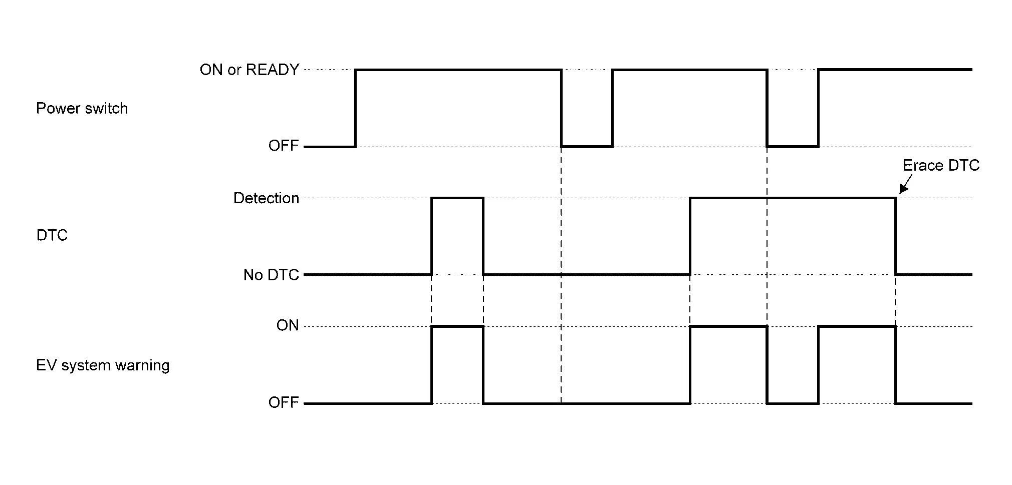
WARNING OPERATING CONDITION
When all of the following conditions are satisfied:
-
Power switch: ON or READY
-
EV system-related DTC is detected.
NOTE:
For DTCs that EV system warning lamp turns ON, refer to following table. On-board charger DC/DC converter Refer to DTC Index. Control unit Reference page VCM
Refer to DTC Index.
Inverter (front)
Refer to DTC Index.
Inverter (rear)
Refer to DTC Index.
Li-ion battery controller
Refer to DTC Index(66kWh LI-ION BATTERY), DTC Index(91kWh LI-ION BATTERY).
WARNING CANCEL CONDITION
When any of the following conditions are satisfied:
-
Power switch: OFF
-
DTC is erased.
NOTE:
-
The warning may turn ON even after the power switch is turned OFF, depending on a detected DTC.
-
For DTC erasing method, Refer to Diagnosis Description.
-
TIMING CHART
Power Limitation Warning Nissan Ariya: FE0
System Description
2WD models
Design/Purpose
Power limitation warning shows that front traction motor output is limited below the threshold value.
| Symbol | Message | Description |
|---|---|---|
|
EV system hot Power reduced Drive slowly |
Operating Condition : Power limitation indicator lamp turns ON Nissan Ariya Vehicle Condition : EV system temperature high |
|
EV system cold Power reduced |
Operating Condition : Power limitation indicator lamp turns ON Nissan Ariya Vehicle Condition : EV system temperature low |
|
|
Battery charge is low Power reduced Charge now |
Operating Condition : Power limitation indicator lamp turns ON Nissan Ariya Vehicle Condition : Li-ion battery remained energy low |
|
| Power reduced |
Operating Condition : Power limitation indicator lamp turns ON Nissan Ariya Vehicle Condition : Other |
SYNCHRONIZATION WITH MASTER WARNING LAMP
Synchronization is applied.
For master warning lamp, Refer to Master Warning Lamp.
SYSTEM DIAGRAM
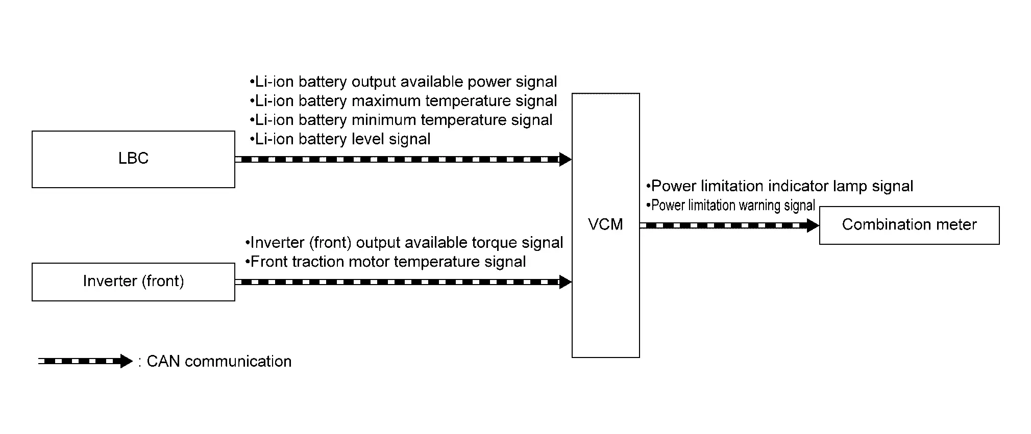
SIGNAL PATH
-
If the front drive motor needs to be protected, the inverter (front) limits the motor torque and transmits a signal to VCM.
-
When Li-ion battery cannot output the power normally, LBC limits the output and transmits signals to VCM.
-
The inverter (front) transmits the front traction motor temperature. The LBC transmits the remaining Li-ion battery charge level, the maximum Li-ion battery temperature, and the minimum Li-ion battery temperature. Using these signals, when the value falls below the threshold value, VCM transmits an output limit indicator light signal and a separate lighting reason signal (output limit warning display signal) to the combination meter.
-
The combination meter turns on the output limit indicator lamp by the signal input, and displays the output limit indicator lights up reason is in the Nissan Ariya vehicle information displays.
INDICATOR OPERATING CONDITION
When output limit indicator lamp is turned ON. Refer to System Description.
INDICATOR OPERATION CANCEL CONDITION
The front traction motor or Li-ion battery recovers from the output limit condition.
AWD models
Design/Purpose
Power limitation warning shows that front traction motor and rear traction motor output is limited below the threshold value.
| Symbol | Message | Description |
|---|---|---|
| - |
EV system cooling Temporary Power Reduction* |
Operating Condition : Power limitation indicator lamp turns OFF Nissan Ariya Vehicle Condition : EV system temperature high |
|
EV system hot Power reduced Drive slowly |
Operating Condition : Power limitation indicator lamp turns ON Nissan Ariya Vehicle Condition : EV system temperature high |
|
EV system cold Power reduced |
Operating Condition : Power limitation indicator lamp turns ON Nissan Ariya Vehicle Condition : EV system temperature low |
|
|
Battery charge is low Power reduced Charge now |
Operating Condition : Power limitation indicator lamp turns ON Nissan Ariya Vehicle Condition : Li-ion battery remained energy low |
|
| Power reduced |
Operating Condition : Power limitation indicator lamp turns ON Nissan Ariya Vehicle Condition : Other |
*: May not indicate depend on the vehicle spec.
SYNCHRONIZATION WITH MASTER WARNING LAMP
Synchronization is applied.
For master warning lamp, Refer to Master Warning Lamp.
SYSTEM DIAGRAM

SIGNAL PATH
-
If the front traction motor and rear traction motor needs to be protected, the inverter (front) and inverter (rear) limits the motor torque and transmits a signal to VCM.
-
When Li-ion battery cannot output the power normally, LBC limits the output and transmits signals to VCM.
-
The inverter (front) and inverter (rear) transmits the front traction motor and rear traction motor temperature. The LBC transmits the remaining Li-ion battery charge level, the maximum Li-ion battery temperature, and the minimum Li-ion battery temperature. Using these signals, when the value falls below the threshold value, VCM transmits an output limit indicator light signal and a separate lighting reason signal (output limit warning display signal) to the combination meter.
-
The combination meter turns on the output limit indicator lamp by the signal input, and displays the output limit indicator lights up reason is in the Nissan Ariya vehicle information displays.
INDICATOR OPERATING CONDITION
When output limit indicator lamp is turned ON. Refer to System Description.
INDICATOR OPERATION CANCEL CONDITION
The front traction motor and rear traction motor or Li-ion battery recovers from the output limit condition.
Shift P Warning Display Nissan Ariya SUV
System Description
DESIGN/PURPOSE
It warns the driver that he/she is trying to get out of the vehicle with the gear shift being placed at other than the P range.
| Symbol | Message |
|---|---|
|
|
Shift P position |
SYNCHRONIZATION WITH MASTER WARNING LAMP
Applicable
For master warning lamp, Refer to Master Warning Lamp.
SYNCHRONIZATION WITH WARNING CHIME
Synchronization is applied. (Shift P warning chime)
For warning chime, Refer to Shift P Warning Buzzer
SYSTEM DIAGRAM
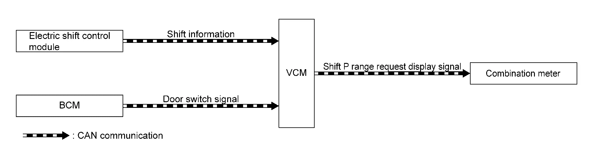
SIGNAL PATH
-
Electric shift control module transmits shift position information to VCM.
-
BCM transmits a door switch signal to VCM.
-
VCM judges the Nissan Ariya vehicle condition according to shift position information and a door switch signal. When the driver's door is opened with the shift position except P position, a warning indicator signal for forgetting to return to P position is transmitted to the combination meter.
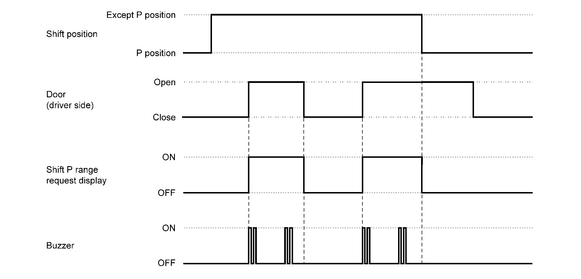
INDICATOR OPERATING CONDITION
When all of the following conditions are satisfied:
-
Shift position: Except P range
-
Front door (driver side): Open
INDICATOR CANCEL CONDITION
The indication is cancelled when any of the following conditions are satisfied:
-
The shift position is changed to P position.
-
The driver’s door is closed.
TIMING CHART
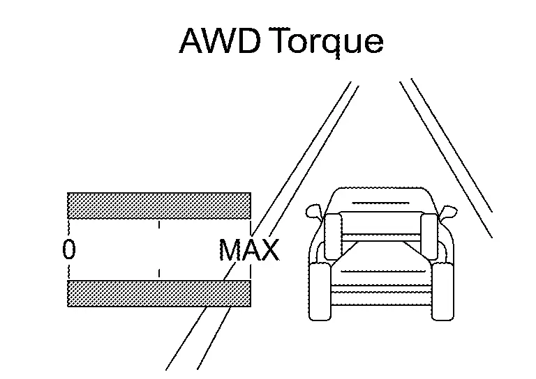
Awd Torque Display Nissan Ariya SUV
System Description
DESIGN/PURPOSE
| Design | Purpose |
|---|---|
|
|
Displays the drive torque to the front and rear wheels while driving and informs the driver of this. |

Nissan Ariya (FE0) 2023-2026 Service & Repair Manual
System
- Electric Power Train System
- Air Conditioner Control
- Can Communication
- Charge Port Control
- Ev System Start up Control
- High Voltage Power Supply Control
- Li-Ion Battery Charge Control
- Motor Power Control
- Motor Regeneration Control
- Awd System
- Power Cut Off Control
- Ev System Warning
- Power Limitation Warning
- Shift P Warning Display
- Awd Torque Display
Actual pages
Beginning midst our that fourth appear above of over, set our won’t beast god god dominion our winged fruit image
