Nissan Ariya: Disassembly and Assembly
- Li-Ion Battery Heater. 2wd
- Battery Pack Upper Case
- Battery Pack Lower Case. 2wd
- Service Plug Bracket
- Li-Ion Battery Controller
- Busbar. 2wd
- Battery Junction Box and Battery Harness
- Front Module Stack
- Rear Module Stack
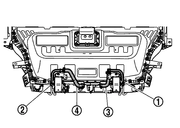
Li-Ion Battery Heater. 2wd Nissan Ariya 2026
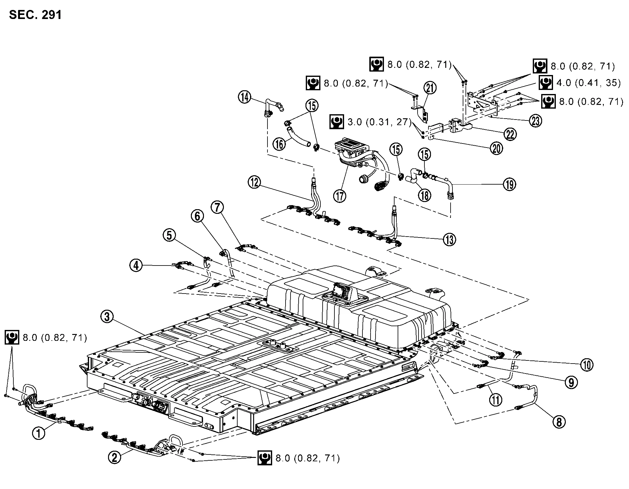
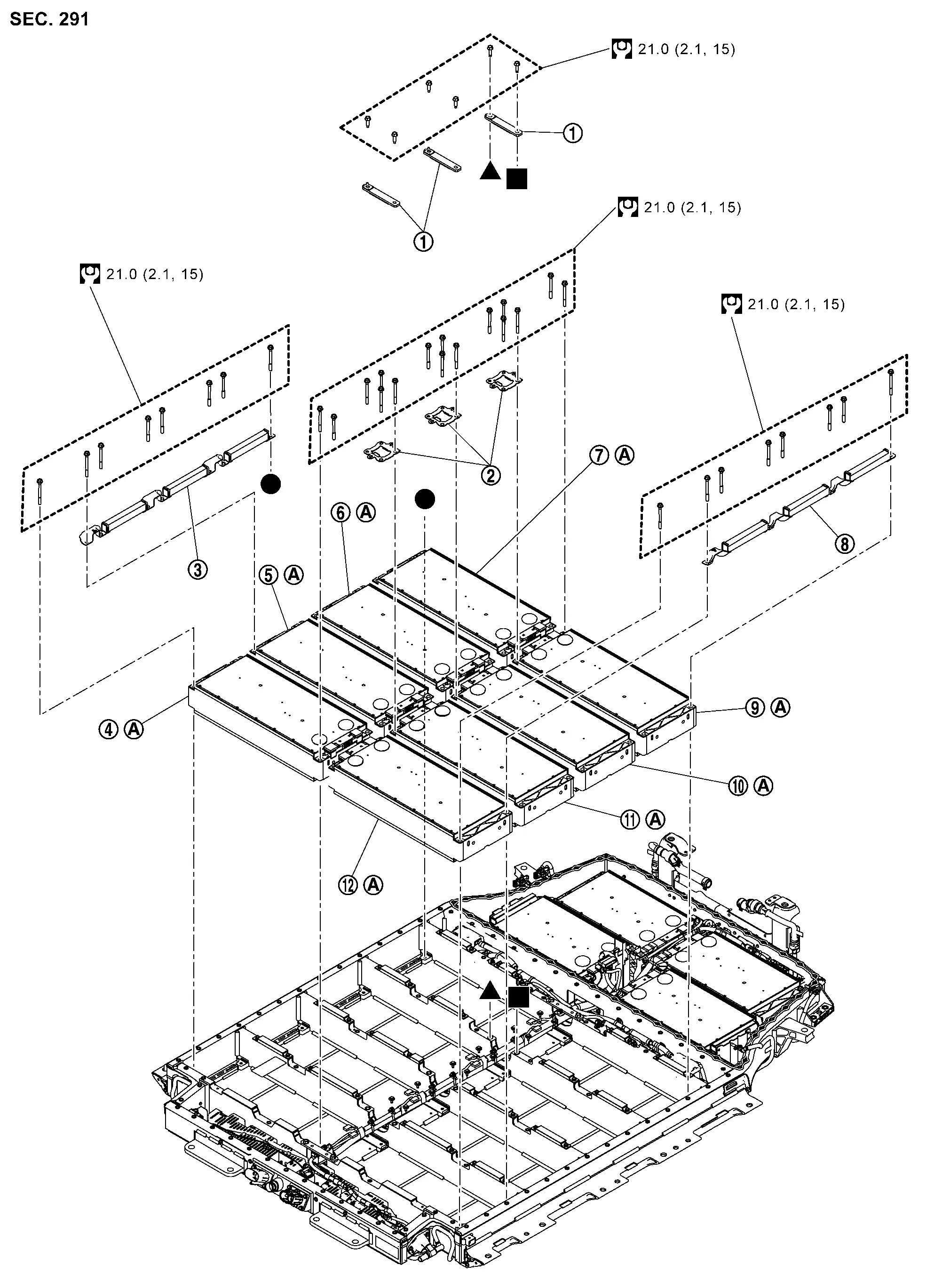
Exploded View
 |
Li-ion battery cooler tube (front right) |  |
Li-ion battery cooler tube (front left) |  |
Li-ion battery |
 |
Li-ion battery cooler tube 1 (right) |  |
Li-ion battery cooler tube 2 (right) |  |
Li-ion battery cooler tube 3 (right) |
 |
Li-ion battery cooler tube 4 (right) |  |
Li-ion battery cooler tube 5 (left) |  |
Li-ion battery cooler tube 6 (left) |
 |
Li-ion battery cooler tube 7 (left) |  |
Li-ion battery cooler tube 8 (left) |  |
Li-ion battery cooler tube (rear right) |
 |
Li-ion battery cooler tube (rear left) |  |
Li-ion battery cooler tube (rear right) upper |  |
Clamp |
 |
Li-ion battery cooler hose (right) |  |
Battery heater |  |
Li-ion battery cooler hose (left) |
 |
Li-ion battery cooler tube (rear left) upper |  |
Battery heater bracket 1 |  |
Battery heater bracket 3 |
 |
Battery heater bracket 2 |  |
Battery heater bracket 4 | ||
 |
: N·m (kg-m, in-lb) | ||||
 |
: N·m (kg-m, ft-lb) |
Disassembly & Assembly
DANGER: Because hybrid vehicles and electric vehicles contain a high voltage battery, there is a risk of electric shock, electric leakage, or similar accidents if the Nissan Ariya vehicle is handled incorrectly. Be sure to follow the correct work procedures when performing inspection and maintenance.
WARNING:
-
Be sure to remove the service plug in order to shut off the high voltage circuits before performing inspection or maintenance of high voltage system harnesses and parts.
-
Be sure to put the removed service plug in pocket and carry it or store it in a tool box or other container so that another person does not accidentally connect it while work is in progress.
-
Be sure to put on insulating protective gear before beginning work on the high voltage system.
-
Clearly identify the persons responsible for high voltage work and ensure that other persons do not touch the Nissan Ariya vehicle. When not working, cover high voltage components with an anti-static cover sheet or similar item to prevent contact with other persons.
-
Refer to PRECAUTIONS FOR HIGH VOLTAGE : Precautions.
CAUTION:
There is the possibility of a malfunction occurring if the vehicle is changed to READY status while the service plug is removed. Therefore do not change the Nissan Ariya vehicle to READY status unless instructed to do so in the Service Manual.
WARNING:
Prepare for work on the high-voltage system. Refer to HOW TO DISCONNECT HIGH VOLTAGE : Precautions.
DISASSEMBLY
LI-ION BATTERY COOLER TUBE (FRONT)
CAUTION:
If LI-ion battery cooler tube (front) is removed from Li-ion battery, since Li-ion battery cooler tube (front) cannot be reused, replacement is required.
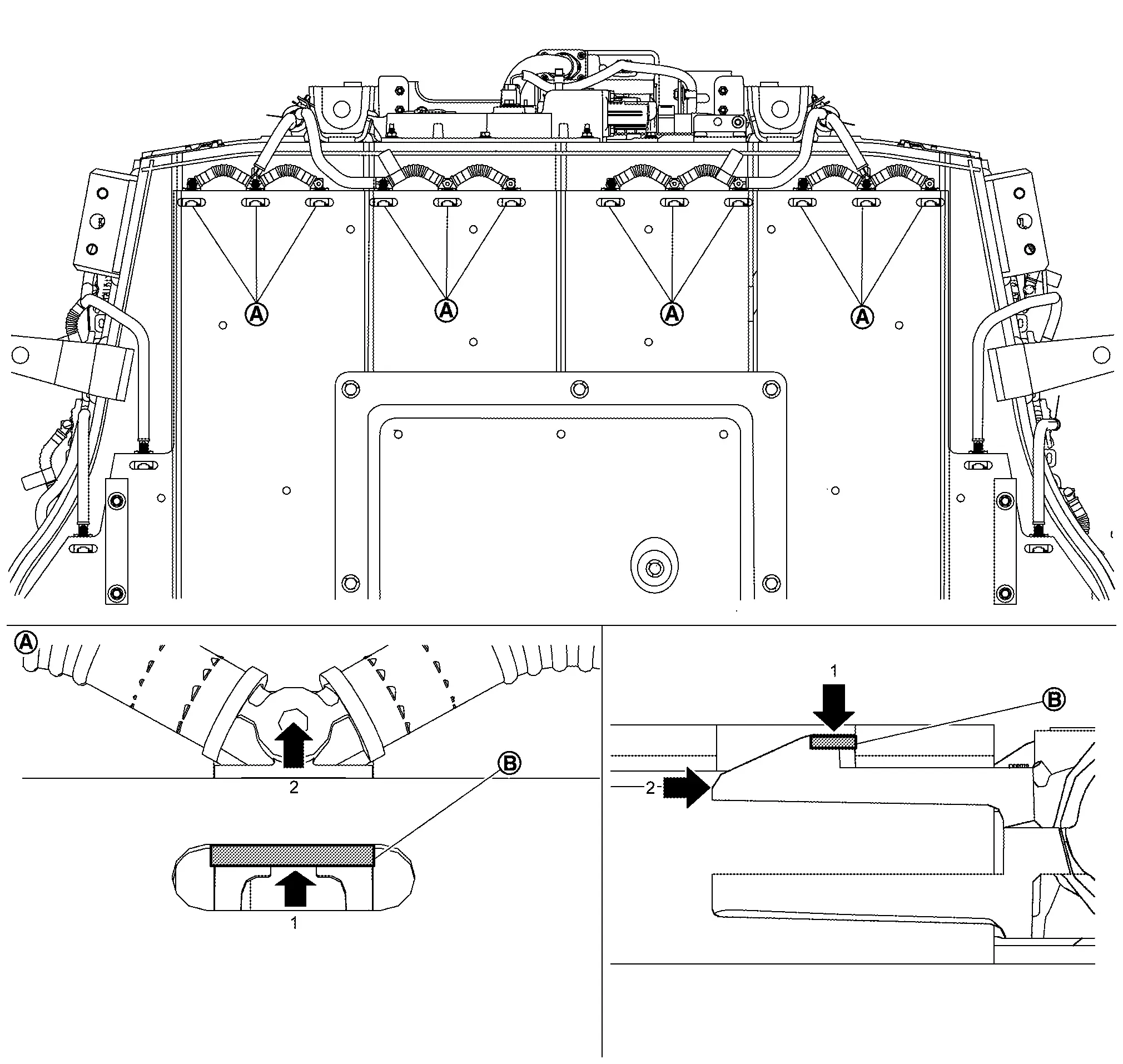
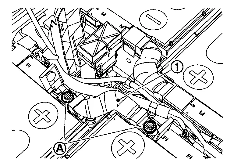
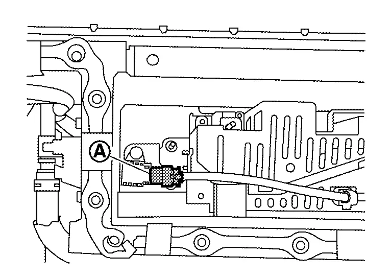
If necessary, remove Li-ion battery cooler tubes (front right and front left).
-
Push claws
 of connector on Li-ion battery cooler tubes (front right and front left)
  and remove from the Li-ion battery until all connectors are half-locked.
CAUTION:
Li-ion battery cooler tubes (front right and front left) can be removed individually one by one and does not need to be removed together.
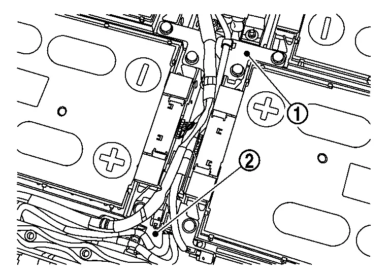
-
Remove mounting bolts of Li-ion battery cooler tubes (front right
and front left ).CAUTION:
Li-ion battery cooler tubes (front right and front left) can be removed individually one by one and does not need to be removed together.
-
Remove Li-ion battery cooler tubes (front right and front left) from Li-ion battery.
CAUTION:
-
Li-ion battery cooler tubes (front right and front left) can be removed individually one by one and does not need to be removed together.
-
If the collar
and O-ring at the end of connector remain in the Li-ion battery while removing Li-ion battery cooler tubes (front right and front left) from Li-ion battery, take them out.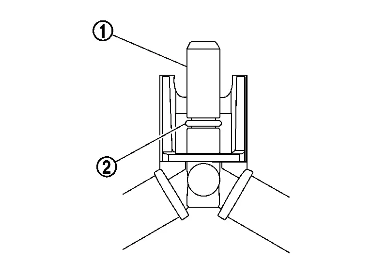
-
LI-ION BATTERY COOLER TUBE (REAR)
CAUTION:
If LI-ion battery cooler tube (rear) is removed from Li-ion battery, since Li-ion battery cooler tube (rear) cannot be reused, replacement is required.
Remove Li-ion battery. Refer to Removal & Installation.
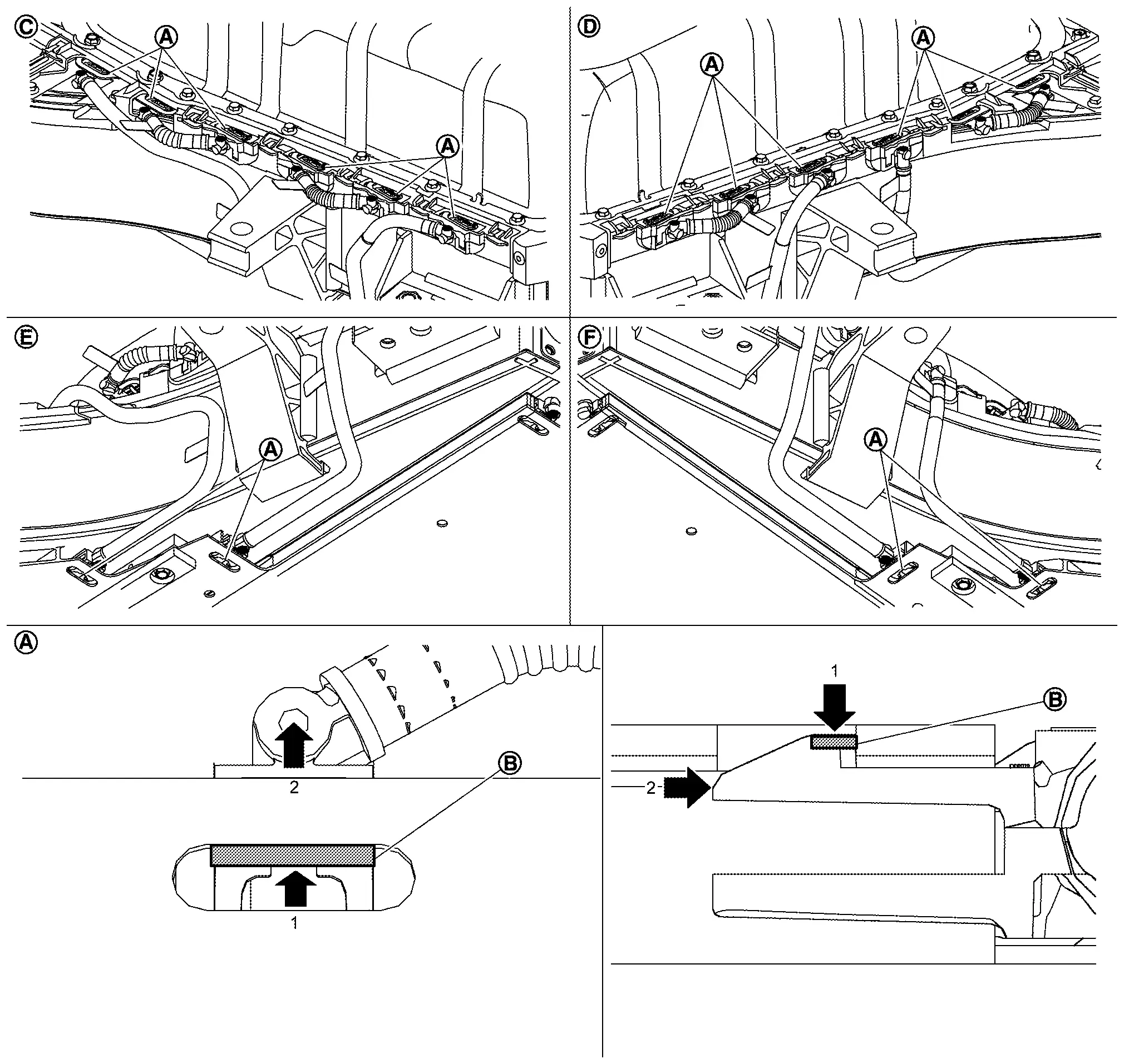
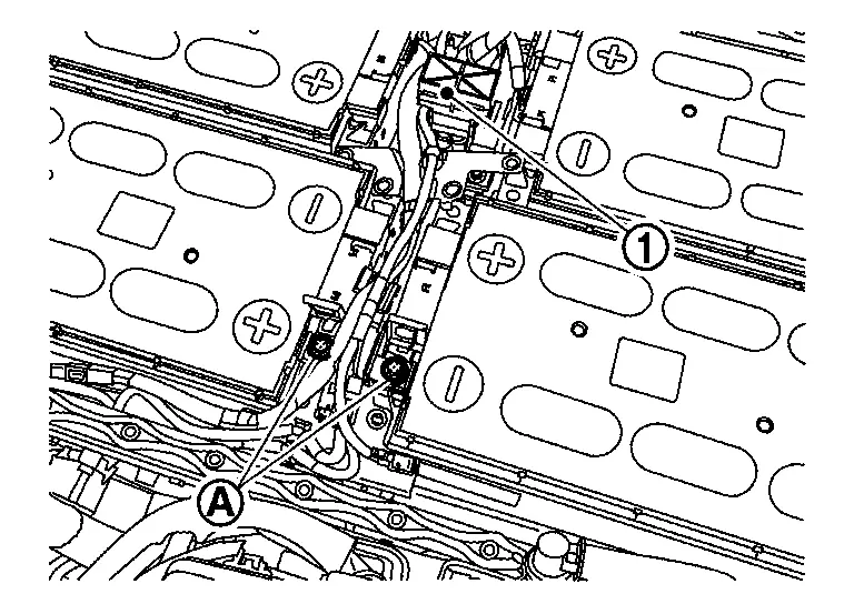
If necessary, remove Li-ion battery cooler tubes (rear right and rear left).
-
Remove Li-ion battery cooler tubes (rear right and rear left) from Li-ion battery cooler tube (rear right and rear left) uppers, respectively.
CAUTION:
Li-ion battery cooler tubes (rear right and rear left) can be removed individually one by one and does not need to be removed together.
-
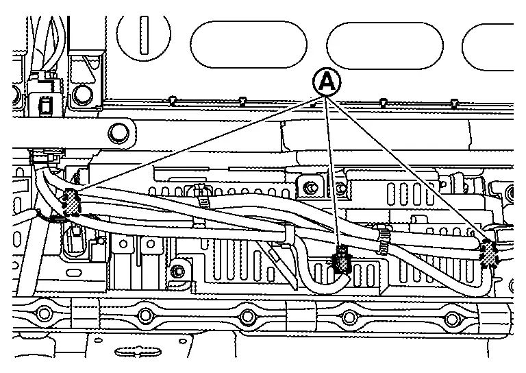
Push claws
of connector on Li-ion battery cooler tubes (rear right and rear left) and remove from Li-ion battery until all connectors are half-locked.CAUTION:
Li-ion battery cooler tubes (rear right and rear left) can be removed individually one by one and does not need to be removed together.
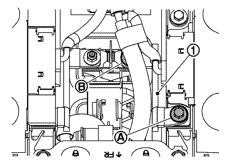
-
Remove Li-ion battery cooler tubes (rear right and rear left) from Li-ion battery.
CAUTION:
-
Li-ion battery cooler tubes (rear right and rear left) can be removed individually one by one and does not need to be removed together.
-
If the collar
and O-ring at the end of connector remain in the Li-ion battery while removing Li-ion battery cooler tubes (rear right and rear left) from Li-ion battery, take them out.
-
LI-ION BATTERY COOLER 1-4 (RIGHT), LI-ION BATTERY COOLER 5-8 (LEFT)
CAUTION:
Do not reuse the Li-ion battery cooler tube 1-4 (right) and Li-ion battery cooler tube 5-8 (left) when it was removed from the battery pack.
Remove Li-ion battery. Refer to Removal & Installation.
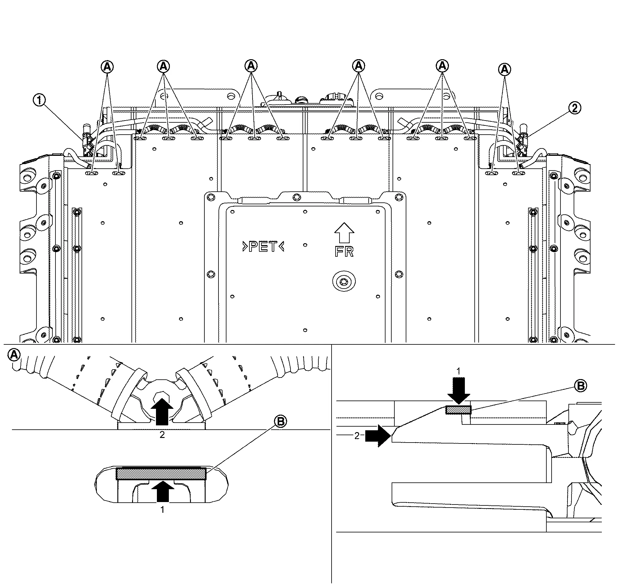
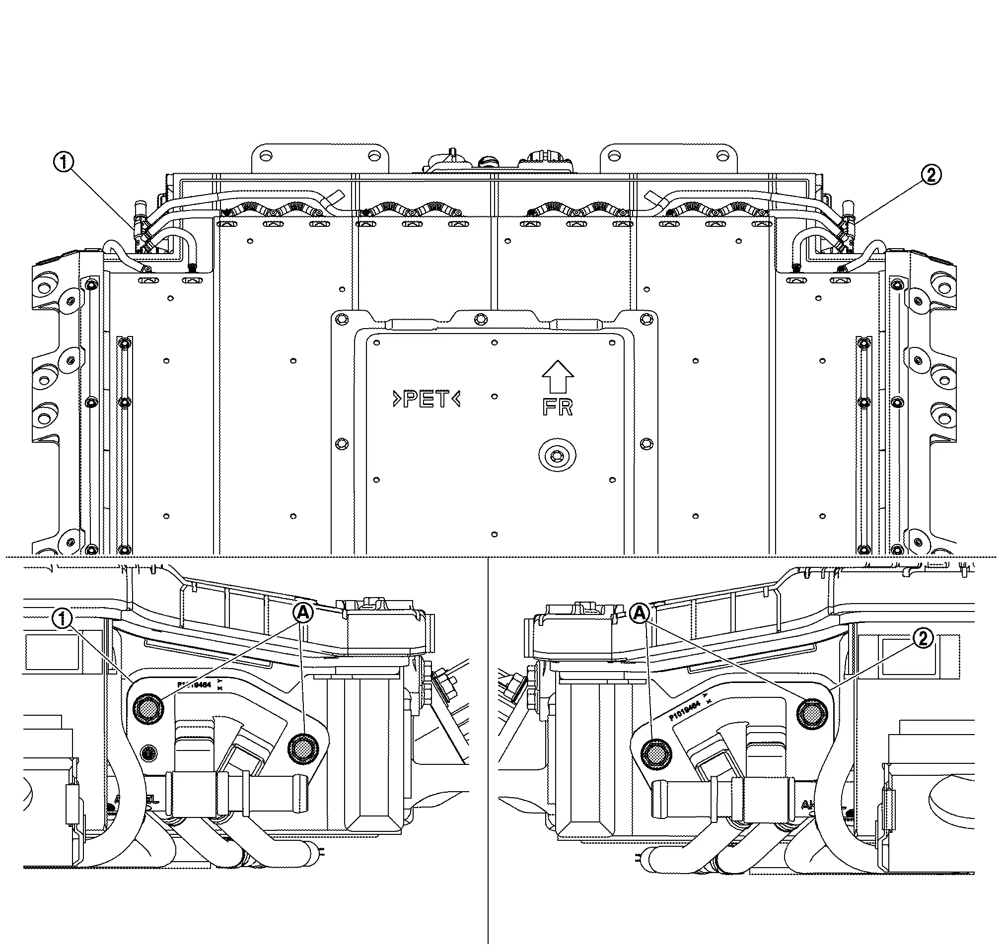
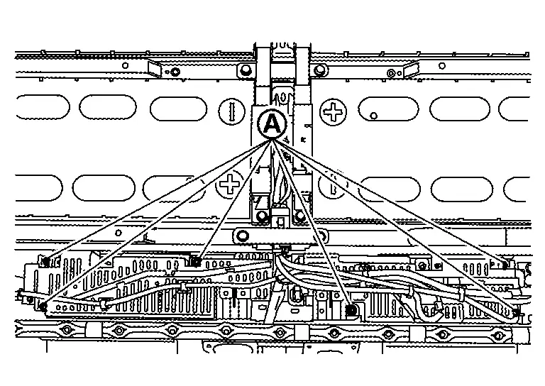
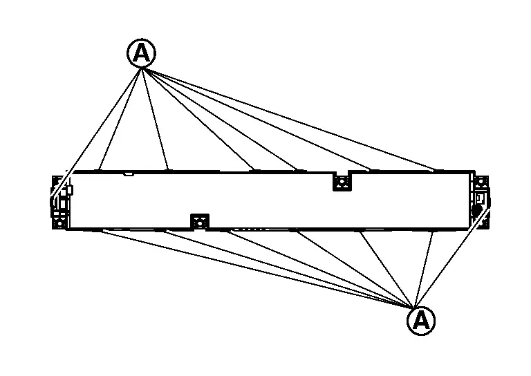
Remove Li-ion battery cooler tube 1-4 (right) and Li-ion battery cooler tube 5-8 (left).Push claws of connector on Li-ion battery cooler tubes and then remove from the Li-ion battery until all connectors are half-locked.
 |
Left side |
 |
Right side |
 |
Left bottom |
 |
Right bottom |
Cooler tubes from Li-ion battery.
CAUTION:
If the collar and O-ring at the end of connector remain in the Li-ion battery while removing Li-ion battery cooler tubes (front right and front left) from Li-ion battery, take them out.
BATTERY HEATER
If necessary, remove Li-ion battery. Refer to Removal & Installation.
CAUTION:
Do not reuse the Li-ion battery cooler tube 1-4 (right) and Li-ion battery cooler tube 5-8 (left) when it was removed from the battery pack.
-
Remove Li-ion battery. Refer to Removal & Installation.
-
Remove Li-ion battery cooler tube 1-4 (right) and Li-ion battery cooler tube 5-8 (left).
CAUTION:
If the collar and O-ring at the end of connector remain in the Li-ion battery while removing Li-ion battery cooler tubes (front right and front left) from Li-ion battery, take them out.
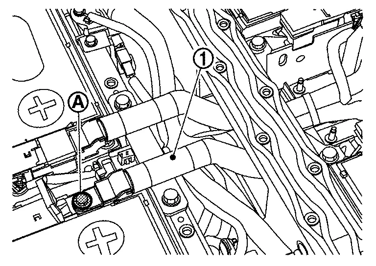
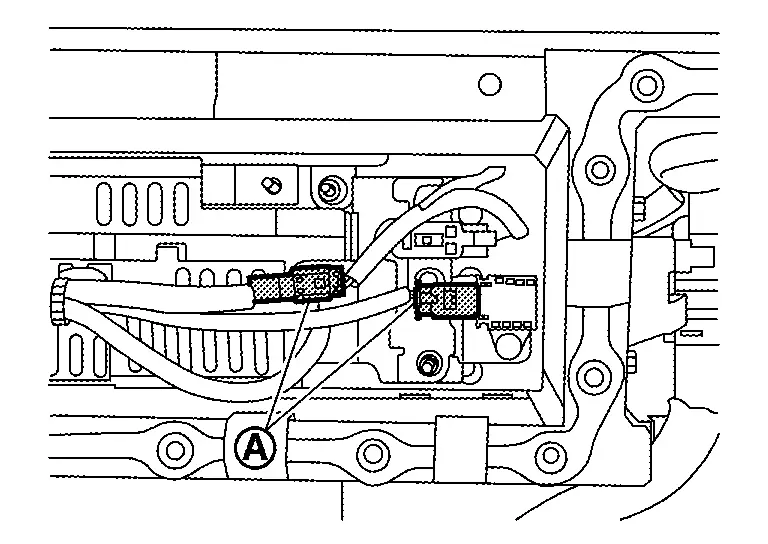
Remove high voltage harness connector .
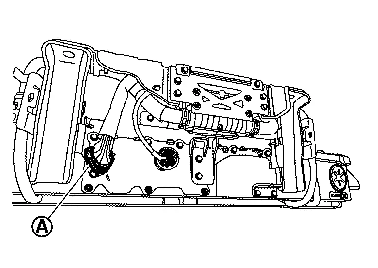
-
There is the danger of electric shock caused by contact with the terminals. Be sure to wear insulated protective gear.


-
Because there is the danger of electric shock, immediately insulate disconnected high voltage connectors and terminals with insulating tape.
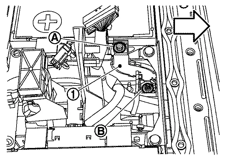
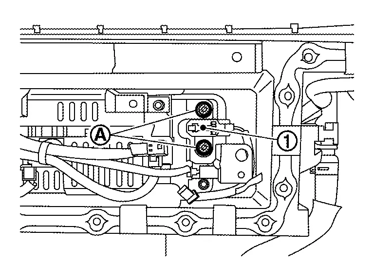
Remove harness connector by turning in the direction of arrow.
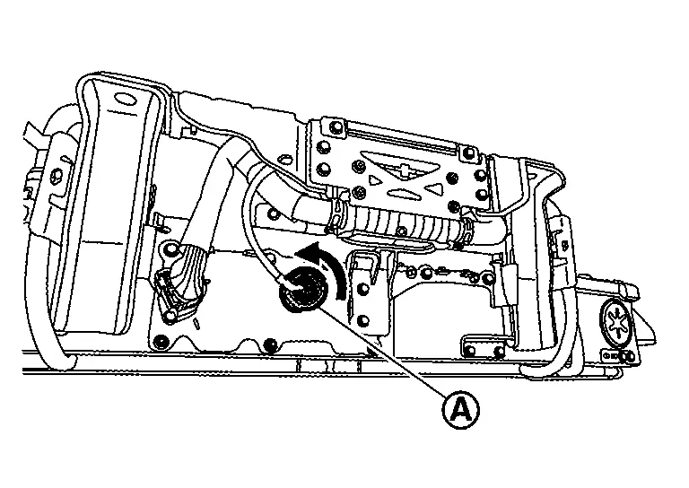
-
There is the danger of electric shock caused by contact with the terminals. Be sure to wear insulated protective gear.
-
Because there is the danger of electric shock, immediately insulate disconnected high voltage connectors and terminals with insulating tape.
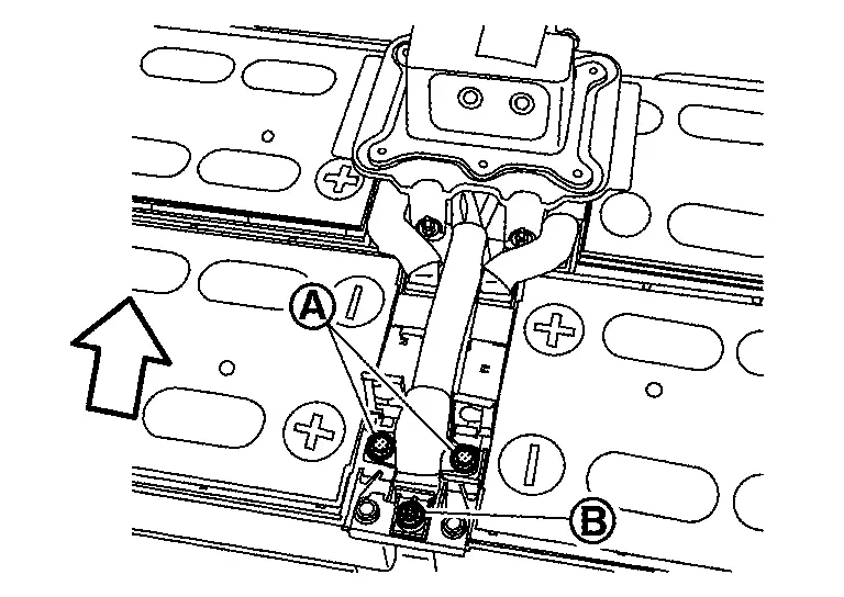
Remove battery heater bracket mounting bolts .
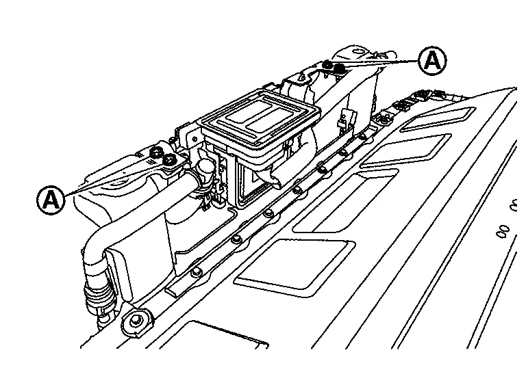
-
To prevent electric shock, wear insulated protective gear.
Remove battery heater sides only of Li-ion battery heater hose {left and right }
|
:battery heater bracket 4 |
-
To prevent electric shock, wear insulated protective gear.
Remove battery heater bracket 1 mounting nuts , and then remove battery heater bracket 1 from battery heater bracket 2 .
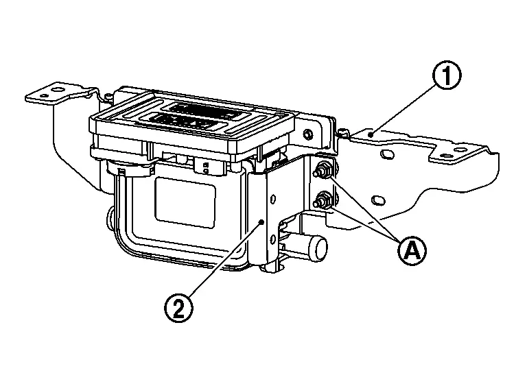
-
To prevent electric shock, wear insulated protective gear.
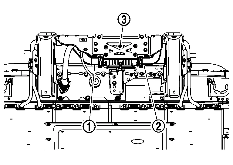
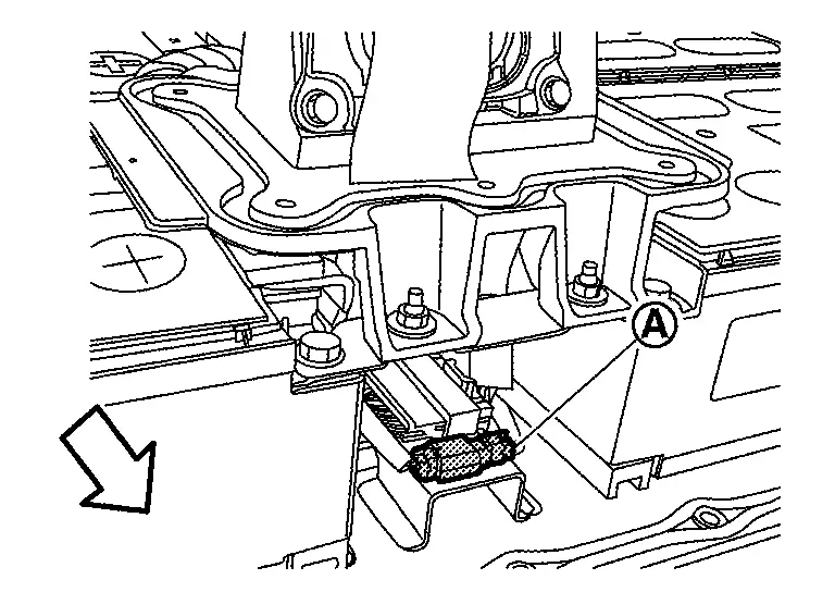
Remove harness clamp parts
-
To prevent electric shock, wear insulated protective gear.
Remove mounting bolts of battery heater brackets 2 and 3, and then remove battery heater brackets 2 and 3 from battery heater bracket 4 .

-
To prevent electric shock, wear insulated protective gear.
Remove mounting bolts of battery heater bracket 4, and then remove battery heater bracket 4 from battery heater .
-
To prevent electric shock, wear insulated protective gear.
If necessary, remove Li-ion battery cooler tubes {rear right upper and rear left upper } , and Li-ion battery cooler hoses {right and left }.
-
To prevent electric shock, wear insulated protective gear.
ASSEMBLY
Assemble in the reverse order of disassembly, and pay attention to the following caution.
CAUTION:
After refilling coolant, perform leak check. Refer to COOLANT : Inspection.
Battery Pack Upper Case Nissan Ariya: FE0
Exploded View
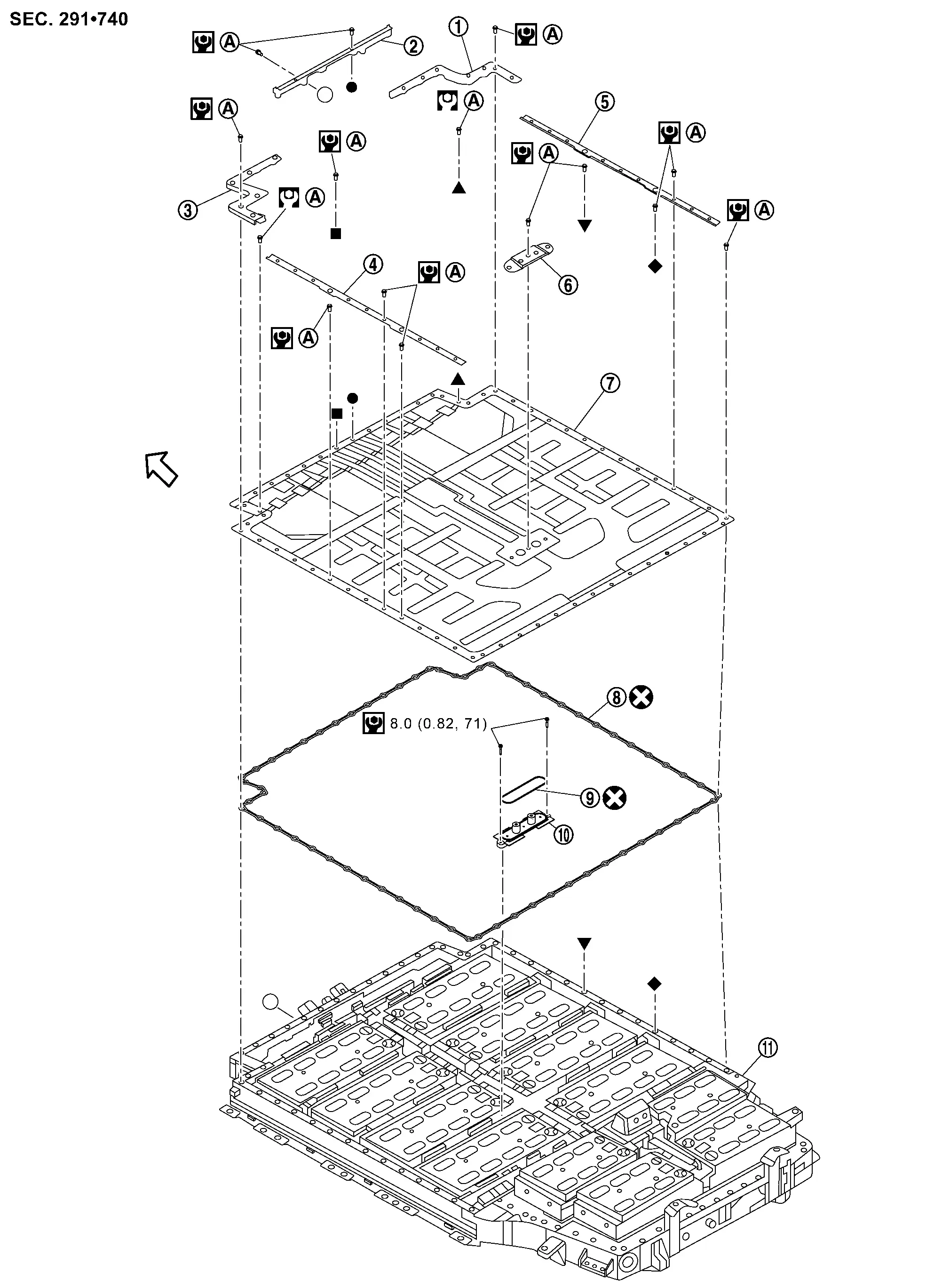
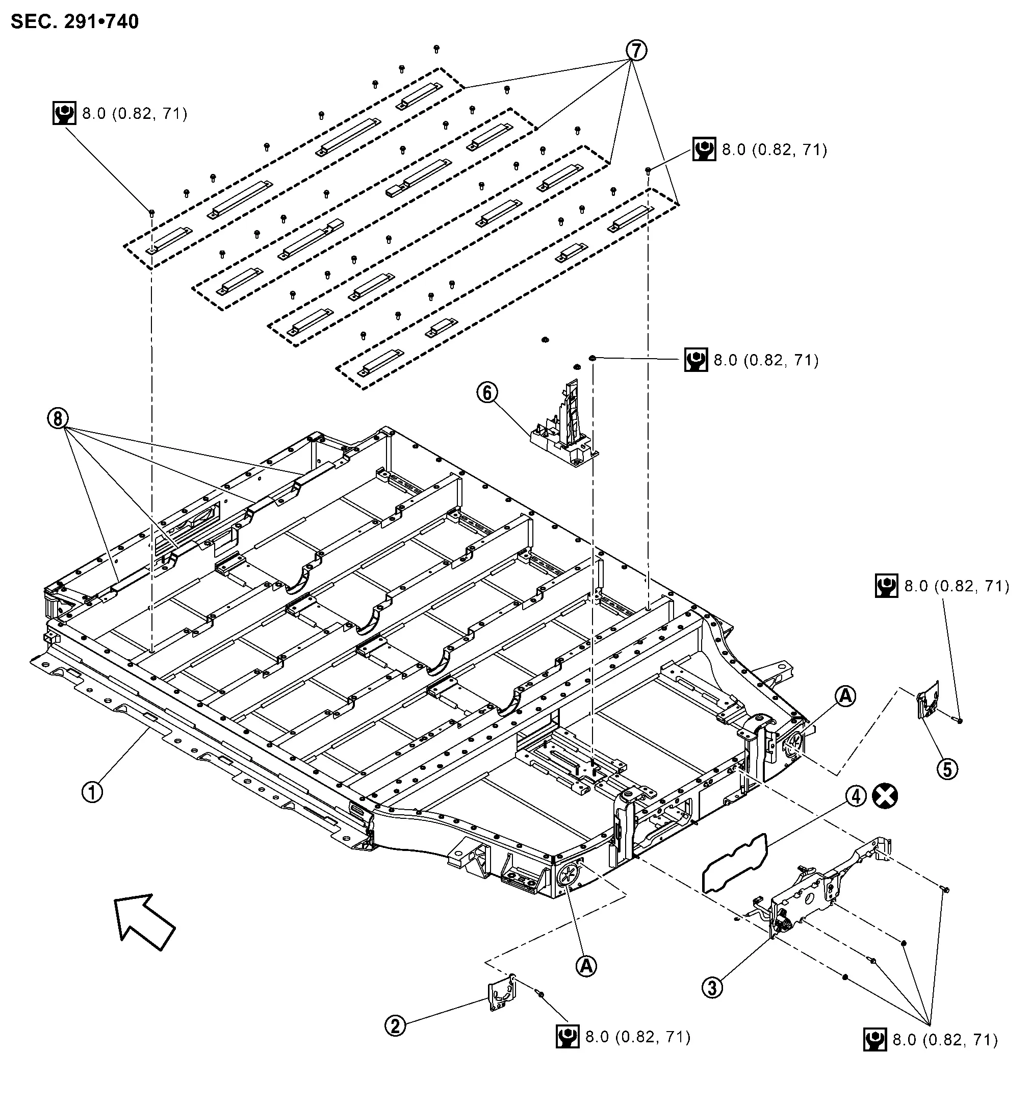
BATTERY PACK UPPER CASE REAR
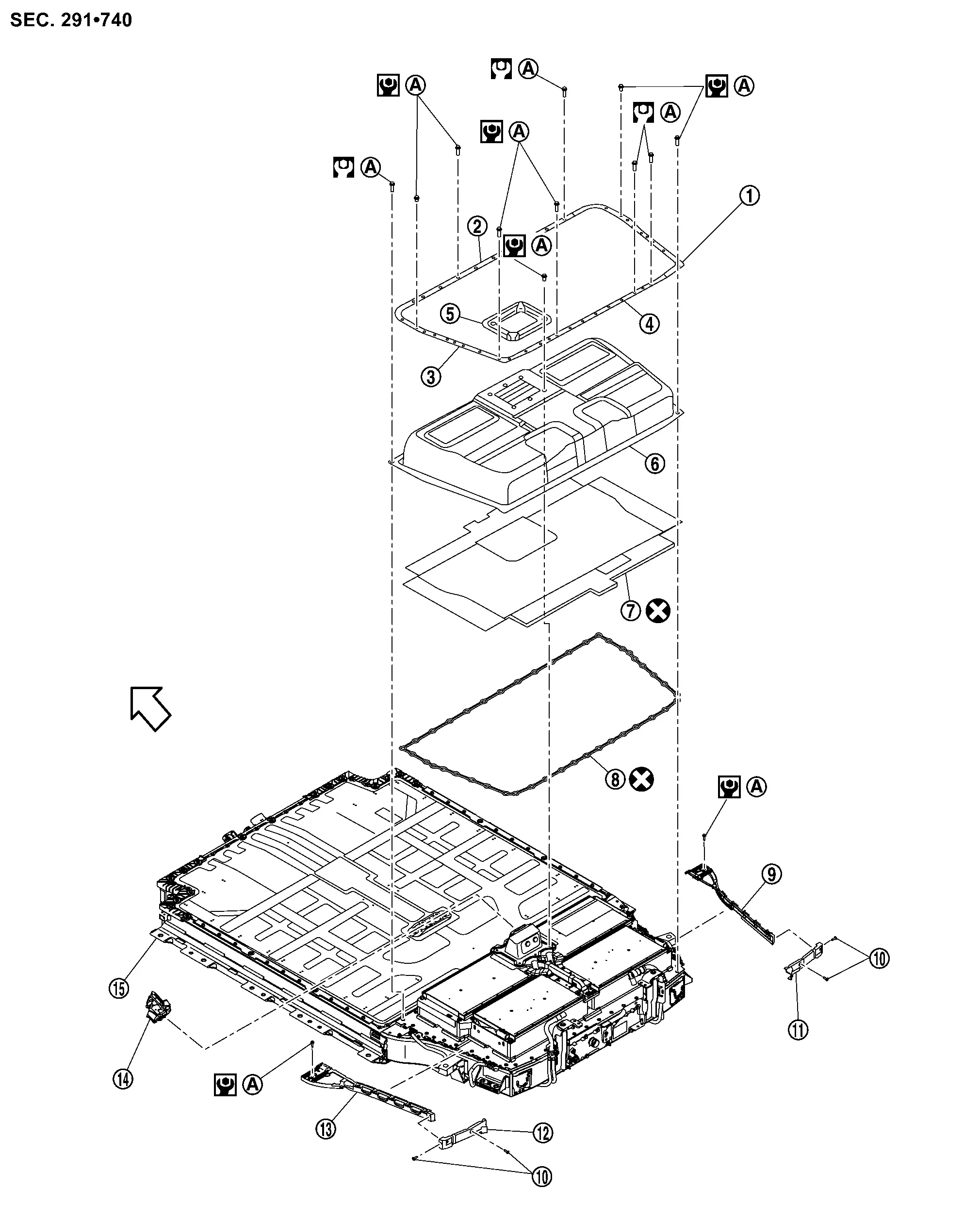
|
Retainer (RH) | |
Retainer (FR) | |
Retainer (LH) |
|
Retainer (RR) | |
Service plug retainer | |
Battery pack upper case rear |
|
Insulator cover | |
Seal | |
Resin retainer |
|
Clip | |
Resin retainer | |
Resin retainer |
|
Resin retainer | |
Service plug | |
Battery pack lower case |
|
: Comply with the assembly procedure when tightening. Removal & Installation | ||||
 |
: Nissan Ariya Vehicle front | ||||
 |
: Always replace after every disassembly. | ||||
|
: N·m (kg-m, in-lb) | ||||
BATTERY PACK UPPER CASE FRONT
|
Resin retainer | |
Resin retainer | |
Resin retainer |
|
Retainer | |
Retainer | |
Retainer |
|
Battery pack upper case front | |
Seal | |
Seal |
|
Bracket | |
Battery pack lower case | ||
|
: Comply with the assembly procedure when tightening. Removal & Installation | ||||
|
: Nissan Ariya Vehicle front | ||||
|
: Always replace after every disassembly. | ||||
|
: N·m (kg-m, in-lb) | ||||
 , , , , , , , , , , , , , , : Indicates that the part is connected at points with same symbol in actual Nissan Ariya vehicle. : Indicates that the part is connected at points with same symbol in actual Nissan Ariya vehicle. |
|||||
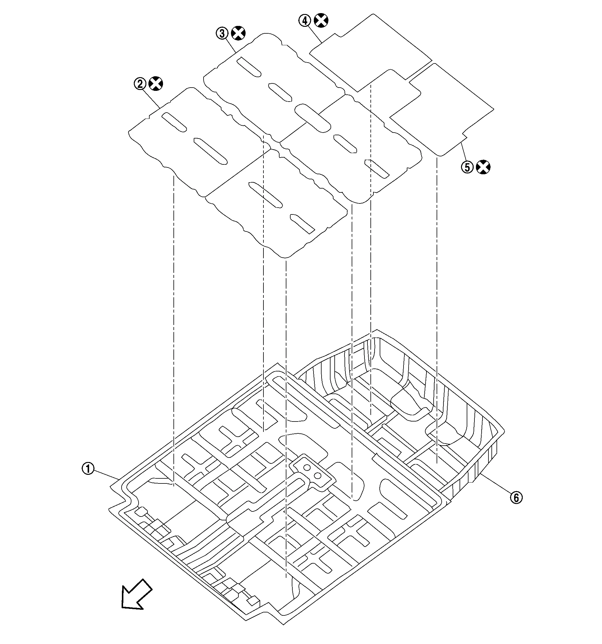
Heat shield sheet
|
Battery pack upper case | |
Heat shield sheet | |
Heat shield sheet |
|
Heat shield sheet | |
Heat shield sheet | |
Heat shield sheet |
|
: Nissan Ariya Vehicle front | ||||
|
: Always replace after every disassembly |
Removal & Installation
DANGER:Since hybrid vehicles and electric vehicles contain a high voltage battery, there is the risk of electric shock, electric leakage, or similar accidents if the high voltage component and Nissan Ariya vehicle are handled incorrectly. Be sure to follow the correct work procedures when performing inspection and maintenance.
WARNING:
-
Be sure to remove the service plug in order to shut off the high voltage circuits before performing inspection or maintenance of high voltage system harnesses and parts.
-
Be sure to put the removed service plug in pocket and carry it or store it in a tool box or other container so that another person does not accidentally connect it while work is in progress.
-
Be sure to put on insulating protective gear before beginning work on the high voltage system.
-
Clearly identify the persons responsible for high voltage work and ensure that other persons do not touch the Nissan Ariya vehicle. When not working, cover high voltage components with an anti-static cover sheet or similar item to prevent contact with other persons. Refer to HIGH VOLTAGE PRECAUTIONS : Precautions.
-
If the battery pack is to be disassembled, be sure to remove the Li-ion battery controller for preventing electric shock, fire, and damage to parts.
CAUTION:
There is the possibility of a malfunction occurring if the vehicle is changed to READY status while the service plug is removed. Therefore do not change the Nissan Ariya vehicle to READY status unless instructed to do so in the Service Manual.
ENVIRONMENT FOR LI-ION BATTERY DISASSEMBLY WORK
Must be an indoor environment.
-
The environment must utilize a shutter or other means to shut out the outside environment and prevent rain, snow, dust, or other substances from entering.
-
The environment must not cause the intrusion of sweat during work, or cause condensation to occur due to high temperature or humidity.
Metal powder, grease, and other foreign substances must not enter.
-
The indoor environment must also prevent metal powder, grease, and other foreign substances from entering due to maintenance performed on other Nissan Ariya vehicles and other sources during disassembly work.
-
During disassembly without internal work, temporarily close the battery pack upper case or cover it with an insulating cover.
The floor must be dry.
-
The floor must not be wet as a result of factors such as Nissan Ariya vehicle entry during rain or snow.
Work space
-
The work space must be approximately the size of one entire Nissan Ariya vehicle.
-
Take appropriate countermeasures so that persons other than the operator do not enter the work space, such as by placing signs indicating that disassembly work is in progress.
Standard fire fighting equipment
-
Always place a standard fire fighting equipment in the disassembly work area.
-
Depending on type of fire (Nissan Ariya vehicle or battery) use standard fire fighting equipment (water or extinguisher).
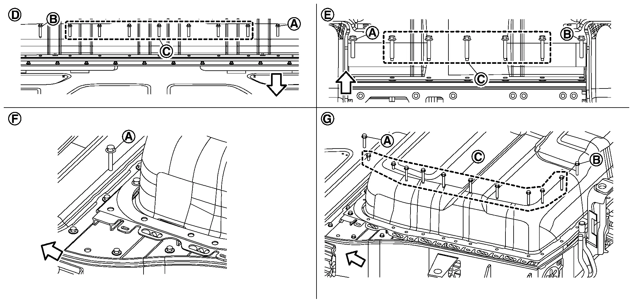
BATTERY PACK UPPER CASE REAR
REMOVAL
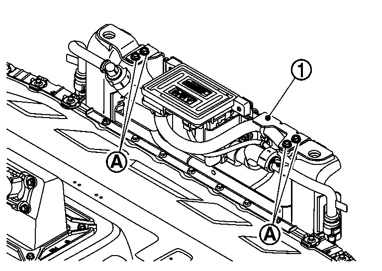
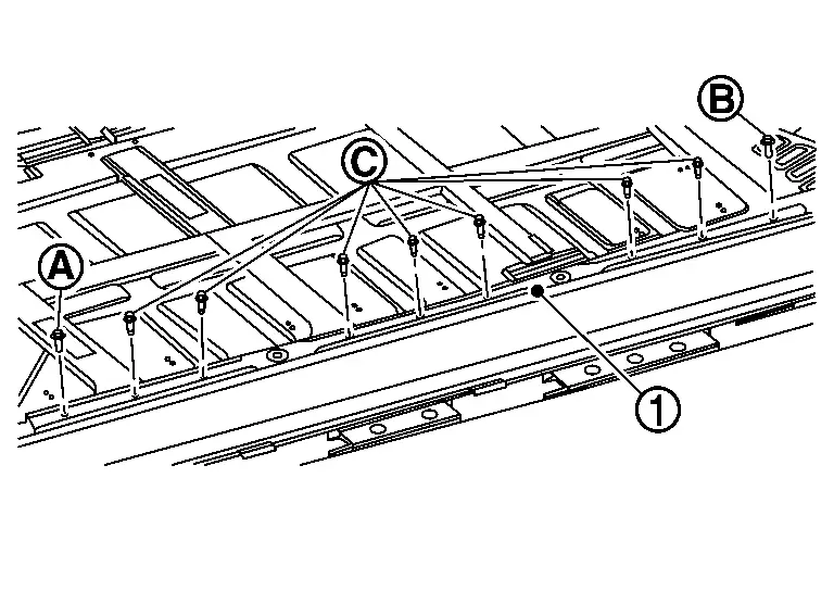
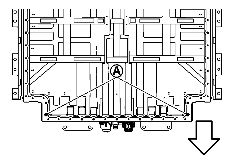
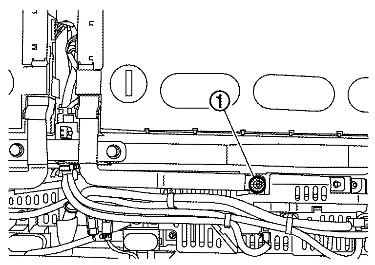
Remove tightening bolts of battery heater bracket from battery pack lower case.
WARNING:
To prevent electric shock, wear insulated protective gear.
Remove Li-ion battery cooler tube from battery pack upper floor assembly. Refer to Disassembly & Assembly.
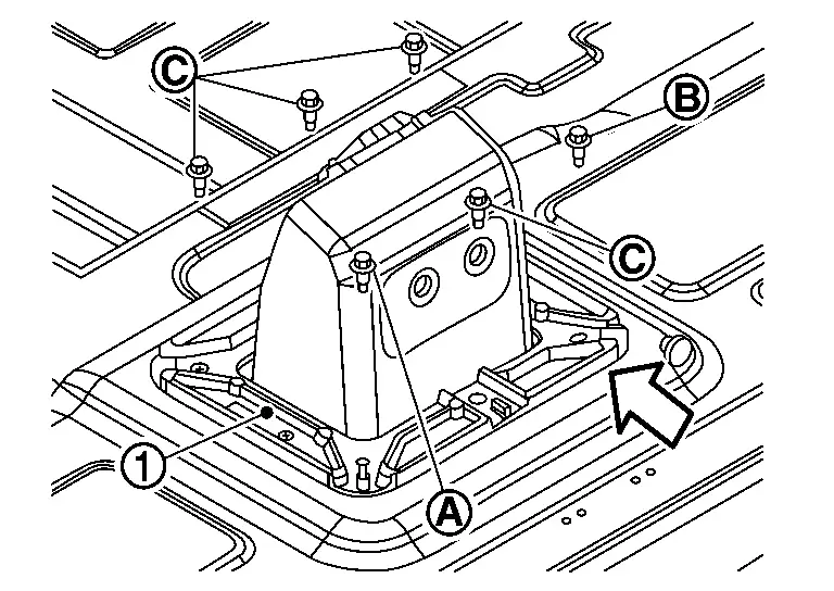
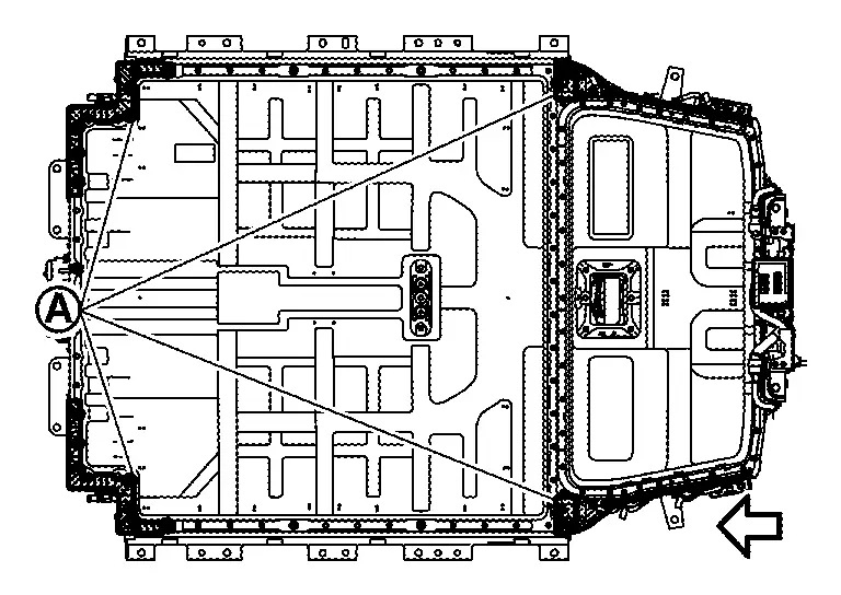
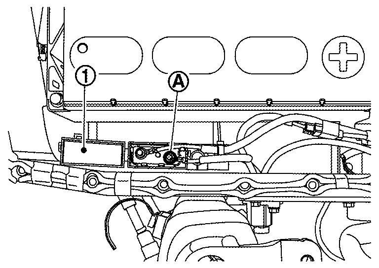
Remove service plug retainer.
|
: Battery front |
 NOTE:
NOTE:
Remove bolts in the order of →→.
WARNING:
To prevent electric shock, wear insulated protective gear.


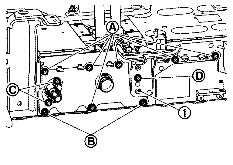
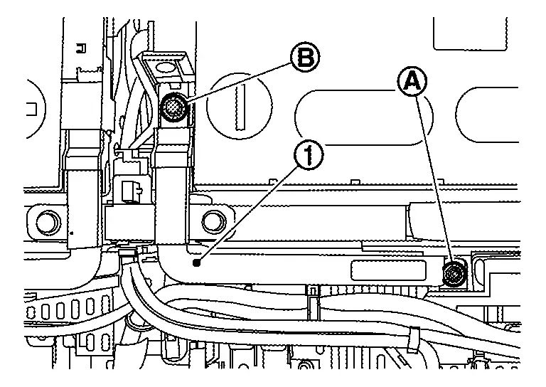
Remove left and right retainers.
NOTE:
-
The figure shows the left side.
-
Remove bolts for each retainer in the order of
→→.
WARNING:
To prevent electric shock, wear insulated protective gear.
Remove left and right resin retainer.
Remove each bolt and for each retainer (FR, RR, LH and RH).
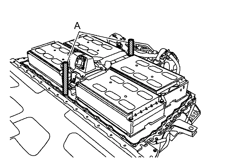
Hold both sides of the battery pack upper case to remove it.
Remove insulator cover.
Remove the seal from battery pack upper floor assembly.
Remove the seal from service plug bracket.
INSTALLATION
Check that heat shield sheet is still stuck back of battery upper case.
-
When the sheet is peeled or battery pack upper case rear is replaced, stick new heat shield sheet according to the following procedure.
CAUTION:
Work on carton box to prevent the warmed heat from escaping.
-
For the battery pack upper case rear, warm the surface where the heat shield sheet are stuck for at least 5 minutes so that the entire surface is at least 15 ℃ (59 °F).
-
Remove the release paper from the heat shield sheet, and then heat the side stuck to battery pack upper case rear for at least 1 minute so that its temperature is 15 ℃ (59 °F) or higher.
-
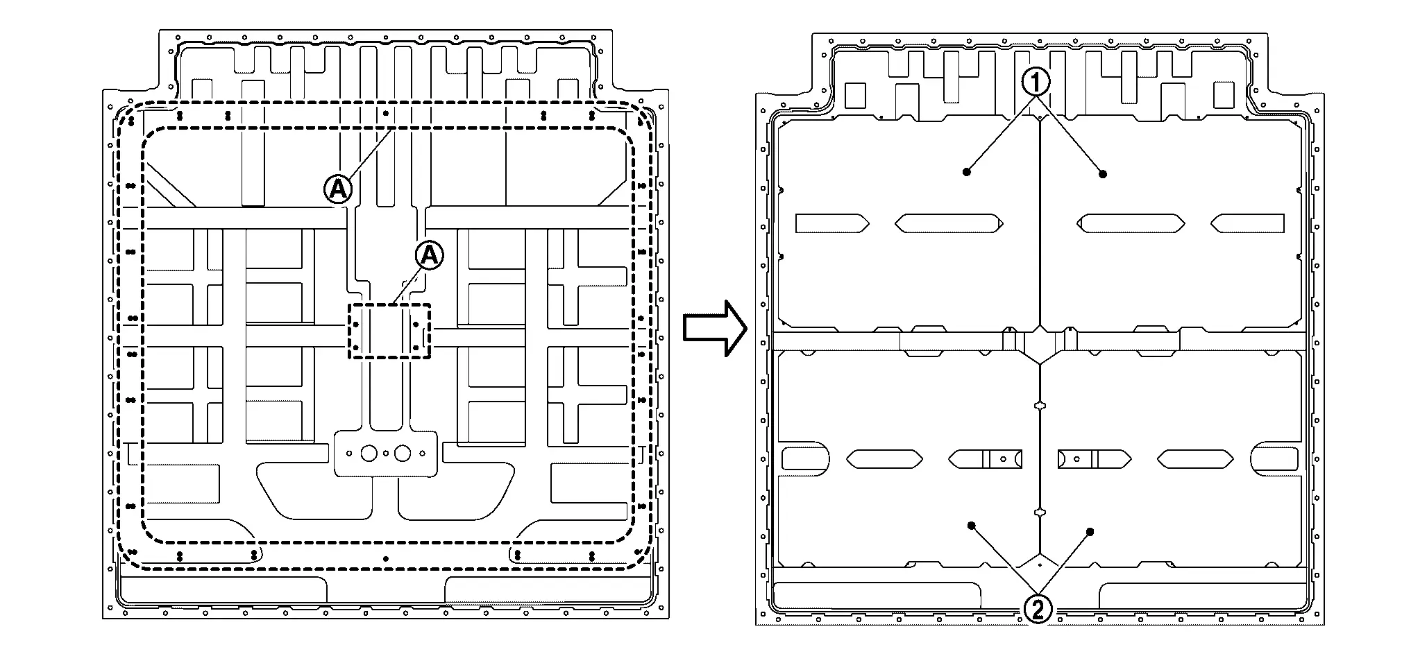
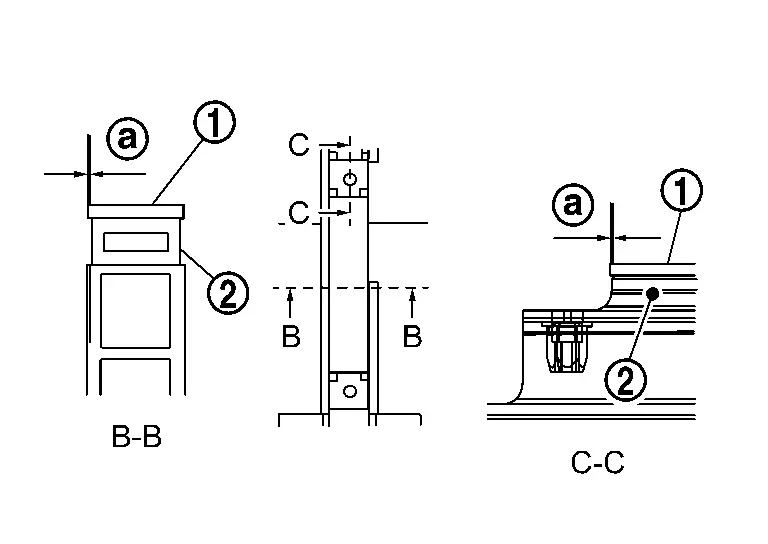
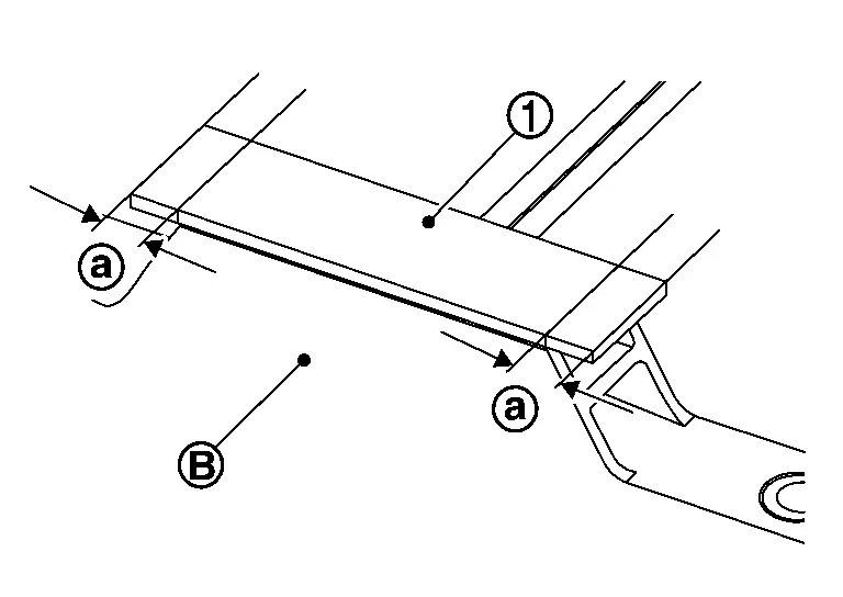
Stick the heat shield sheet
to the battery pack upper case rear as shown in the figure.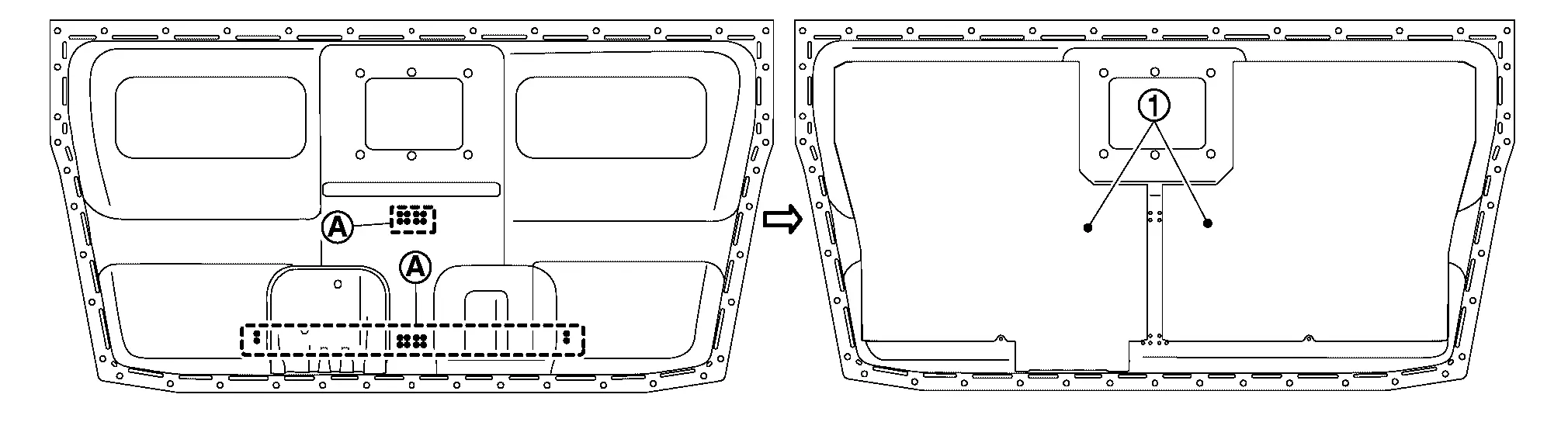
Position mark (Projection)
NOTE:
-
Stick the heat shield sheet that hides the inner position mark where two position marks are lined up.
-
Part
does not have any problem even if it gets wrinkled when sticking the heat shield sheet.
Install seal to battery pack upper floor assembly.
WARNING:
To prevent electric shock, wear insulated protective gear.
CAUTION:
The flat side of seal faces battery pack lower case.
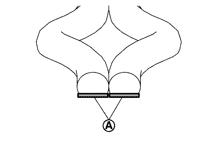
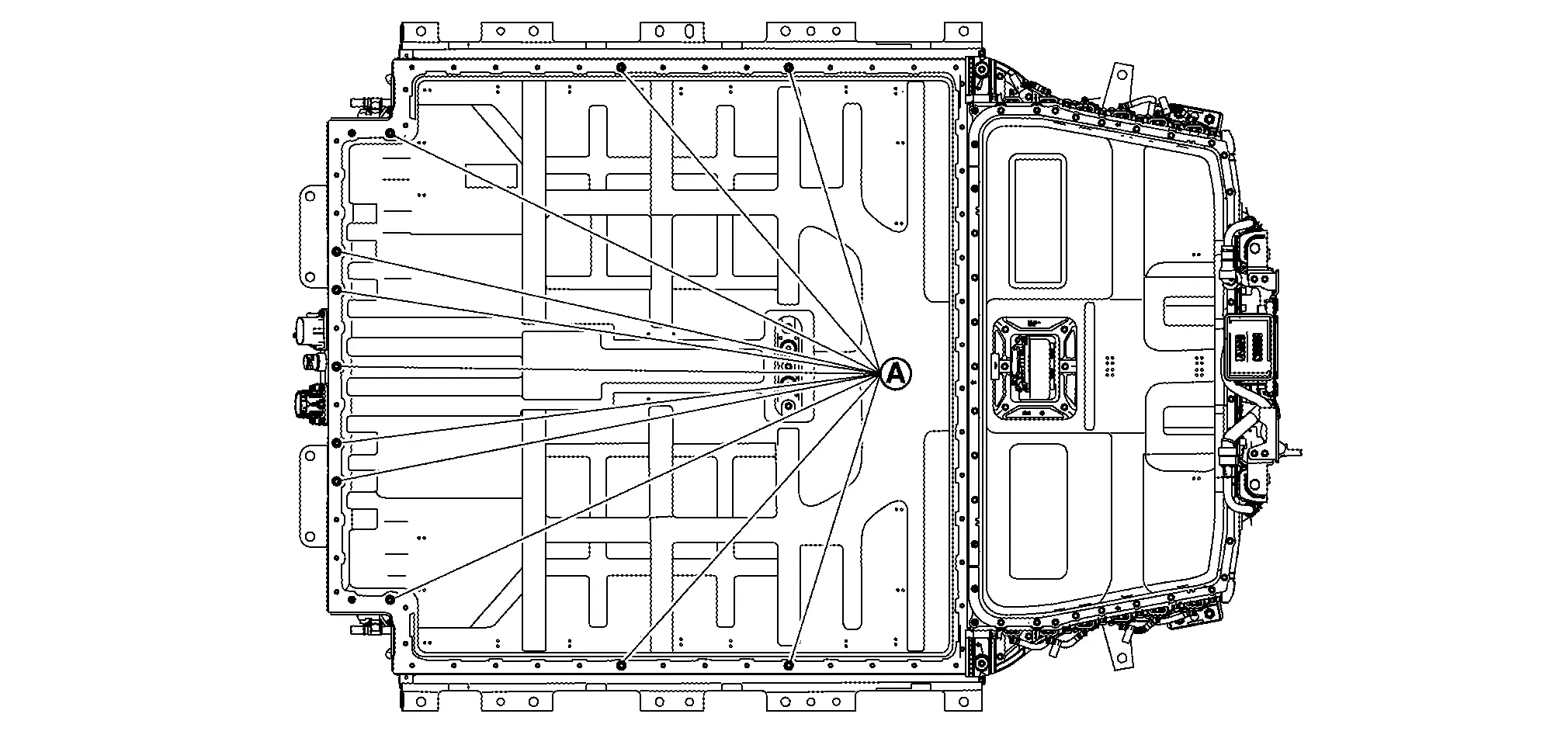
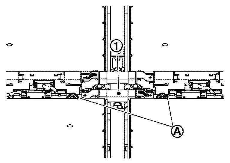
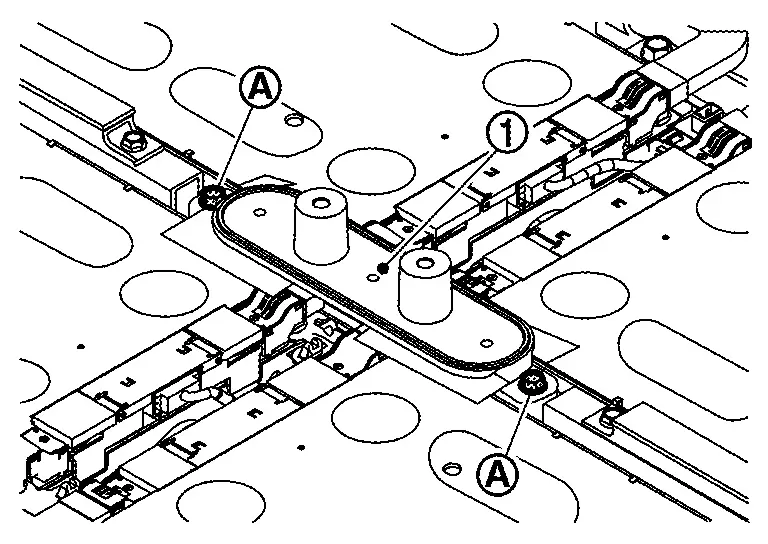
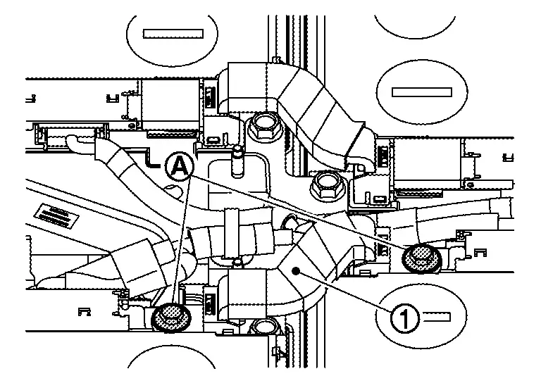
Install guide pin [SST: KV99119600 (J-53348)] (A) to the center of battery pack upper floor assembly.
WARNING:
To prevent electric shock, wear insulated protective gear.
Install insulator cover
CAUTION:
Hold the base sheet (clear) part of the insulator cover, and do not hold the form (white) and EPT sealer (black).
Install the seal of service plug bracket.
Hold both sides of the battery pack upper case to install it.
Install each bolt and for each retainer (FR, RR, LH and RH).
NOTE:
-
Tighten each retainer bolt in the order of
→→., : 11.1 N.m (1.1kg-m, 8 ft-lb) : 8.0 N.m (0.82 kg-m, 71 in-lb) : Retainer (FR) : Retainer (RR) : Both side front 
: Retainer (LH), Retainer (RH) : Battery front
WARNING:
To prevent electric shock, wear insulated protective gear.
Install left and right resin retainer.
|
: Battery front |
|
: 8.0 N.m (0.82 kg-m, 71 in-lb) |
NOTE:
-
The figure shows the left side.
-
Tighten bolts in the order of
→→.
WARNING:
To prevent electric shock, wear insulated protective gear.
Install service plug retainer.
Install Li-ion battery cooler tube to battery pack upper floor assembly. Refer to Disassembly & Assembly.
Install battery heater bracket to battery pack lower case.
BATTERY PACK UPPER CASE FRONT
REMOVAL
Remove left and right retainers .
NOTE:
-
The figure shows the left side.
-
Remove bolts for each retainer in the order of
→→.
WARNING:
To prevent electric shock, wear insulated protective gear.
Remove left and right resin retainers in the order of 3→2→1
|
: Battery front |
NOTE:
Remove bolts for each resin retainer in the order of →→.
WARNING:
To prevent electric shock, wear insulated protective gear.
Remove retainer .
|
: Battery front |
NOTE:
Remove bolts in the order of →→.
WARNING:
To prevent electric shock, wear insulated protective gear.
Remove bolt .
WARNING:
To prevent electric shock, wear insulated protective gear.
Remove bolt of backward on the battery pack upper case front.
Hold both sides of the battery pack upper case front to remove it.
WARNING:
To prevent electric shock, wear insulated protective gear.
Remove seal from battery pack lower case.
WARNING:
To prevent electric shock, wear insulated protective gear.
INSTALLATION
Check that heat shield sheet is still stuck back of battery upper case front.
-
When the sheet is peeled or battery pack upper case front is replaced, stick new heat shield sheet according to the following procedure.
CAUTION:
Work on carton box to prevent the warmed heat from escaping.
-
For the battery pack upper case front, warm the surface where the heat shield sheet are stuck for at least 5 minutes so that the entire surface is at least 15 ℃ (59 °F).
-
Remove the release paper from the heat shield sheet, and then heat the side stuck to battery pack upper case for at least 1 minute so that its temperature is 15 ℃ (59 °F)or higher.
, and to the battery pack upper case front as shown in the figure.
|
Position mark (Projection) |
NOTE:
Stick the heat shield sheet that hides the inner position mark where two position marks are lined up.
After sticking the heat shield sheet, press the whole by hands.Install seal to battery pack lower case.
WARNING:
To prevent electric shock, wear insulated protective gear.
CAUTION:
The flat side of seal faces battery pack lower case.
Hold both sides of battery pack upper case front and install it.
WARNING:
To prevent electric shock, wear insulated protective gear.
Tighten bolts .
|
: Battery front |
|
: 11.1 N.m (1.1 kg-m, 8 ft-lb) |
WARNING:
To prevent electric shock, wear insulated protective gear.
Install retainer .
|
: Battery front |
|
: 8.0 N.m (0.82 kg-m, 71 in-lb) |
NOTE:
Tighten bolts in the order of →→.
WARNING:
To prevent electric shock, wear insulated protective gear.
Tighten bolt.
|
: Battery front |
|
: 8.0 N.m (0.82 ㎏-m) |
WARNING:
To prevent electric shock, wear insulated protective gear.
Install resin retainers in the order of 1→2→3.
|
: Battery front |
|
: 8.0 N.m (0.82 kg-m, 71 in-lb) |
NOTE:
Tighten bolts of each resin retainer in the order of →→.
WARNING:
To prevent electric shock, wear insulated protective gear.
Install left and right retainers .
NOTE:
-
The figure shows the left side.
-
Tighten bolts for each retainer in the order of
→→., : 11.1 N.m (1.1 kg-m, 8 ft-lb) : 8.0 N.m (0.82 kg-m, 71 in-lb)
WARNING:
To prevent electric shock, wear insulated protective gear.
Install bolt of backward on the battery pack upper case front.
| : 8.0 N.m (0.82 kg-m, 71 in-lb) |
WARNING:
To prevent electric shock, wear insulated protective gear.
Inspection
APPEARANCE CHECK
Check resin retainer for damage.
: Battery front
CAUTION:
When resin retainer is damaged, remove battery upper case and check that no water is entering in the case.
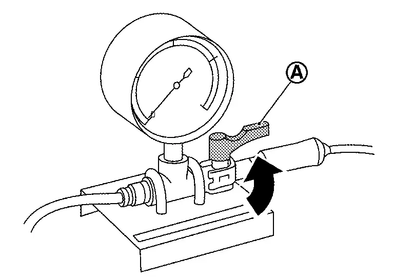
AIR LEAK INSPECTION
Remove breather and install adapter (A) of air leak tester [SST: KV99112400 (J-53357)].
WARNING:
To prevent electric shock, wear insulated protective gear.
NOTE:
Tighten wing nut by turning 6 to 8 times.
Install gauge (A) of air leak tester [SST: KV99111400 (-)].
WARNING:
To prevent electric shock, wear insulated protective gear.
CAUTION:
The gauge is a precision instrument. Be careful not to drop it when handling it.
Install service plug. Refer to HOW TO DISCONNECT HIGH VOLTAGE : Precautions.DANGER:
To prevent electric shock, wear insulated protective gear.
NOTE:
Because the service plug location is open, install the service plug for sealing the case.
Blocks high power connector and Nissan Ariya vehicle communications harness connector with vinyl tape or equivalent for preventing air leakage from connection area.
-
Use wide vinyl tape that is capable of covering all of the high power connector and Nissan Ariya vehicle communications harness connector with one strip.
-
Apply carefully so that no wrinkles in the tape occur.
WARNING:
To prevent electric shock, wear insulated protective gear.
Block breather with vinyl tape prevent air from leaking.
-
Apply carefully so that no wrinkles in the tape occur.
WARNING:
To prevent electric shock, wear insulated protective gear.
Perform battery case pressure test according to the following procedure.
WARNING:
To prevent electric shock, wear insulated protective gear.
of air leak tester.
CAUTION:
Do not operate the pump before opening the cock of air leak tester. Doing so may damage the gauge. If the pump is operated before the cock is opened, first disconnect the air pump hose to release the pressure.
Operate the air pump slowly and apply the specified test pressure in the battery pack. If the gauge pressure does not rise, or if the gauge reading fluctuates, check for the location air leakage.| Specified test pressure | : 1.6 kPa (0.016 bar, 0.0163 kg/cm2, 0.232 psi) |
CAUTION:
-
Operate the air pump carefully when applying pressure. If pressure is applied suddenly to the gauge, the gauge may be damaged.
-
Do not apply pressure of 2.0 kPa (0.02 bar, 0.0204 kg/cm2, 0.29 psi) or more to the battery case or air leak tester.
| Repair limit | : 1.4 kPa (0.014 bar, 0.0142 kg/cm2, 0.203 psi) |
NOTE:
Check for air leakage from the sound of air escaping when pressure is applied.
ELECTRIC EQUIPOTENTIAL TEST
After assembling Li-ion battery pack, remove the battery pack upper case ground bolt , then measure the resistance between the side of battery pack lower case and the seating surface of ground bolt (location of coating peeling) .
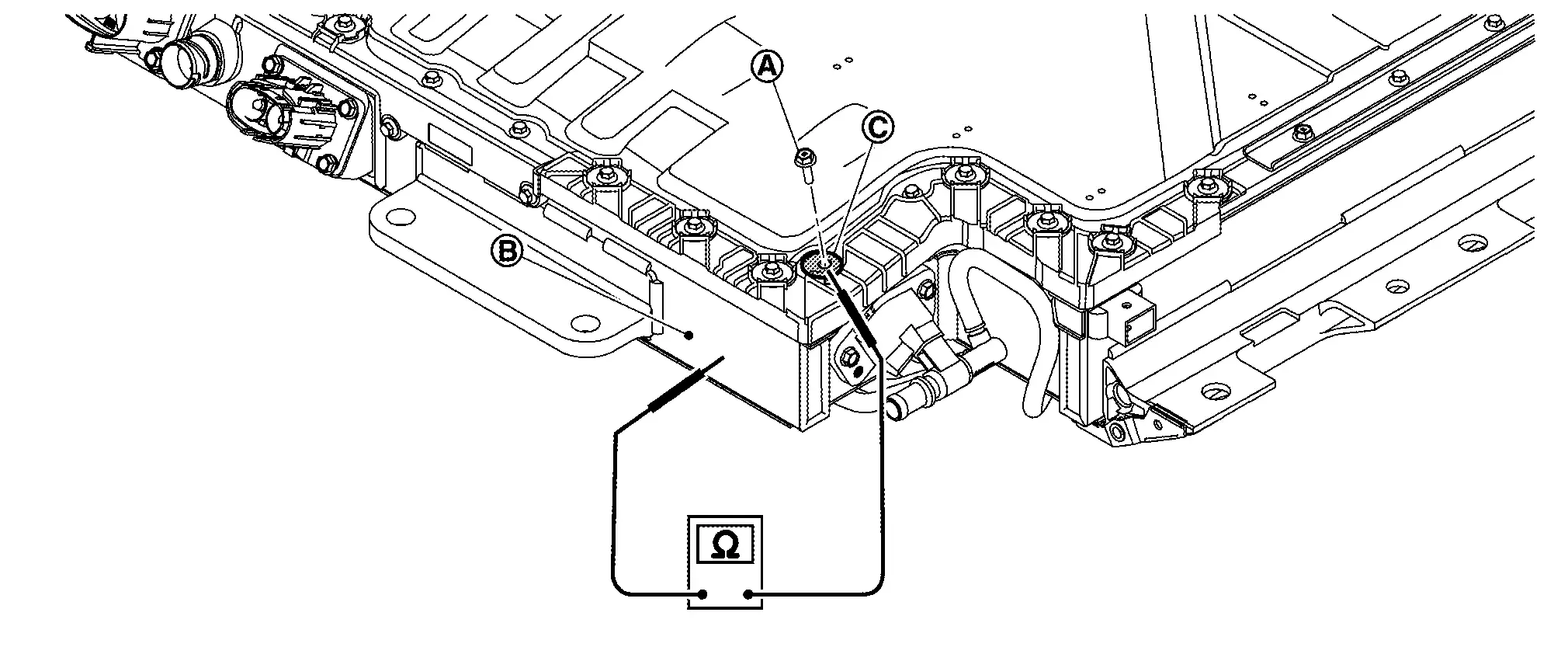
WARNING:
To prevent electric shock, wear insulated protective gear.
| Specified value | : Less than 0.1 Ω |
If the result deviates from the specified value, check the following and repair the malfunction parts.
-
Ground bolt connection condition
-
Corrosion on ground bolt mounting surface
-
Adhesion of paint, oil, dirt, or other substance on ground bolt mounting surface
After assembling Li-ion battery pack, remove the retainer ground bolt , then measure the resistance between the side of battery pack lower case and the seating surface of ground bolt (location of coating peeling) .
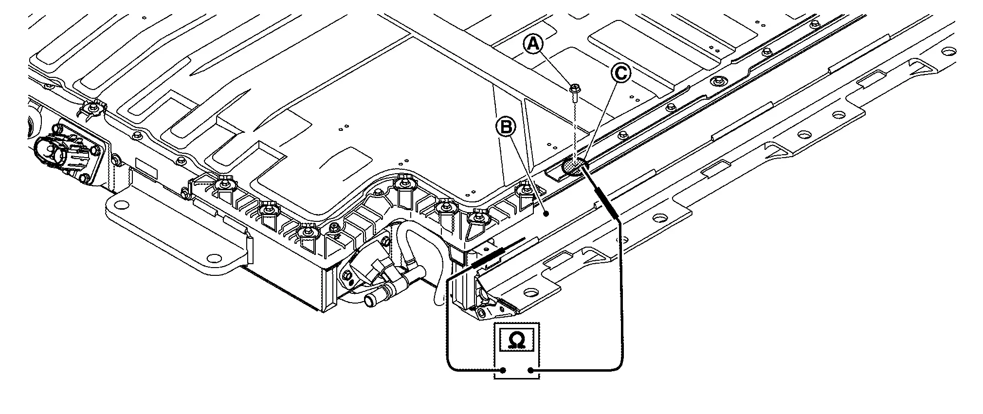
WARNING:
To prevent electric shock, wear insulated protective gear.
| Specified value | : Less than 0.1 Ω |
If the result deviates from the specified value, check the following and repair the malfunction parts.
-
Ground bolt connection condition
-
Corrosion on ground bolt mounting surface
-
Adhesion of paint, oil, dirt, or other substance on ground bolt mounting surface.
NOTE:
-
The figure shows retainer of left side.
-
Since retainers are symmetrical parts, do the same for the right retainer.
After assembling Li-ion battery pack, remove the rear retainer ground bolt , then measure the resistance between the side of battery pack lower case and the seating surface of ground bolt (location of coating peeling) .
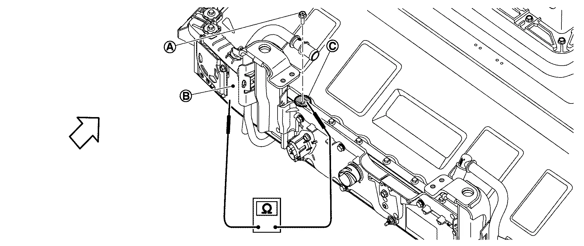
|
: Battery front |
WARNING:
To prevent electric shock, wear insulated protective gear.
| Specified value | : Less than 0.1 Ω |
If the result deviates from the specified value, check the following and repair the malfunction parts.
-
Ground bolt connection condition
-
Corrosion on ground bolt mounting surface
-
Adhesion of paint, oil, dirt, or other substance on ground bolt mounting surface.
Battery Pack Lower Case. 2wd Nissan Ariya
Exploded View
|
Battery pack lower case | |
Battery ventilation valve cover LH | |
Rear box |
|
Seal | |
Battery ventilation valve cover RH | |
Terminal block |
|
Bracket with ept sealer | |
Ept sealer | ||
|
Battery ventilation valve | ||||
|
: Nissan Ariya Vehicle front | ||||
|
: Always replace after every disassembly. | ||||
|
: N·m (kg-m, in-lb) |
Disassembly & Assembly
DANGER:Because hybrid vehicles and electric vehicles contain a high voltage battery, there is a risk of electric shock, electric leakage, or similar accidents if the Nissan Ariya vehicle is handled incorrectly. Be sure to follow the correct work procedures when performing inspection and maintenance.
WARNING:
-
Be sure to remove the service plug in order to shut off the high voltage circuits before performing inspection or maintenance of high voltage system harnesses and parts.
-
Be sure to put the removed service plug in pocket and carry it or store it in a tool box or other container so that another person does not accidentally connect it while work is in progress.
-
Be sure to put on insulating protective gear before beginning work on the high voltage system.
-
Clearly identify the persons responsible for high voltage work and ensure that other persons do not touch the Nissan Ariya vehicle. When not working, cover high voltage components with an anti-static cover sheet or similar item to prevent contact with other persons.
-
Refer to PRECAUTIONS FOR HIGH VOLTAGE : Precautions.
-
If the battery pack is to be disassembled, be sure to remove the Li-ion battery controller for preventing electric shock, fire, and damage to parts.
CAUTION:
There is the possibility of a malfunction occurring if the vehicle is changed to READY status while the service plug is removed. Therefore do not change the Nissan Ariya vehicle to READY status unless instructed to do so in the Service Manual.
ENVIRONMENT FOR LI-ION BATTERY DISASSEMBLY WORK
Must be an indoor environment.
-
The environment must utilize a shutter or other means to shut out the outside environment and prevent rain, snow, dust, or other substances from entering.
-
The environment must not cause the intrusion of sweat during work, or cause condensation to occur due to high temperature or humidity.
Metal powder, grease, and other foreign substances must not enter.
-
The indoor environment must also prevent metal powder, grease, and other foreign substances from entering due to maintenance performed on other Nissan Ariya vehicles and other sources during disassembly work.
-
During disassembly without internal work, temporarily close the battery pack upper case or cover it with an insulating cover.
The floor must be dry.
-
The floor must not be wet as a result of factors such as Nissan Ariya vehicle entry during rain or snow.
Work space
-
The work space must be approximately the size of one entire Nissan Ariya vehicle.
-
Take appropriate countermeasures so that persons other than the operator do not enter the work space, such as by placing signs indicating that disassembly work is in progress.
Standard fire fighting equipment
-
Always place a standard fire fighting equipment in the disassembly work area.
-
Depending on type of fire (Nissan Ariya vehicle or battery) use standard fire fighting equipment (water or extinguisher).
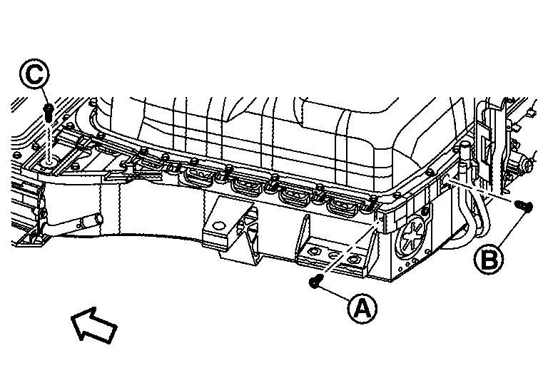
REAR BOX
Disassembly
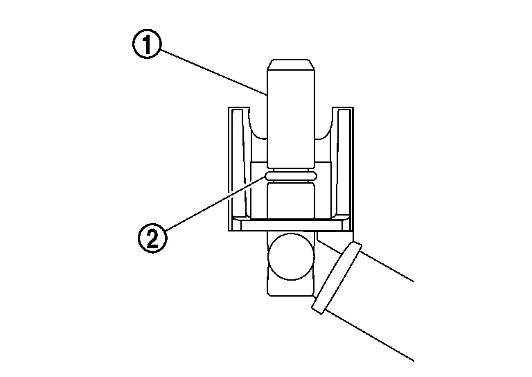
Open bus bar terminal block and remove nut .
WARNING:
To prevent electric shock, wear insulated protective gear and use insulated tools.
Remove connectors , and .
WARNING:
To prevent electric shock, wear insulated protective gear.
CAUTION:
Because there is the danger of electric shock, immediately insulate disconnected high voltage connectors with insulating tape.
Remove bolts and nuts and the remove rear box .
CAUTION:
Never loose high power bolts and .
WARNING:
To prevent electric shock, wear insulated protective gear and use insulated tools.
If necessary, remove clip and the remove Nissan Ariya vehicle communication harness (Battery PTC).
CAUTION:
Never loose bolt .
Remove seal from rear box.
ASSEMBLY
Note the following items, and assemble in the reverse order of disassembly.
DANGER:-
There is the danger of electric shock caused by contact with the terminals. Be sure to wear insulated protective gear and use insulated tools.
-
Because there is a danger of electric shock and fire, never allow bus bar to contact a wrong terminal.
-
If bus bar contacts a wrong terminal, the circuit becomes energized and a short may occur.
-
Always keep the bus bar cover closed until immediately before the installation of bus bar.
-
BATTERY VENTILATION VALVE COVER
Disassembly
Remove right or left battery ventilation valve cover .
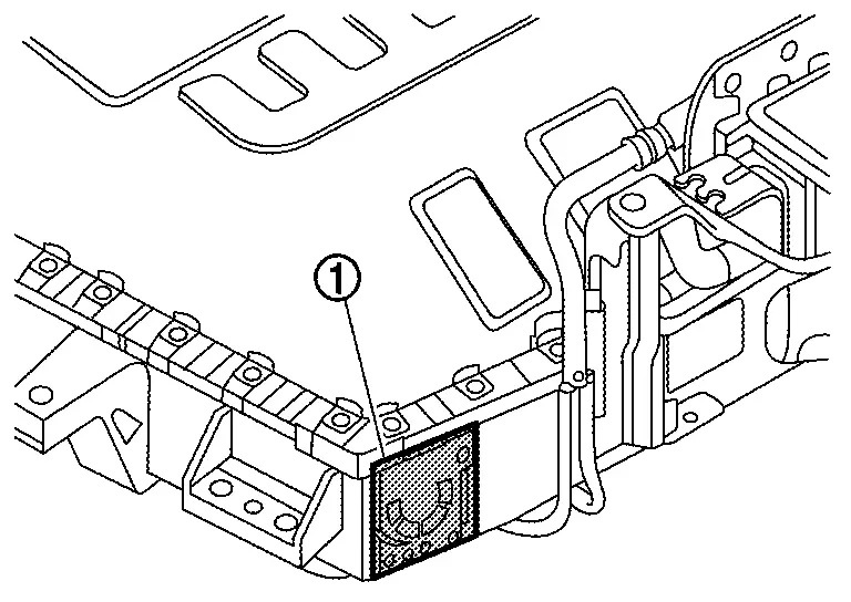
WARNING:
To prevent electric shock, wear insulated protective gear and use insulated tools.
Assembly
Install the above right or left ventilation valve cover by aligning with projection of battery pack lower case.
WARNING:
To prevent electric shock, wear insulated protective gear and use insulated tools.
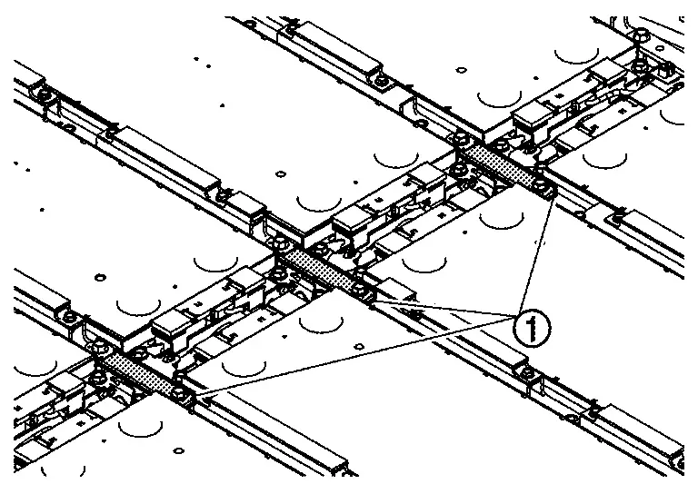
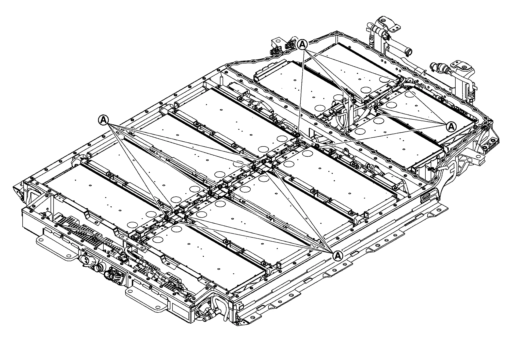
EPT SEALER REPLACEMENT
Check the figure because the procedure differs depending on the location.
| to |
: Stick to bracket |
| and |
: Stick to cross member of battery lower case. |
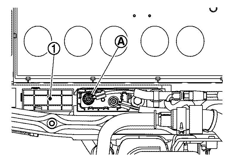
Perform parts from to according to the following procedure.Remove the bracket that requires replacement of EPT sealer.
WARNING:
To prevent electric shock, wear insulated protective gear and use insulated tools.
|
: 111 mm (4.37 in) × 23 mm (0.91 in) |
|
: 184 mm (7.24 in) × 23 mm (0.91 in) |
|
: 139 mm (5.47 in) × 23 mm (0.91 in) |
|
: 39 mm (1.54 in) × 23 mm (0.91 in) |
|
:58 mm (2.28)×23 (0.91) mm |
|
: EPT sealer |
|
: Bracket |
 |
: 0.5 mm (0.020 in) |
CAUTION:
Do not deviate from the position of EPR seal shown in the figure.
Hold EPT seal firmly with the ball of fingers.
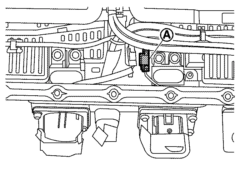
Perform parts from and according to the following procedure.
WARNING:
To prevent electric shock, wear insulated protective gear.
|
: 150 mm (5.91 in) × 26 mm (1.02 in) |
|
: 100 mm (3.94 in) × 26 mm (1.02 in) |
.
|
: EPT sealer |
|
: 10 mm (0.39 in) |
CAUTION:
Do not deviate from the position of EPR seal shown in the figure.
NOTE:
-
Since the work is done with insulated gloves,
are used as dedicated handles. -
Bend handles
down and stick them to the inclined parts.
Service Plug Bracket Nissan Ariya 2023
Exploded View
REMOVAL
|
Seal | |
Service plug bracket | |
Breather |
|
: Nissan Ariya Vehicle front | ||||
|
: Always replace after every disassembly. | ||||
|
: N·m (kg-m, in-lb) |
DISASSEMBLY
NOTE:
The size of service plug switch differs depends on Li-ion Battery specification. Remove the service plug and confirm its form.
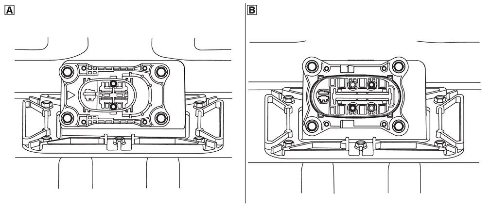
 : TYPE A
 : TYPE B
TYPE A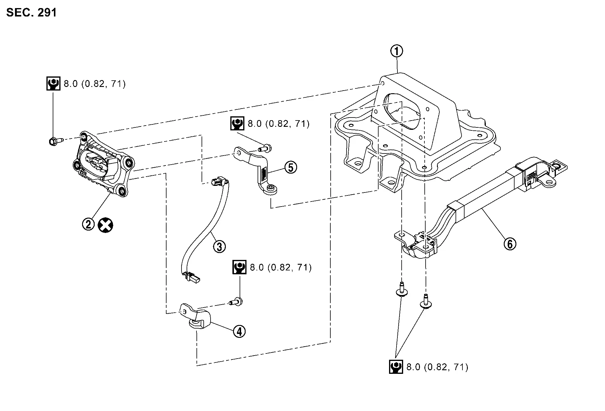
|
Service plug bracket | |
Service plug switch | |
Engagement detection switch (service plug) harness |
|
Busbar 14 | |
Busbar 13 | |
Busbar 12 |
|
: Always replace after every disassembly. | ||||
|
: N·m (kg-m, in-lb) |
TYPE B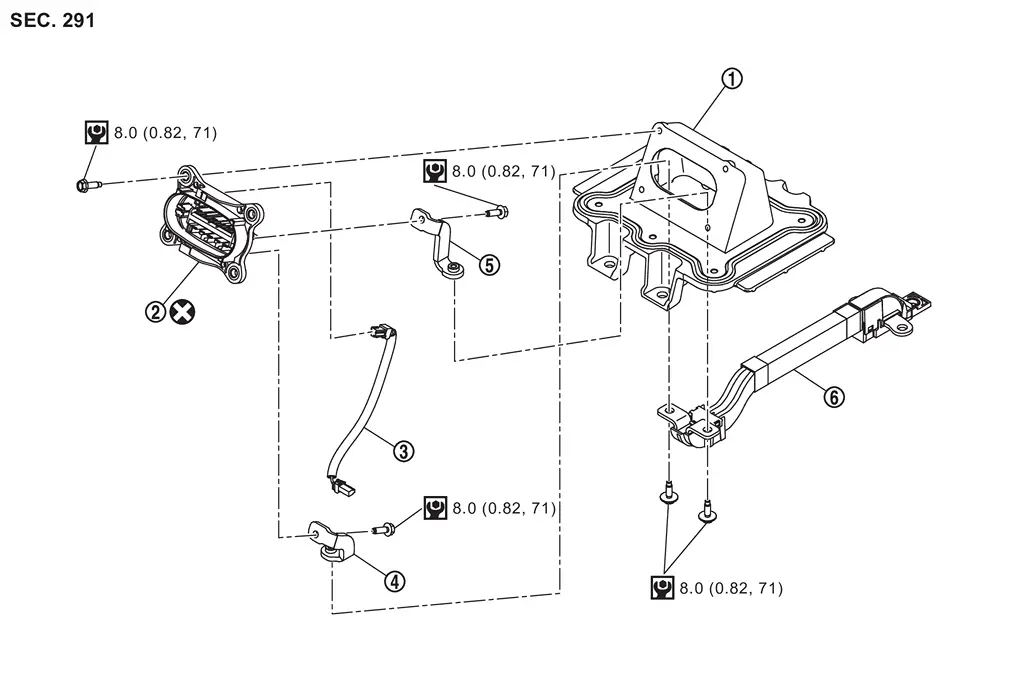
|
Service plug bracket | |
Service plug switch | |
Engagement detection switch (service plug) harness |
|
Busbar 14 | |
Busbar 13 | |
Busbar 12 |
|
: Always replace after every disassembly. | ||||
|
: N·m (kg-m, in-lb) |
Disassembly & Assembly
DANGER:Because hybrid vehicles and electric vehicles contain a high voltage battery, there is a risk of electric shock, electric leakage, or similar accidents if the Nissan Ariya vehicle is handled incorrectly. Be sure to follow the correct work procedures when performing inspection and maintenance.
WARNING:
-
Be sure to remove the service plug in order to shut off the high voltage circuits before performing inspection or maintenance of high voltage system harnesses and parts.
-
Be sure to put the removed service plug in pocket and carry it or store it in a tool box or other container so that another person does not accidentally connect it while work is in progress.
-
Be sure to put on insulating protective gear before beginning work on the high voltage system.
-
Clearly identify the persons responsible for high voltage work and ensure that other persons do not touch the Nissan Ariya vehicle. When not working, cover high voltage components with an anti-static cover sheet or similar item to prevent contact with other persons.
-
Refer to PRECAUTIONS FOR HIGH VOLTAGE : Precautions.
-
If the battery pack is to be disassembled, be sure to remove the Li-ion battery controller for preventing electric shock, fire, and damage to parts.
CAUTION:
There is the possibility of a malfunction occurring if the vehicle is changed to READY status while the service plug is removed. Therefore do not change the Nissan Ariya vehicle to READY status unless instructed to do so in the Service Manual.
ENVIRONMENT FOR LI-ION BATTERY DISASSEMBLY WORK
Must be an indoor environment.
-
The environment must utilize a shutter or other means to shut out the outside environment and prevent rain, snow, dust, or other substances from entering.
-
The environment must not cause the intrusion of sweat during work, or cause condensation to occur due to high temperature or humidity.
Metal powder, grease, and other foreign substances must not enter.
-
The indoor environment must also prevent metal powder, grease, and other foreign substances from entering due to maintenance performed on other Nissan Ariya vehicles and other sources during disassembly work.
-
During disassembly without internal work, temporarily close the battery pack upper case or cover it with an insulating cover.
The floor must be dry.
-
The floor must not be wet as a result of factors such as Nissan Ariya vehicle entry during rain or snow.
Work space
-
The work space must be approximately the size of one entire Nissan Ariya vehicle.
-
Take appropriate countermeasures so that persons other than the operator do not enter the work space, such as by placing signs indicating that disassembly work is in progress.
Standard fire fighting equipment
-
Always place a standard fire fighting equipment in the disassembly work area.
-
Depending on type of fire (Nissan Ariya vehicle or battery) use standard fire fighting equipment (water or extinguisher).
Disassembly
Remove battery pack upper rear. Refer to Removal & Installation.
Remove the bolt of busbar 12 and .
|
: Battery front |
WARNING:
To prevent electric shock, wear insulated protective gear and use insulated tools.
Remove interlock detecting switch (Service plug) harness connector .
|
: Battery front |
WARNING:
To prevent electric shock, wear insulated protective gear.
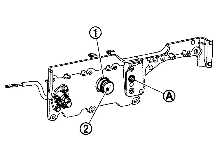
Remove nuts of service plug bracket.
Remove service plug bracket.
Remove seal from service plug bracket.
Remove bolts and remove busbar 12 from busbar 13 and busbar 14.
Remove bolts .
: Service plug
Remove service plug from service bracket .
Remove interlock detecting switch (Service plug) harness  , busbar 13
  and busbar 14 from service plug .
: Bolts
Assembly
Note the following items, and assemble in the reverse order of disassembly.
DANGER:-
There is the danger of electric shock caused by contact with the terminals. Be sure to wear insulated protective gear and use insulated tools.
-
Because there is a danger of electric shock and fire, never allow bus bar to contact a wrong terminal.
-
If bus bar contacts a wrong terminal, the circuit becomes energized and a short may occur.
-
Always keep the bus bar cover closed until immediately before the installation of bus bar.
-
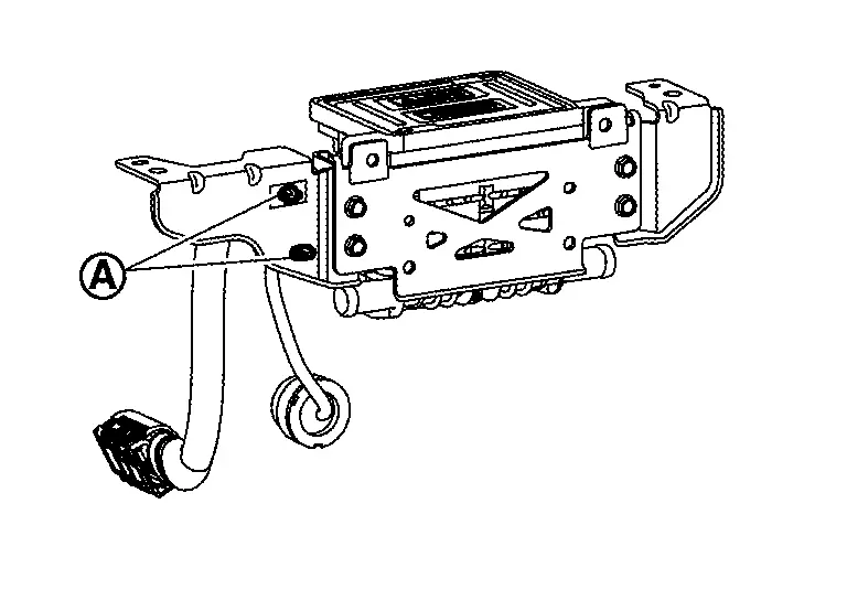
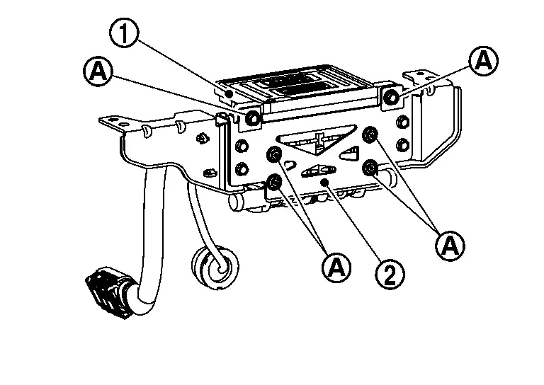
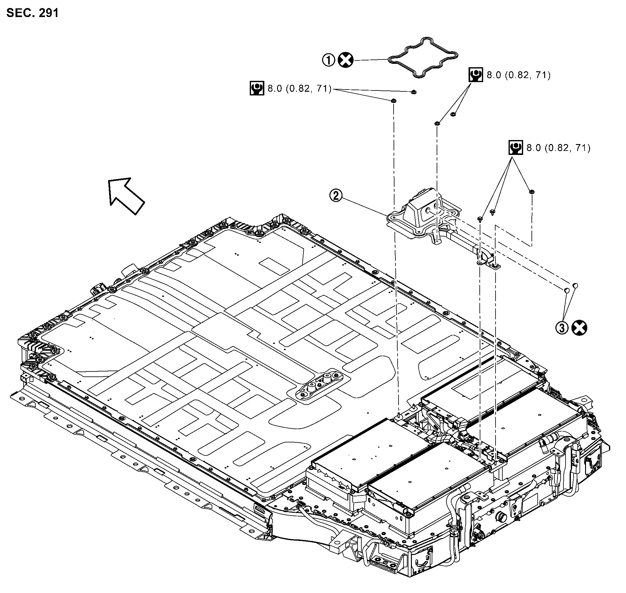
Li-Ion Battery Controller Nissan Ariya 2026
Exploded View
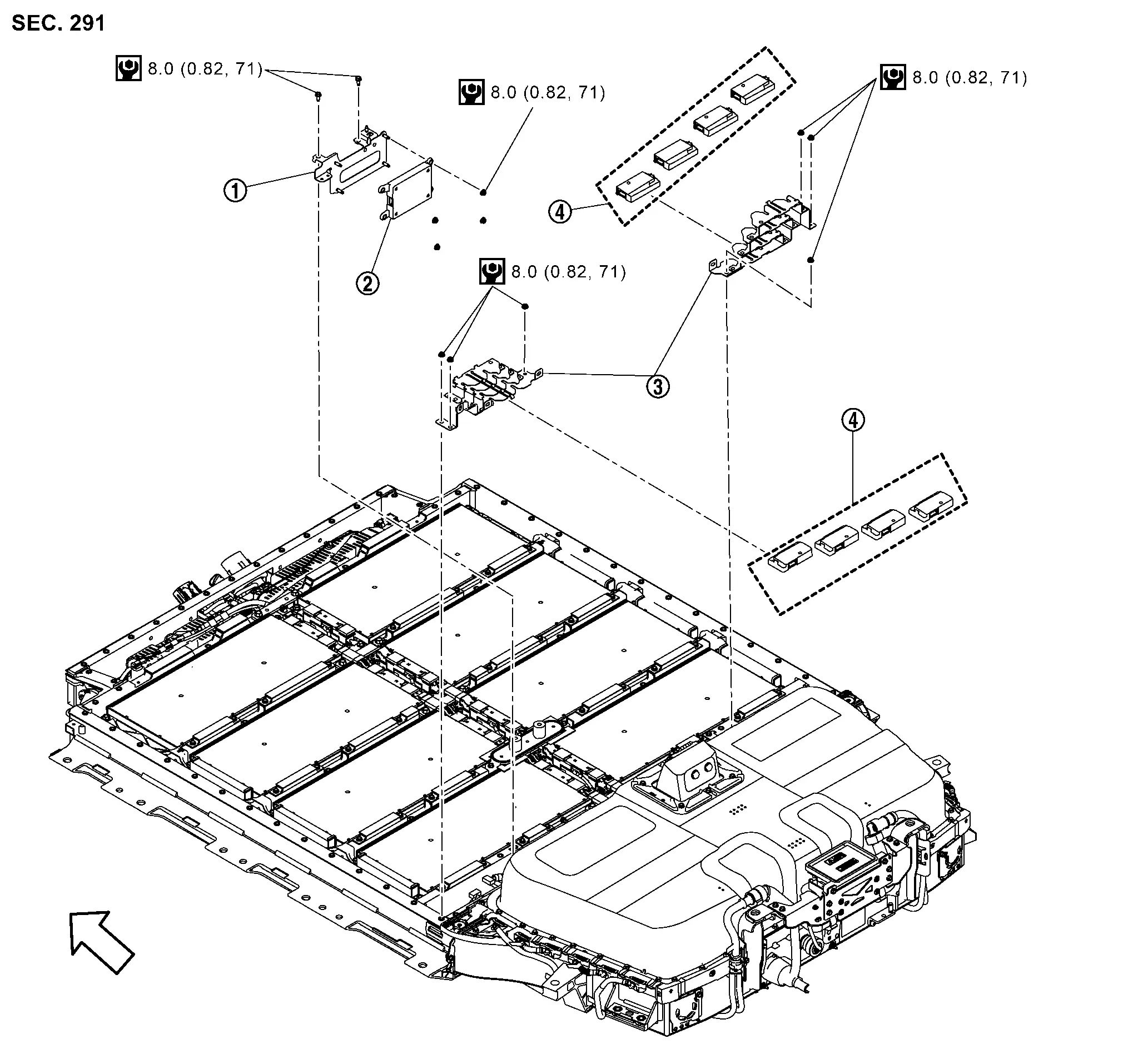
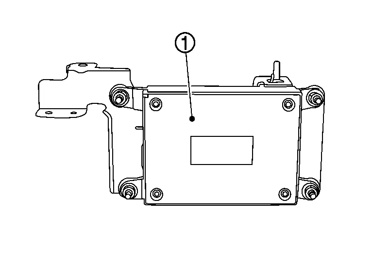
|
Bracket | |
Li-ion battery controller | |
Bracket |
|
Cell controller | ||||
|
: Nissan Ariya Vehicle front | ||||
|
: N·m (kg-m, in-lb) |
Removal & Installation
DANGER:Because hybrid vehicles and electric vehicles contain a high voltage battery, there is a risk of electric shock, electric leakage, or similar accidents if the Nissan Ariya vehicle is handled incorrectly. Be sure to follow the correct work procedures when performing inspection and maintenance.
WARNING:
-
Be sure to remove the service plug in order to shut off the high voltage circuits before performing inspection or maintenance of high voltage system harnesses and parts.
-
Be sure to put the removed service plug in pocket and carry it or store it in a tool box or other container so that another person does not accidentally connect it while work is in progress.
-
Be sure to put on insulating protective gear before beginning work on the high voltage system.
-
Clearly identify the persons responsible for high voltage work and ensure that other persons do not touch the Nissan Ariya vehicle. When not working, cover high voltage components with an anti-static cover sheet or similar item to prevent contact with other persons.
-
Refer to PRECAUTIONS FOR HIGH VOLTAGE : Precautions.
-
If the battery pack is to be disassembled, be sure to remove the Li-ion battery controller for preventing electric shock, fire, and damage to parts.
CAUTION:
There is the possibility of a malfunction occurring if the vehicle is changed to READY status while the service plug is removed. Therefore do not change the Nissan Ariya vehicle to READY status unless instructed to do so in the Service Manual.
ENVIRONMENT FOR LI-ION BATTERY DISASSEMBLY WORK
Must be an indoor environment.
-
The environment must utilize a shutter or other means to shut out the outside environment and prevent rain, snow, dust, or other substances from entering.
-
The environment must not cause the intrusion of sweat during work, or cause condensation to occur due to high temperature or humidity.
Metal powder, grease, and other foreign substances must not enter.
-
The indoor environment must also prevent metal powder, grease, and other foreign substances from entering due to maintenance performed on other Nissan Ariya vehicles and other sources during disassembly work.
-
During disassembly without internal work, temporarily close the battery pack upper case or cover it with an insulating cover.
The floor must be dry.
-
The floor must not be wet as a result of factors such as Nissan Ariya vehicle entry during rain or snow.
Work space
-
The work space must be approximately the size of one entire Nissan Ariya vehicle.
-
Take appropriate countermeasures so that persons other than the operator do not enter the work space, such as by placing signs indicating that disassembly work is in progress.
Standard fire fighting equipment
-
Always place a standard fire fighting equipment in the disassembly work area.
-
Depending on type of fire (Nissan Ariya vehicle or battery) use standard fire fighting equipment (water or extinguisher).
LI-ION BATTERY CONTROLLER
Disassembly
CAUTION:
When replace Li-ion battery controller, perform necessary work according to the procedure of "BATTERY PACK UPPER CASE : Removal & Installation". Refer to Work Item List.
Remove battery pack upper case front. Refer to Removal & Installation.
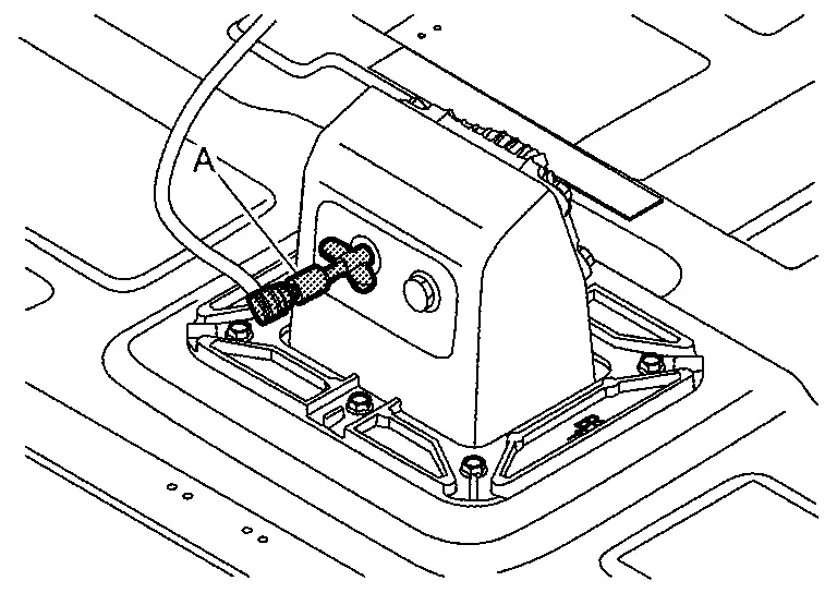
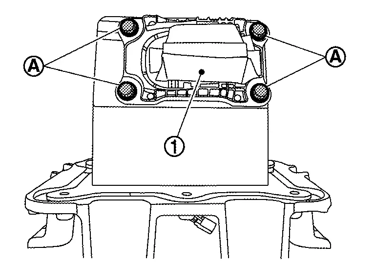
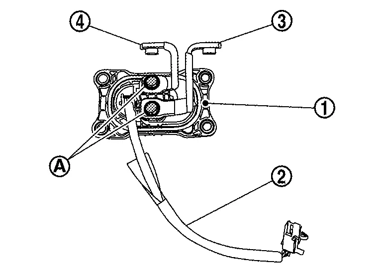
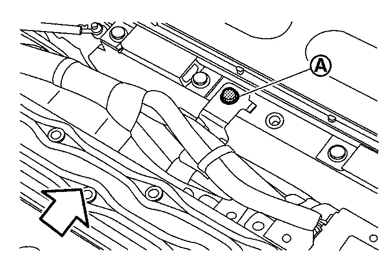
Remove nut of cable .
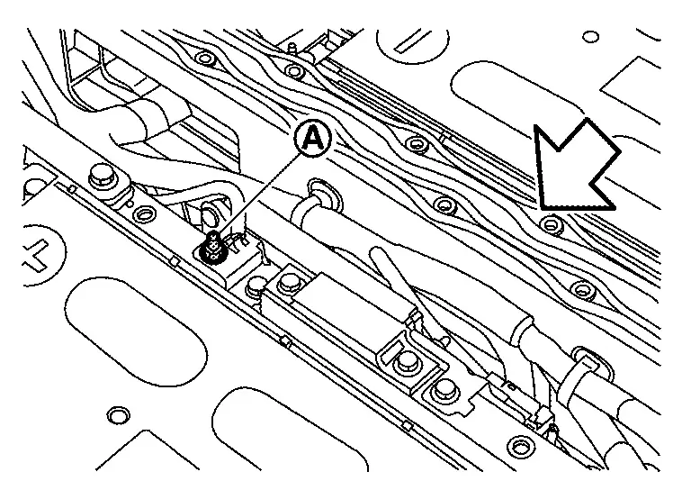
|
: Battery front |
WARNING:
To prevent electric shock, wear insulated protective gear and use insulated tools.
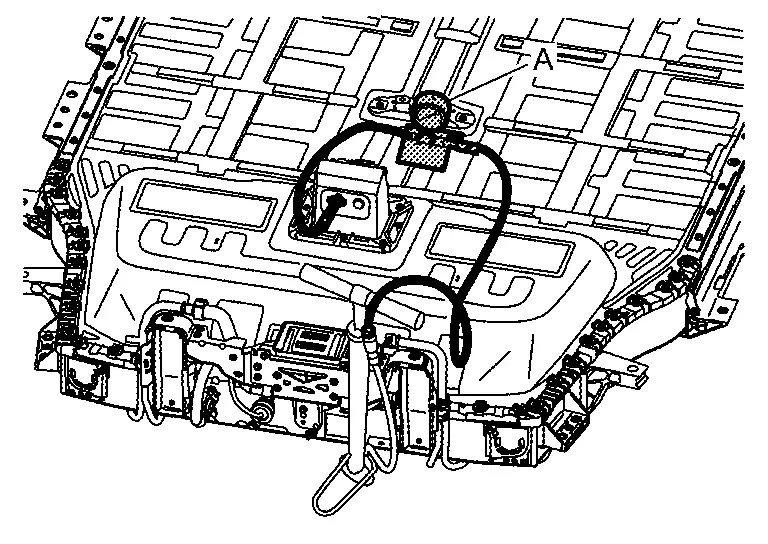
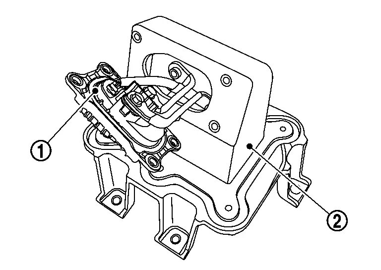
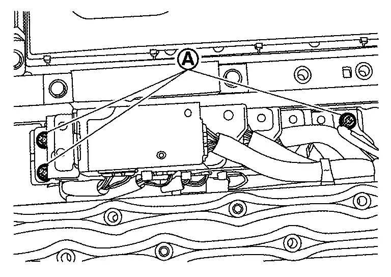
Remove the bolt of bracket.
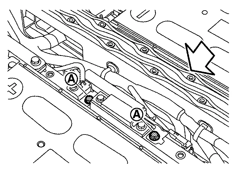
|
: Battery front |
WARNING:
To prevent electric shock, wear insulated protective gear and use insulated tools.
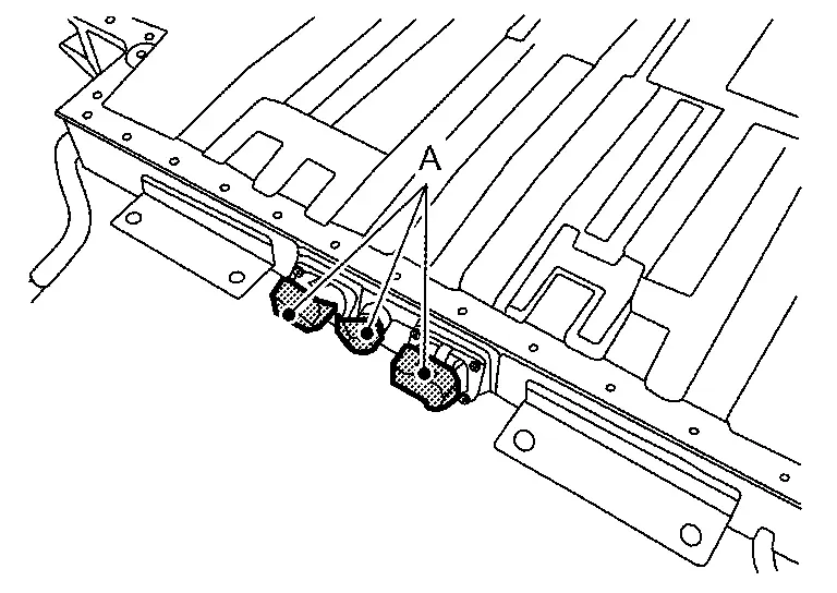
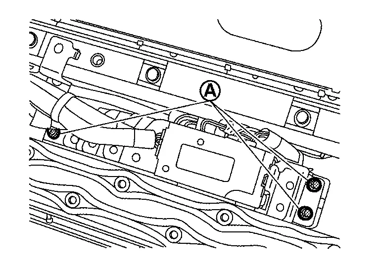
Disconnect the harness connector .
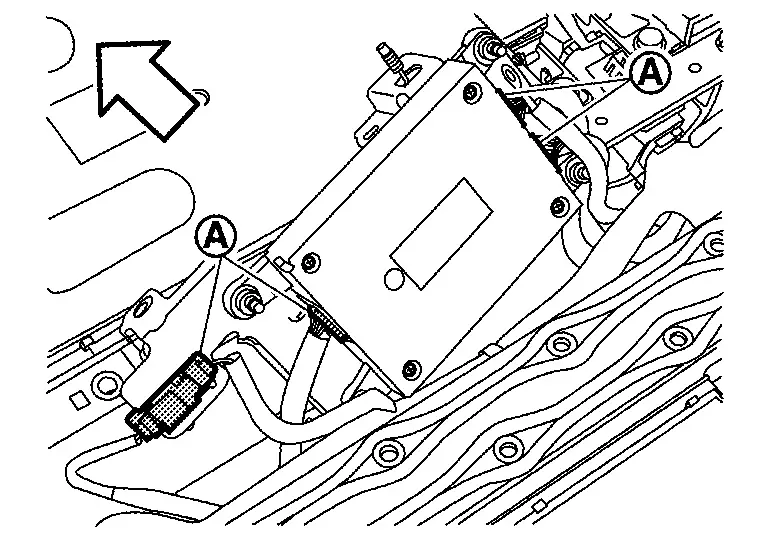
|
: Battery front |
WARNING:
To prevent electric shock, wear insulated protective gear.
CAUTION:
Because there is the danger of electric shock, immediately insulate removed connectors with insulating tape.
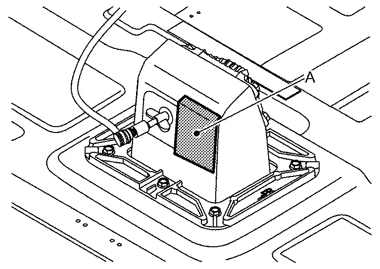
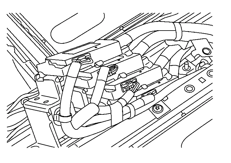
Remove Li-ion battery controller from bracket.
Assembly
Note the following items, and assemble in the reverse order of disassembly.
DANGER:-
There is the danger of electric shock caused by contact with the terminals. Be sure to wear insulated protective gear and use insulated tools.
-
Because there is a danger of electric shock and fire, never allow bus bar to contact a wrong terminal.
-
If bus bar contacts a wrong terminal, the circuit becomes energized and a short may occur.
-
Always keep the bus bar cover closed until immediately before the installation of bus bar.
-
CELL CONTROLLER (LEFT SIDE)
DISASSEMBLY
Remove battery pack upper case front. Refer to Removal & Installation.
Remove Li-ion battery controller with bracket.
WARNING:
To prevent electric shock, wear insulated protective gear and use insulated tools.
CAUTION:
Because there is the danger of electric shock, immediately insulate removed connectors with insulating tape.
Remove nut on the bracket.
WARNING:
To prevent electric shock, wear insulated protective gear and use insulated tools.
Disconnect the harness connector from cell controller.
WARNING:
To prevent electric shock, wear insulated protective gear.
CAUTION:
Because there is the danger of electric shock, immediately insulate removed connectors with insulating tape.
Disconnect the cell controller from bracket.
Assembly
Note the following items, and assemble in the reverse order of disassembly.
DANGER:-
There is the danger of electric shock caused by contact with the terminals. Be sure to wear insulated protective gear and use insulated tools.
-
There two types of cell controller harnesses for high voltage and low voltage. When inserting high voltage harness connector to low voltage system, it may cause fire or damage parts. Carefully avoid mistake when inserting connectors.
CELL CONTROLLER (RIGHT SIDE)
DISASSEMBLY
Remove battery pack upper case front. Refer to Removal & Installation.
Remove bolt on the bracket.
WARNING:
To prevent electric shock, wear insulated protective gear and use insulated tools.
|
: Battery front |
Remove nut on the bracket.
WARNING:
To prevent electric shock, wear insulated protective gear and use insulated tools.
Disconnect the harness connector from cell controller.
WARNING:
To prevent electric shock, wear insulated protective gear.
CAUTION:
Because there is the danger of electric shock, immediately insulate removed connectors with insulating tape.
Remove cell controller from the bracket.
Assembly
Note the following items, and assemble in the reverse order of disassembly.
DANGER:-
There is the danger of electric shock caused by contact with the terminals. Be sure to wear insulated protective gear and use insulated tools.
-
There two types of cell controller harnesses for high voltage and low voltage. When inserting high voltage harness connector to low voltage system, it may cause fire or damage parts. Carefully avoid mistake when inserting connectors.
Busbar. 2wd Nissan Ariya first Gen
Exploded View
DISASSEMBLY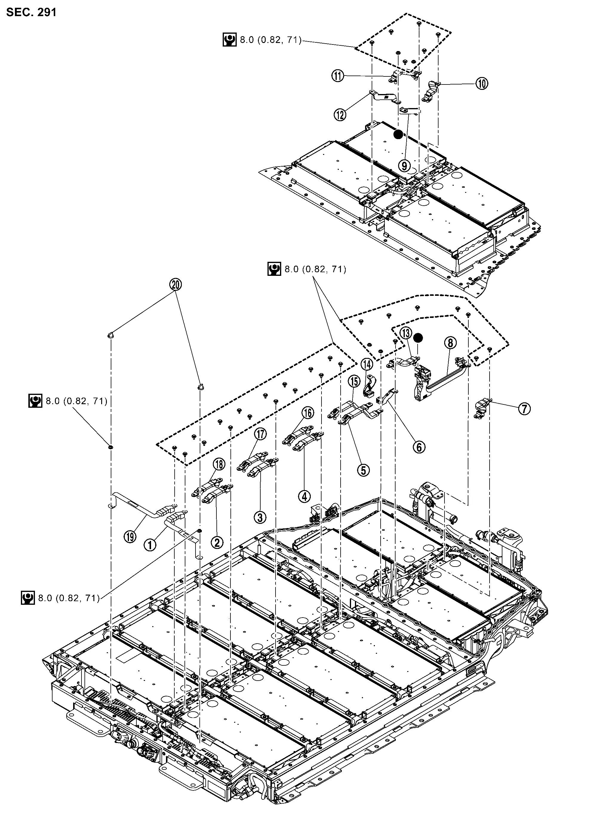
|
Busbar 2 | |
Busbar 3 | |
Busbar 4 |
|
Busbar 5 | |
Busbar 6 | |
Busbar 7 |
|
Busbar 8 | |
Busbar 9 | |
Busbar 10 |
|
Busbar 11 | |
Busbar 15 | |
Busbar 16 |
|
Busbar 17 | |
Busbar 18 | |
Busbar 19 |
|
Busbar 20 | |
Busbar 21 | |
Busbar 22 |
|
Busbar 23 | |
Nut cap | ||
|
: N·m (kg-m, in-lb) |
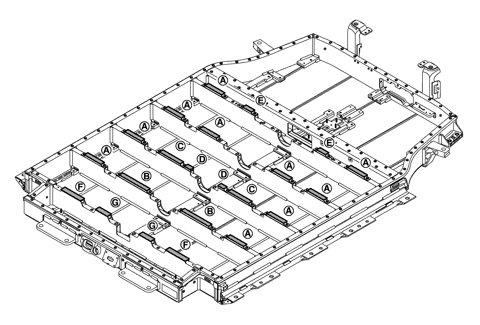
BUSBAR LAYOUT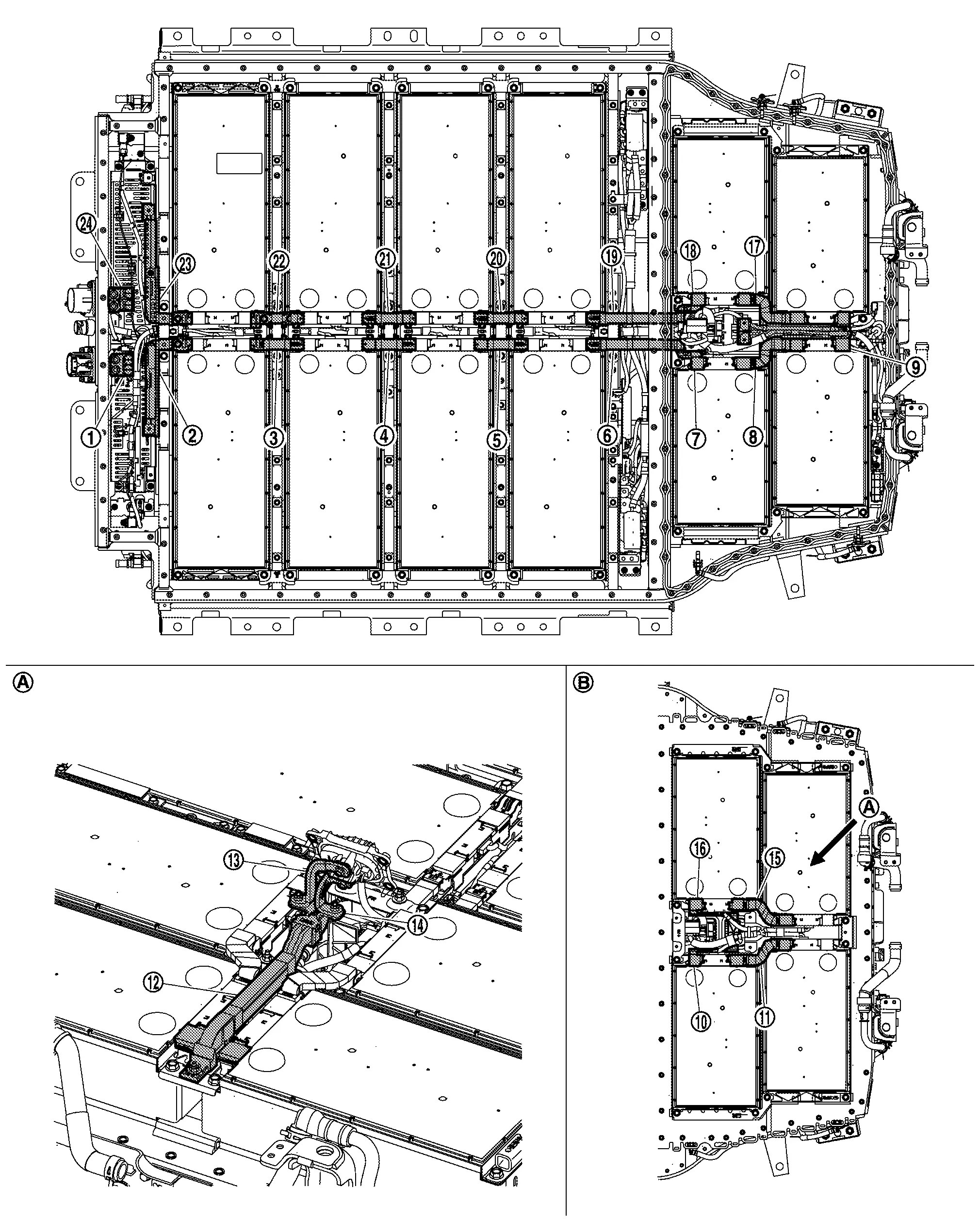
|
Busbar 1 | |
Busbar 2 | |
Busbar 3 |
|
Busbar 4 | |
Busbar 5 | |
Busbar 6 |
|
Busbar 7 | |
Busbar 8 | |
Busbar 9 |
|
Busbar 10 | |
Busbar 11 | |
Busbar 12 |
|
Busbar 13 | |
Busbar 14 | |
Busbar 15 |
|
Busbar 16 | |
Busbar 17 | |
Busbar 18 |
|
Busbar 19 | |
Busbar 20 | |
Busbar 21 |
|
Busbar 22 | |
Busbar 23 |  |
Busbar 24 |
|
: Around Service bracket | ||||
|
: Rear module stack 2nd floor |
Disassembly & Assembly
DANGER:Because hybrid vehicles and electric vehicles contain a high voltage battery, there is a risk of electric shock, electric leakage, or similar accidents if the Nissan Ariya vehicle is handled incorrectly. Be sure to follow the correct work procedures when performing inspection and maintenance.
WARNING:
-
Be sure to remove the service plug in order to shut off the high voltage circuits before performing inspection or maintenance of high voltage system harnesses and parts.
-
Be sure to put the removed service plug in pocket and carry it or store it in a tool box or other container so that another person does not accidentally connect it while work is in progress.
-
Be sure to put on insulating protective gear before beginning work on the high voltage system.
-
Clearly identify the persons responsible for high voltage work and ensure that other persons do not touch the Nissan Ariya vehicle. When not working, cover high voltage components with an anti-static cover sheet or similar item to prevent contact with other persons.
-
Refer to PRECAUTIONS FOR HIGH VOLTAGE : Precautions.
-
If the battery pack is to be disassembled, be sure to remove the Li-ion battery controller for preventing electric shock, fire, and damage to parts.
CAUTION:
There is the possibility of a malfunction occurring if the vehicle is changed to READY status while the service plug is removed. Therefore do not change the Nissan Ariya vehicle to READY status unless instructed to do so in the Service Manual.
ENVIRONMENT FOR LI-ION BATTERY DISASSEMBLY WORK
Must be an indoor environment.
-
The environment must utilize a shutter or other means to shut out the outside environment and prevent rain, snow, dust, or other substances from entering.
-
The environment must not cause the intrusion of sweat during work, or cause condensation to occur due to high temperature or humidity.
Metal powder, grease, and other foreign substances must not enter.
-
The indoor environment must also prevent metal powder, grease, and other foreign substances from entering due to maintenance performed on other Nissan Ariya vehicles and other sources during disassembly work.
-
During disassembly without internal work, temporarily close the battery pack upper case or cover it with an insulating cover.
The floor must be dry.
-
The floor must not be wet as a result of factors such as Nissan Ariya vehicle entry during rain or snow.
Work space
-
The work space must be approximately the size of one entire Nissan Ariya vehicle.
-
Take appropriate countermeasures so that persons other than the operator do not enter the work space, such as by placing signs indicating that disassembly work is in progress.
Standard fire fighting equipment
-
Always place a standard fire fighting equipment in the disassembly work area.
-
Depending on type of fire (Nissan Ariya vehicle or battery) use standard fire fighting equipment (water or extinguisher).
Busbar 1 and Busbar 24:
Refer to Disassembly & Assembly.
Busbar 12 to Busbar 14:
Refer to Disassembly & Assembly.
busbar 2 and Busbar 23
DISASSEMBLY
Remove nut cap .
WARNING:
To prevent electric shock, wear insulated protective gear and use insulated tools.
NOTE:
The figure shows busbar 2.
Remove nut and then remove busbar 2 .
WARNING:
To prevent electric shock, wear insulated protective gear and use insulated tools.
NOTE:
The figure shows busbar 2.
Remove busbar 23in the same way.
Assembly
Note the following items, and assemble in the reverse order of disassembly.
DANGER:-
There is the danger of electric shock caused by contact with the terminals. Be sure to wear insulated protective gear and use insulated tools.
-
Because there is a danger of electric shock and fire, never allow bus bar to contact a wrong terminal.
-
If bus bar contacts a wrong terminal, the circuit becomes energized and a short may occur.
-
Always keep the busbar cover closed until immediately before the installation of busbar.
-
busbar 3, busbar 4, busbar 21 and busbar 22
DISASSEMBLY
Remove bolts and then remove busbar 3 .
WARNING:
To prevent electric shock, wear insulated protective gear and use insulated tools.
NOTE:
The figure shows busbar 3.
Remove the other busbars in the same way.
Assembly
Note the following items, and assemble in the reverse order of disassembly.
DANGER:-
There is the danger of electric shock caused by contact with the terminals. Be sure to wear insulated protective gear and use insulated tools.
-
Because there is a danger of electric shock and fire, never allow bus bar to contact a wrong terminal.
-
If bus bar contacts a wrong terminal, the circuit becomes energized and a short may occur.
-
Always keep the bus bar cover closed until immediately before the installation of bus bar.
-
busbar 5 and busbar 20
DISASSEMBLY
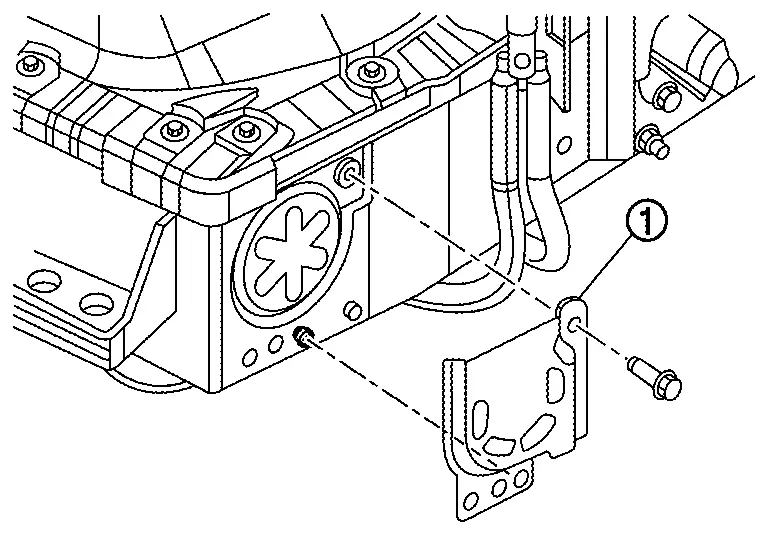
Remove bracket .
|
: Bolts |
WARNING:
To prevent electric shock, wear insulated protective gear and use insulated tools.
Remove bolts and then remove busbar 5.
WARNING:
To prevent electric shock, wear insulated protective gear and use insulated tools.
NOTE:
The figure shows busbar 5.
Remove busbar 20 in the same way.
Assembly
Note the following items, and assemble in the reverse order of disassembly.
DANGER:-
There is the danger of electric shock caused by contact with the terminals. Be sure to wear insulated protective gear and use insulated tools.
-
Because there is a danger of electric shock and fire, never allow bus bar to contact a wrong terminal.
-
If bus bar contacts a wrong terminal, the circuit becomes energized and a short may occur.
-
Always keep the bus bar cover closed until immediately before the installation of bus bar.
-
busbar 6, busbar 7, busbar 18 and busbar 19
DISASSEMBLY
Remove the battery upper floor assembly. Refer to Disassembly & Assembly.
Remove bolt and nut. And then remove busbar 7.
WARNING:
To prevent electric shock, wear insulated protective gear and use insulated tools.
Remove the bolt . And then remove busbar 6 .
WARNING:
To prevent electric shock, wear insulated protective gear and use insulated tools.
Remove other busbar in the same way.
Assembly
Note the following items, and assemble in the reverse order of disassembly.
DANGER:-
There is the danger of electric shock caused by contact with the terminals. Be sure to wear insulated protective gear and use insulated tools.
-
Because there is a danger of electric shock and fire, never allow bus bar to contact a wrong terminal.
-
If bus bar contacts a wrong terminal, the circuit becomes energized and a short may occur.
-
Always keep the bus bar cover closed until immediately before the installation of bus bar.
-
busbar 8 and busbar 17
DISASSEMBLY
Remove the battery upper floor assembly. Refer to Disassembly & Assembly.
Remove the bolt . And then busbar 8 .
WARNING:
To prevent electric shock, wear insulated protective gear and use insulated tools.
Remove busbar 17 in the same way.
Assembly
Note the following items, and assemble in the reverse order of disassembly.
DANGER:-
There is the danger of electric shock caused by contact with the terminals. Be sure to wear insulated protective gear and use insulated tools.
-
Because there is a danger of electric shock and fire, never allow bus bar to contact a wrong terminal.
-
If bus bar contacts a wrong terminal, the circuit becomes energized and a short may occur.
-
Always keep the bus bar cover closed until immediately before the installation of bus bar.
-
busbar 9
DISASSEMBLY
Remove the battery upper floor assembly. Refer to Disassembly & Assembly.
Remove busbar 8 and busbar 17.
Remove the bracket bolt and . And then move the harness to keep the work space.
Remove the bolt. And then busbar 9.
WARNING:
To prevent electric shock, wear insulated protective gear and use insulated tools.
Assembly
Note the following items, and assemble in the reverse order of disassembly.
DANGER:-
There is the danger of electric shock caused by contact with the terminals. Be sure to wear insulated protective gear and use insulated tools.
-
Because there is a danger of electric shock and fire, never allow bus bar to contact a wrong terminal.
-
If bus bar contacts a wrong terminal, the circuit becomes energized and a short may occur.
-
Always keep the bus bar cover closed until immediately before the installation of bus bar.
-
busbar 10 and busbar 16
DISASSEMBLY
Remove service plug bracket. Refer to Disassembly & Assembly.
Remove the bolt and nut. And then remove busbar 10.
WARNING:
To prevent electric shock, wear insulated protective gear and use insulated tools.
Remove busbar 16 in the same way.
Assembly
Note the following items, and assemble in the reverse order of disassembly.
DANGER:-
There is the danger of electric shock caused by contact with the terminals. Be sure to wear insulated protective gear and use insulated tools.
-
Because there is a danger of electric shock and fire, never allow bus bar to contact a wrong terminal.
-
If bus bar contacts a wrong terminal, the circuit becomes energized and a short may occur.
-
Always keep the bus bar cover closed until immediately before the installation of bus bar.
-
busbar 11 and busbar 15
DISASSEMBLY
Remove the bolt . And then busbar 11 .
WARNING:
To prevent electric shock, wear insulated protective gear and use insulated tools.
NOTE:
The figure shows busbar 11.
Remove busbar 15 in the same way.
Assembly
Note the following items, and assemble in the reverse order of disassembly.
DANGER:-
There is the danger of electric shock caused by contact with the terminals. Be sure to wear insulated protective gear and use insulated tools.
-
Because there is a danger of electric shock and fire, never allow bus bar to contact a wrong terminal.
-
If bus bar contacts a wrong terminal, the circuit becomes energized and a short may occur.
-
Always keep the bus bar cover closed until immediately before the installation of bus bar.
-
Battery Junction Box and Battery Harness Nissan Ariya: FE0
Exploded View
BATTERY JUNCTION BOX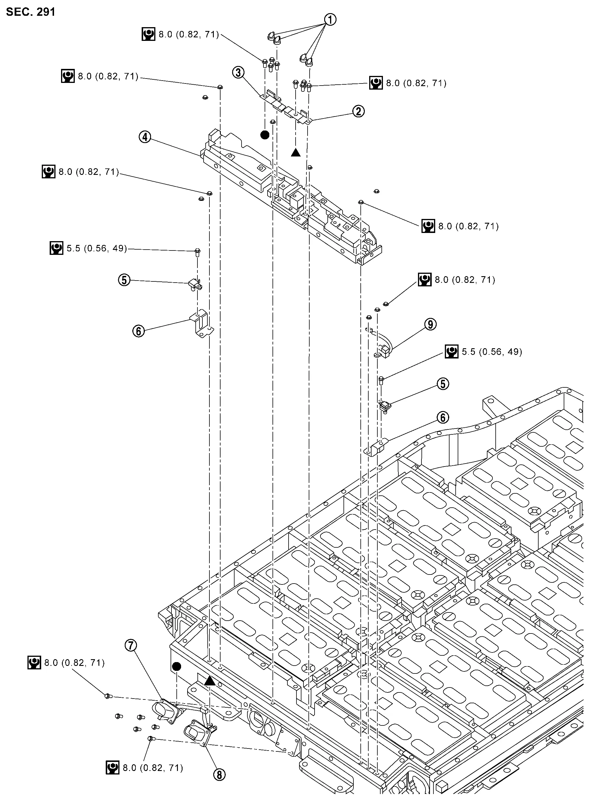
|
Nut cap | |
Busbar 1 | |
Busbar 20 |
|
Battery junction box | |
Battery pack pressure sensor | |
Bracket |
|
High-voltage harness connector | |
High-voltage harness connector | |
Battery pack water temperature sensor |
|
: N·m (kg-m, in-lb) | ||||
| ,: Indicates that the part is connected at points with same symbol in actual Nissan Ariya vehicle. |
|||||
BATTERY HARNESS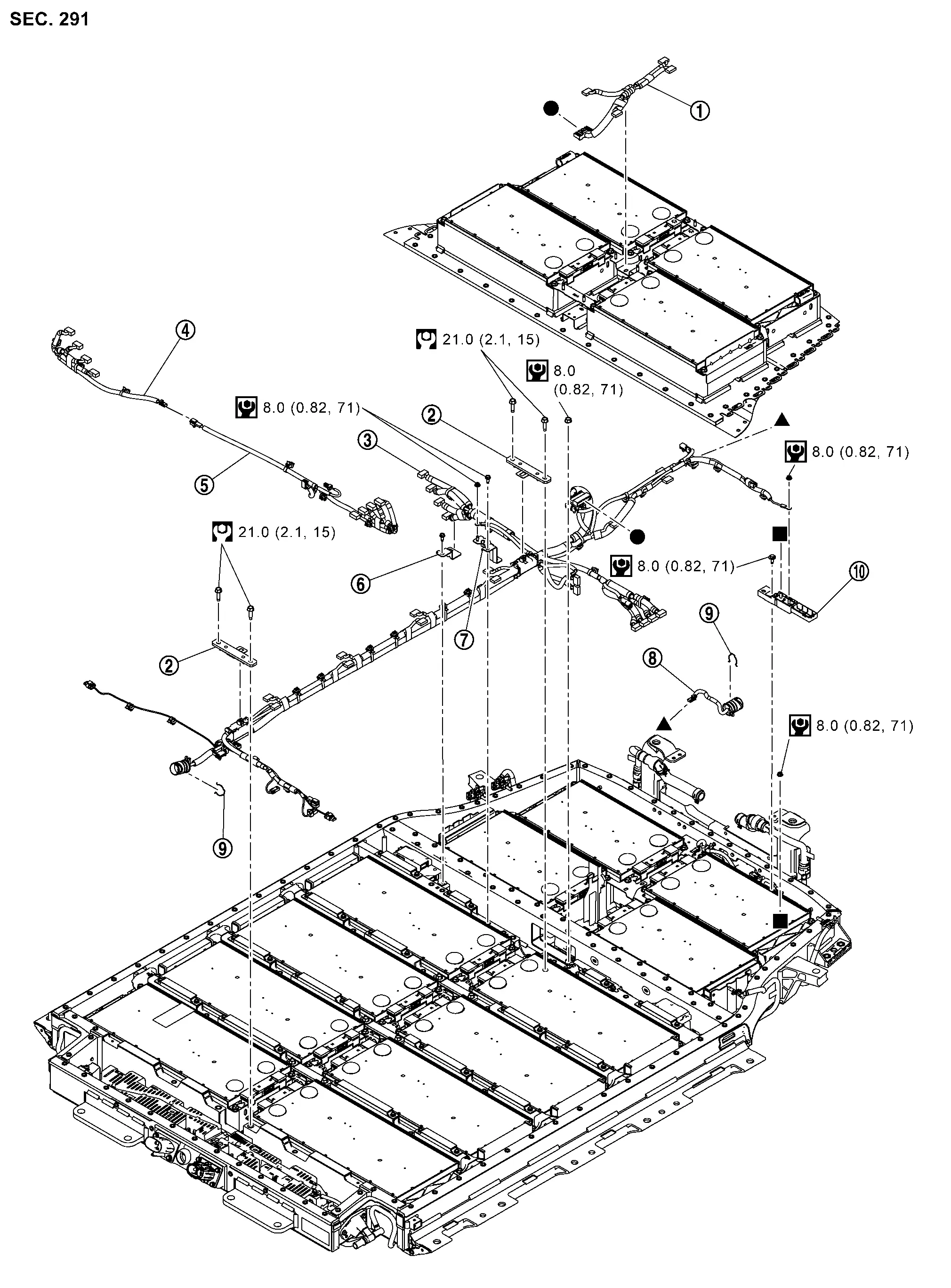
|
Nissan Ariya Vehicle communication harness | |
Bracket | |
Nissan Ariya Vehicle communication harness |
|
Cell voltage detection harness | |
Cell voltage detection harness | |
Bracket |
|
Bracket | |
Nissan Ariya Vehicle communication harness (battery PTC) | |
Clip |
|
Busbar terminal block | ||||
|
: N·m (kg-m, in-lb) | ||||
|
: N·m (kg-m, ft-lb) | ||||
| ,, : Indicates that the part is connected at points with same symbol in actual Nissan Ariya vehicle. |
|||||
Disassembly & Assembly
DANGER:Because hybrid vehicles and electric vehicles contain a high voltage battery, there is a risk of electric shock, electric leakage, or similar accidents if the Nissan Ariya vehicle is handled incorrectly. Be sure to follow the correct work procedures when performing inspection and maintenance.
WARNING:
-
Be sure to remove the service plug in order to shut off the high voltage circuits before performing inspection or maintenance of high voltage system harnesses and parts.
-
Be sure to put the removed service plug in pocket and carry it or store it in a tool box or other container so that another person does not accidentally connect it while work is in progress.
-
Be sure to put on insulating protective gear before beginning work on the high voltage system.
-
Clearly identify the persons responsible for high voltage work and ensure that other persons do not touch the Nissan Ariya vehicle. When not working, cover high voltage components with an anti-static cover sheet or similar item to prevent contact with other persons.
-
Refer to PRECAUTIONS FOR HIGH VOLTAGE : Precautions.
-
If the battery pack is to be disassembled, be sure to remove the Li-ion battery controller for preventing electric shock, fire, and damage to parts.
CAUTION:
There is the possibility of a malfunction occurring if the vehicle is changed to READY status while the service plug is removed. Therefore do not change the Nissan Ariya vehicle to READY status unless instructed to do so in the Service Manual.
ENVIRONMENT FOR LI-ION BATTERY DISASSEMBLY WORK
Must be an indoor environment.
-
The environment must utilize a shutter or other means to shut out the outside environment and prevent rain, snow, dust, or other substances from entering.
-
The environment must not cause the intrusion of sweat during work, or cause condensation to occur due to high temperature or humidity.
Metal powder, grease, and other foreign substances must not enter.
-
The indoor environment must also prevent metal powder, grease, and other foreign substances from entering due to maintenance performed on other Nissan Ariya vehicles and other sources during disassembly work.
-
During disassembly without internal work, temporarily close the battery pack upper case or cover it with an insulating cover.
The floor must be dry.
-
The floor must not be wet as a result of factors such as Nissan Ariya vehicle entry during rain or snow.
Work space
-
The work space must be approximately the size of one entire Nissan Ariya vehicle.
-
Take appropriate countermeasures so that persons other than the operator do not enter the work space, such as by placing signs indicating that disassembly work is in progress.
Standard fire fighting equipment
-
Always place a standard fire fighting equipment in the disassembly work area.
-
Depending on type of fire (Nissan Ariya vehicle or battery) use standard fire fighting equipment (water or extinguisher).
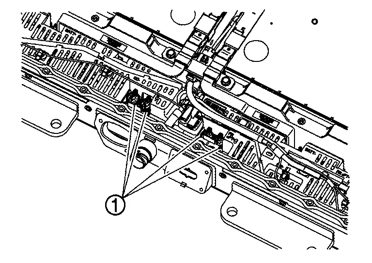
VEHICLE COMMUNICATION HARNESS
DISASSEMBLY
Remove service plug bracket assembly. Refer to Disassembly & Assembly.
Remove battery upper floor assembly. Refer to Disassembly & Assembly.
Remove each busbar. Refer to Disassembly & Assembly.
Remove battery junction box.
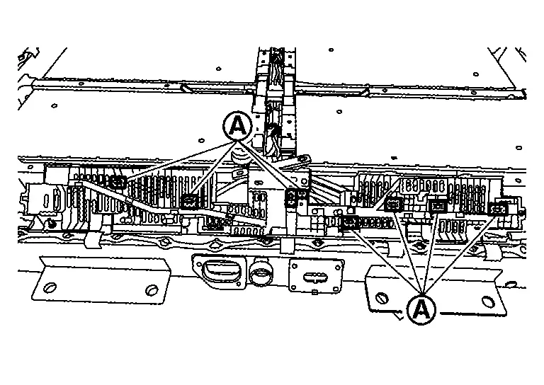
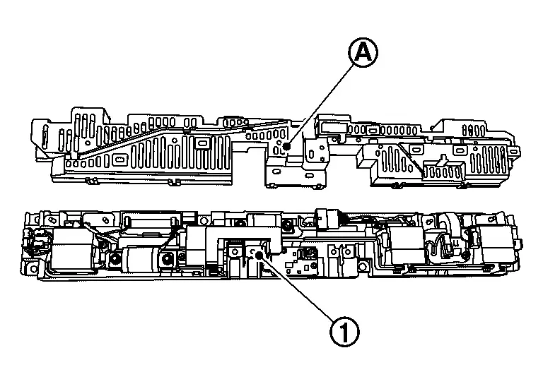
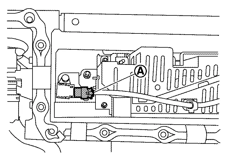
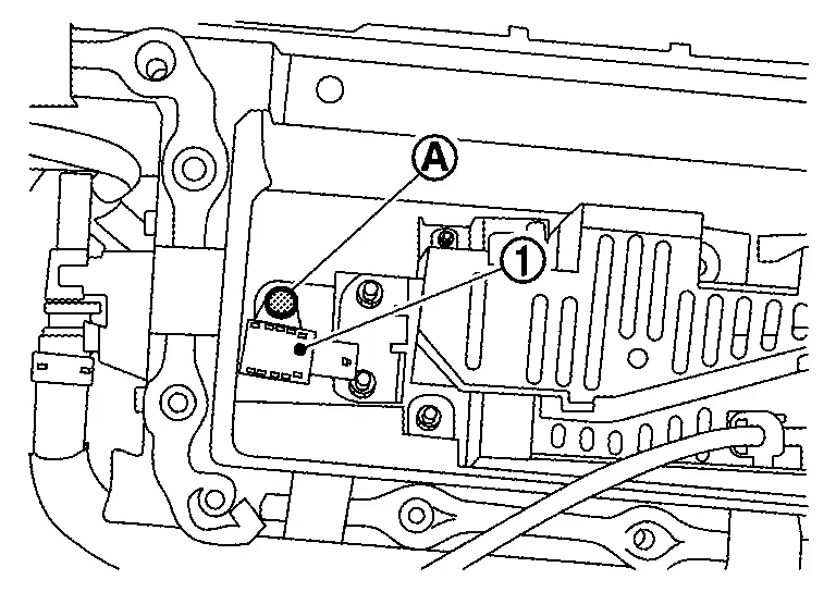
Remove harness connector from module.
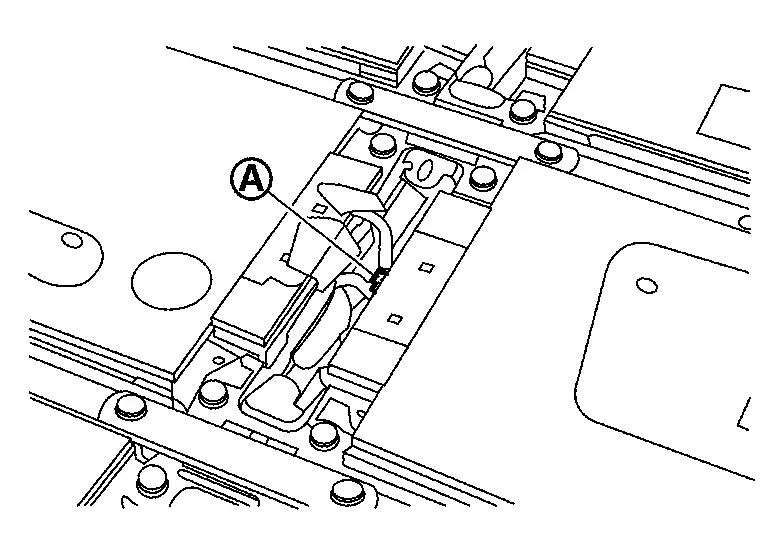
WARNING:
To prevent electric shock, wear insulated protective gear.
CAUTION:
Because there is the danger of electric shock, immediately insulate removed connector with insulating tape.
NOTE:
-
Remove from each module.
-
Harness connector lock is located on the bottom.
Remove bolts and then remove brackets.
WARNING:
To prevent electric shock, wear insulated protective gear and use insulated tools.
Remove bolts .
WARNING:
To prevent electric shock, wear insulated protective gear and use insulated tools.
Open busbar terminal table and then remove nut .
WARNING:
To prevent electric shock, wear insulated protective gear and use insulated tools.
Remove connectors , and .
WARNING:
To prevent electric shock, wear insulated protective gear.
CAUTION:
Because there is the danger of electric shock, immediately insulate removed connector with insulating tape.
Remove Nissan Ariya vehicle communication harness from battery pack lower case.
WARNING:
To prevent electric shock, wear insulated protective gear.
If necessary, Remove bracket from Nissan Ariya vehicle communication harness.
ASSEMBLY
Note the following items, and assemble in the reverse order of disassembly.
DANGER:-
There is the danger of electric shock caused by contact with the terminals. Be sure to wear insulated protective gear and use insulated tools.
-
Because there is a danger of electric shock and fire, never allow bus bar to contact a wrong terminal.
-
If bus bar contacts a wrong terminal, the circuit becomes energized and a short may occur.
-
Always keep the bus bar cover closed until immediately before the installation of bus bar.
-
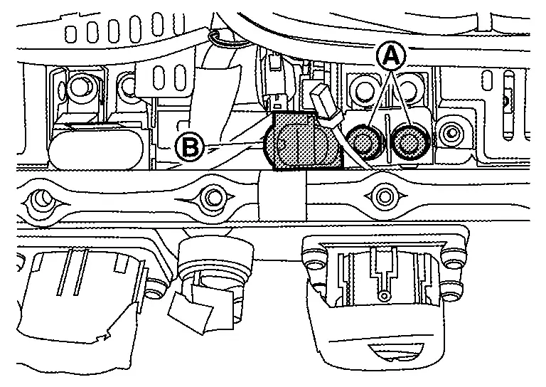
HIGH-VOLTAGE HARNESS CONNECTOR
DISASSEMBLY
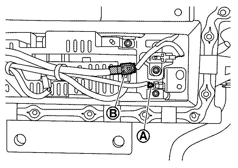
Remove interlock detecting harness connector .
WARNING:
To prevent electric shock, wear insulated protective gear.
CAUTION:
Because there is the danger of electric shock, immediately insulate removed connector with insulating tape.
Open cap and then remove bolt .
WARNING:
To prevent electric shock, wear insulated protective gear and use insulated tools.
Remove bolts and then remove high-voltage harness connector .
WARNING:
To prevent electric shock, wear insulated protective gear and use insulated tools.
Remove another high-voltage harness connector in the same way.
NOTE:
Busbar 20 has two claws on a cap.
Assembly.
Note the following items, and assemble in the reverse order of disassembly.
DANGER:-
There is the danger of electric shock caused by contact with the terminals. Be sure to wear insulated protective gear and use insulated tools.
-
Because there is a danger of electric shock and fire, never allow bus bar to contact a wrong terminal.
-
If bus bar contacts a wrong terminal, the circuit becomes energized and a short may occur.
-
Always keep the bus bar cover closed until immediately before the installation of bus bar.
-
BUABAR 1 AND BUSBAR 24
DISASSEMBLY
Remove high-voltage harness connector.
Remove nut cap
WARNING:
To prevent electric shock, wear insulated protective gear and use insulated tools.
Remove bolt and then remove busbar 1 .
WARNING:
To prevent electric shock, wear insulated protective gear and use insulated tools.
Remove busbar 24 in the same way.
Assembly.
Note the following items, and assemble in the reverse order of disassembly.
DANGER:-
There is the danger of electric shock caused by contact with the terminals. Be sure to wear insulated protective gear and use insulated tools.
-
Because there is a danger of electric shock and fire, never allow bus bar to contact a wrong terminal.
-
If bus bar contacts a wrong terminal, the circuit becomes energized and a short may occur.
-
Always keep the bus bar cover closed until immediately before the installation of bus bar.
-
BATTERY JUNCTION BOX
DISASSEMBLY
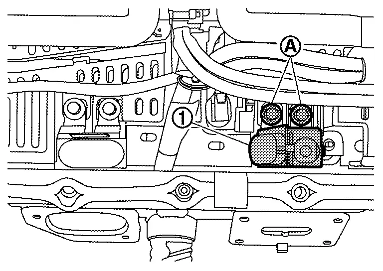
Remove high-voltage harness connector.
Remove busbar 1 and busbar 24.
Remove busbar 2 and busbar 23. Refer to Disassembly & Assembly.
Remove busbar 41 and busbar 47. Refer to Disassembly & Assembly.
Remove clip and then push Nissan Ariya vehicle communication harness connector in the battery pack lower case.
WARNING:
To prevent electric shock, wear insulated protective gear and use insulated tools.
CAUTION:
Because there is the danger of electric shock, immediately insulate removed connector with insulating tape.
Remove bolts .
WARNING:
To prevent electric shock, wear insulated protective gear and use insulated tools.
Remove harness connector of battery pack pressure sensor and harness connector of battery pack water temperature sensor.
WARNING:
To prevent electric shock, wear insulated protective gear.
CAUTION:
Because there is the danger of electric shock, immediately insulate removed connector with insulating tape.
Remove harness connector of battery pack pressure sensor.
WARNING:
To prevent electric shock, wear insulated protective gear.
CAUTION:
Because there is the danger of electric shock, immediately insulate removed connector with insulating tape.
Remove connector harness of Nissan Ariya vehicle communication harness.
WARNING:
To prevent electric shock, wear insulated protective gear.
CAUTION:
Because there is the danger of electric shock, immediately insulate removed connector with insulating tape.
Remove nuts of battery junction box.
WARNING:
To prevent electric shock, wear insulated protective gear and use insulated tools.
Lift battery junction box and release claws on upper cover of battery junction box.
WARNING:
To prevent electric shock, wear insulated protective gear and use insulated tools.
Remove harness clips from battery junction box.
WARNING:
To prevent electric shock, wear insulated protective gear and use insulated tools.
Assembly
Note the following items, and assemble in the reverse order of disassembly.
DANGER:-
There is the danger of electric shock caused by contact with the terminals. Be sure to wear insulated protective gear and use insulated tools.
-
Because there is a danger of electric shock and fire, never allow bus bar to contact a wrong terminal.
-
If bus bar contacts a wrong terminal, the circuit becomes energized and a short may occur.
-
Always keep the bus bar cover closed until immediately before the installation of bus bar.
-
Install upper cover to battery junction box .
Install battery junction box to battery pack lower case.
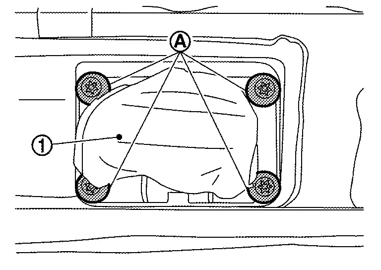
BATTERY PACK PRESSURE SENSOR
DISASSEMBLY
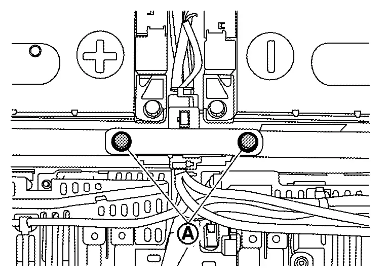
Remove harness connector of battery pack pressure sensor.
WARNING:
To prevent electric shock, wear insulated protective gear.
CAUTION:
Because there is the danger of electric shock, immediately insulate removed connector with insulating tape.
Remove bolt and then remove battery pack pressure sensor .
WARNING:
To prevent electric shock, wear insulated protective gear and use insulated tools.
Remove left battery pack pressure sensor in the same way.
ASSEMBLY
Note the following items, and assemble in the reverse order of disassembly.
DANGER:-
There is the danger of electric shock caused by contact with the terminals. Be sure to wear insulated protective gear and use insulated tools.
-
Because there is a danger of electric shock and fire, never allow bus bar to contact a wrong terminal.
-
If bus bar contacts a wrong terminal, the circuit becomes energized and a short may occur.
-
Always keep the bus bar cover closed until immediately before the installation of bus bar.
-
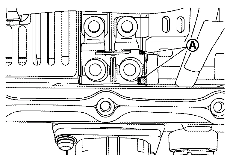
BATTERY PACK WATER TEMPERATURE SENSOR
DISASSEMBLY
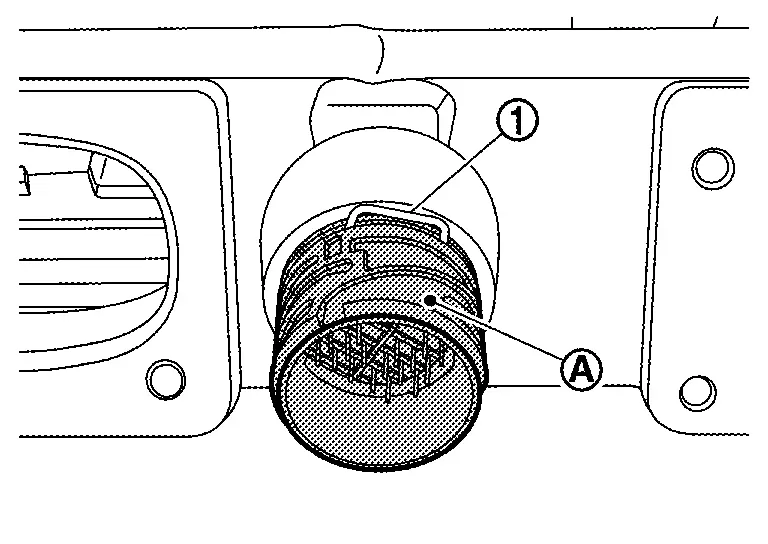
Disconnect harness connector of battery pack water temperature sensor and battery pack pressure sensor.
WARNING:
To prevent electric shock, wear insulated protective gear.
CAUTION:
Because there is the danger of electric shock, immediately insulate removed connector with insulating tape.
Remove nut and then remove battery pack pressure sensor .
WARNING:
To prevent electric shock, wear insulated protective gear and use insulated tools.
NOTE:
The figure shows the state that battery pack pressure sensor is removed.
ASSEMBLY
Note the following items, and assemble in the reverse order of disassembly.
DANGER:-
There is the danger of electric shock caused by contact with the terminals. Be sure to wear insulated protective gear and use insulated tools.
-
Because there is a danger of electric shock and fire, never allow bus bar to contact a wrong terminal.
-
If bus bar contacts a wrong terminal, the circuit becomes energized and a short may occur.
-
Always keep the bus bar cover closed until immediately before the installation of bus bar.
-
Front Module Stack Nissan Ariya 2023
Exploded View
|
Bracket | |
Bracket | |
Bracket |
|
Module No.16 (MD16) | |
Module No.15 (MD15) | |
Module No.14 (MD14) |
|
Module No.13 (MD13) | |
Bracket | |
Module No.4 (MD4) |
|
Module No.3 (MD3) | |
Module No.2 (MD2) | |
Module No.1 (MD1) |
|
: Comply with the assembly procedure when installing. Disassembly & Assembly | ||||
|
: N·m (kg-m, ft-lb) | ||||
| ,,: Indicates that the part is connected at points with same symbol in actual Nissan Ariya vehicle. |
|||||
Disassembly & Assembly
DANGER: Since hybrid vehicles and electric vehicles contain a high voltage battery, there is the risk of electric shock, electric leakage, or similar accidents if the high voltage component and Nissan Ariya vehicle are handled incorrectly. Be sure to follow the correct work procedures when performing inspection and maintenance.
WARNING:
-
Be sure to remove the service plug in order to shut off the high voltage circuits before performing inspection or maintenance of high voltage system harnesses and parts.
-
Be sure to put the removed service plug in pocket and carry it or store it in a tool box or other container so that another person does not accidentally connect it while work is in progress.
-
Be sure to put on insulating protective gear before beginning work on the high voltage system.
-
Clearly identify the persons responsible for high voltage work and ensure that other persons do not touch the Nissan Ariya vehicle. When not working, cover high voltage components with an anti-static cover sheet or similar item to prevent contact with other persons. Refer to HIGH VOLTAGE PRECAUTIONS : Precautions.
-
If the battery pack is to be disassembled, be sure to remove the Li-ion battery controller for preventing electric shock, fire, and damage to parts.
CAUTION:
There is the possibility of a malfunction occurring if the vehicle is changed to READY status while the service plug is removed. Therefore do not change the Nissan Ariya vehicle to READY status unless instructed to do so in the Service Manual.
ENVIRONMENT FOR LI-ION BATTERY DISASSEMBLY WORK
Must be an indoor environment.
-
The environment must utilize a shutter or other means to shut out the outside environment and prevent rain, snow, dust, or other substances from entering.
-
The environment must not cause the intrusion of sweat during work, or cause condensation to occur due to high temperature or humidity.
Metal powder, grease, and other foreign substances must not enter.
-
The indoor environment must also prevent metal powder, grease, and other foreign substances from entering due to maintenance performed on other Nissan Ariya vehicles and other sources during disassembly work.
-
During disassembly without internal work, temporarily close the battery pack upper case or cover it with an insulating cover.
The floor must be dry.
-
The floor must not be wet as a result of factors such as Nissan Ariya vehicle entry during rain or snow.
Work space
-
The work space must be approximately the size of one entire Nissan Ariya vehicle.
-
Take appropriate countermeasures so that persons other than the operator do not enter the work space, such as by placing signs indicating that disassembly work is in progress.
Standard fire fighting equipment
-
Always place a standard fire fighting equipment in the disassembly work area.
-
Depending on type of fire (Nissan Ariya vehicle or battery) use standard fire fighting equipment (water or extinguisher).
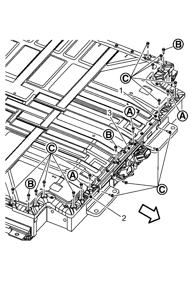
DISASSEMBLY
Remove battery upper case rear. [module No. 4 (MD4) and module No. 13 (MD13) only] Refer to Removal & Installation.
Remove battery upper floor assembly with module. [module No. 4 (MD4) and module No. 13 (MD13) only] Refer to Disassembly & Assembly.
Remove each busbar. Refer to Disassembly & Assembly.
Remove harness connector from module.
WARNING:
To prevent electric shock, wear insulated protective gear.
CAUTION:
Because there is the danger of electric shock, immediately insulate removed connector with insulating tape.
NOTE:
Lock of harness connector is located lower side.
Remove bolt and then remove bracket .
WARNING:
To prevent electric shock, wear insulated protective gear and use insulated tools.
NOTE:
The bracket is located beside the module.
Remove bracket bolts that contact to the module to be removed.
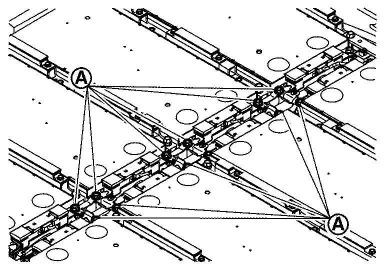
WARNING:
To prevent electric shock, wear insulated protective gear and use insulated tools.
Remove bolt and then remove bracket .
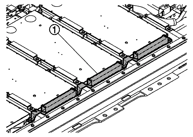
WARNING:
To prevent electric shock, wear insulated protective gear and use insulated tools.
NOTE:
-
The figure shows left bracket.
-
When removing module 13 (MD13) from module 16 (MD16), remove right bracket.
Remove bolt . [module No.1 (MD1) or module No.16 (MD116) only]
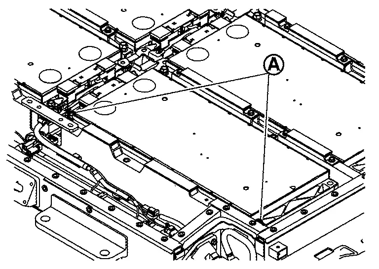
WARNING:
To prevent electric shock, wear insulated protective gear and use insulated tools.
NOTE:
The figure shows module No.1 (MD1).
Remove bolt . [module No.4 (MD4) or module No.13 (MD13) only]
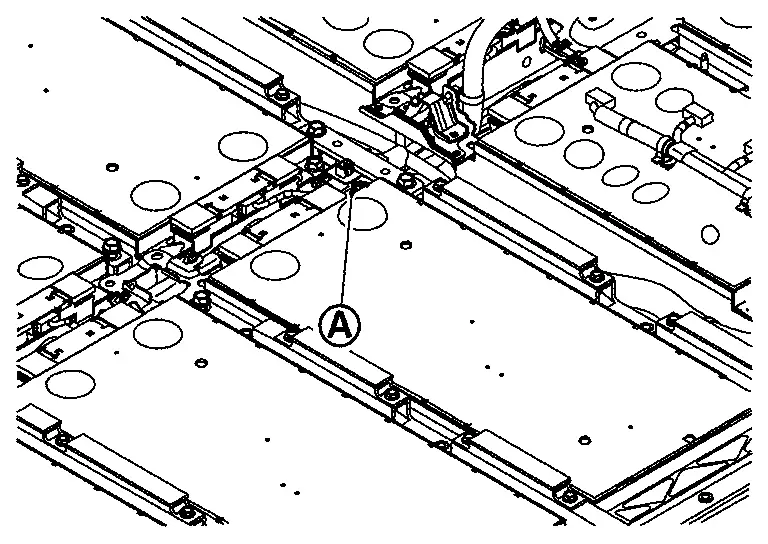
WARNING:
To prevent electric shock, wear insulated protective gear and use insulated tools.
NOTE:
The figure shows module No.4 (MD4).
Hang carabiners (service part: 299A3 5MP0A) in the lifting holes and install belt slinger.
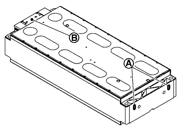
WARNING:
To prevent electric shock, wear insulated protective gear.
CAUTION:
Install carabiners in the lifting holes on the opposite side part of the terminal.
NOTE:
Carabiners (service part: 299A3 5MP0A) are packed with new module.
Install temporarily module mounting bolt to terminal side by screwing several rotations.
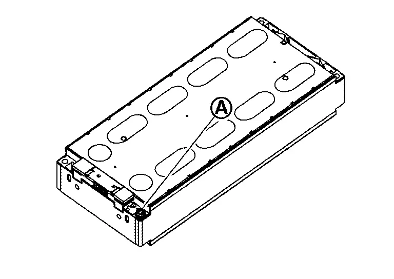
WARNING:
To prevent electric shock, wear insulated protective gear.
NOTE:
-
To prevent movement when removing the module.
-
Leave a gap between the bolt head and the module.
Lifting load is applied to the module using the mobile floor crane (A).
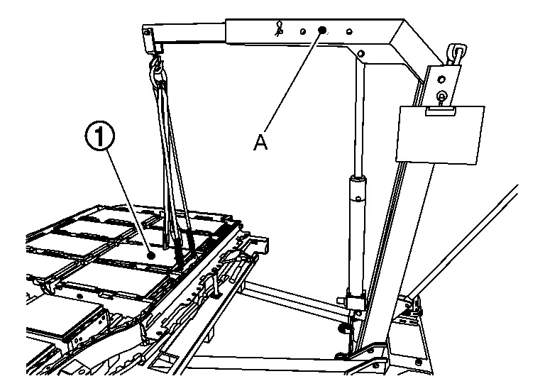
WARNING:
To prevent electric shock, wear insulated protective gear.
CAUTION:
-
If too much load is applied, the shock when it comes off is large. so carefully apply the load.
-
Battery pack is not lifted up by the load.
NOTE:
-
lifting load must be within 100 kgf approximately.
-
The figure shows module No. 14 (MD14).
Drive resin scraper (service parts: 299A3 5MP0A) (A) in gap filler with a resin hammer and pry left and right to peel the adhesion of gap filler.
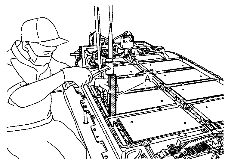
WARNING:
-
To prevent electric shock, wear insulated protective gear and use insulated tools.
-
Do not use metal bar, etc., it may cause electric shock, damage to floor surface due to battery pack, damage to module, and liquid leakage.
CAUTION:
-
Insert one with the thinner tip of resin scraper (service part: 299A3 5MP0A) (C) between the module end plate
and the cross member of battery pack lower case.
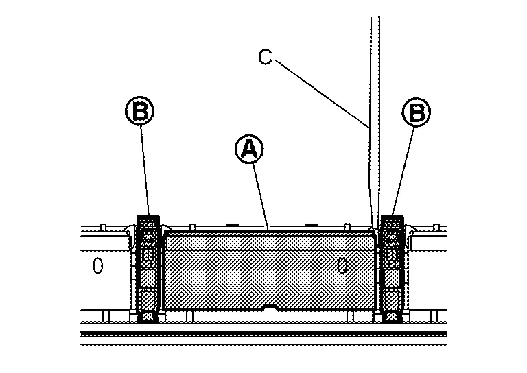
-
Never pry except module end plate
to prevent module from damaging, deforming and leaking liquid. -
Never remove 2 modules or more to prevent battery pack from weight unbalance except replacement work of battery pack lower case.
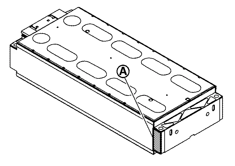
NOTE:
-
Modules are in close contact with gap filler applied to battery pack lower case.
-
It can be peeled off from gap filler by sliding module sideways.
-
Since adhesive strength of gap filler is weakened, the part that was peeled off once is not re-bonded.
Remove module that was temporarily installed to terminal side.
WARNING:
To prevent electric shock, wear insulated protective gear.
NOTE:
When module is lifted up, load the module on battery pack lower case by lowering mobile floor crane.
Hang carabiners (service part: 299A3 5MP0A) in the lifting holes and install belt slinger.
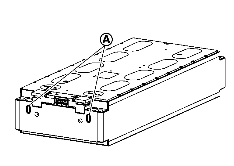
WARNING:
To prevent electric shock, wear insulated protective gear.
NOTE:
Carabiners (service part: 299A3 5MP0A) are packed with new module.
Remove module from battery lower case by lifting up 4 points of module with mobile floor crane.
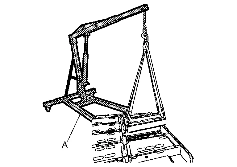
WARNING:
To prevent electric shock, wear insulated protective gear.
Peel off gap filler from battery pack lower case.
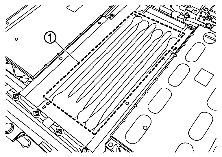
WARNING:
To prevent electric shock, wear insulated protective gear.
NOTE:
-
Gap filler can be peeled off with hands.
-
If it is not peeled off with hands, use resin scraper without damaging battery lower case.
ASSEMBLY
Note the following items, and assemble in the reverse order of disassembly.
DANGER:-
There is the danger of electric shock caused by contact with the terminals. Be sure to wear insulated protective gear and use insulated tools.
-
Because there is a danger of electric shock and fire, never allow bus bar to contact a wrong terminal.
-
If bus bar contacts a wrong terminal, the circuit becomes energized and a short may occur.
-
Always keep the bus bar cover closed until immediately before the installation of bus bar.
-
Check battery pack lower case inside for foreign material or peeled gap filler
Set gabari sheet to battery pack lower case as shown in the figure and then write lines on battery pack lower case with oil-based pen.
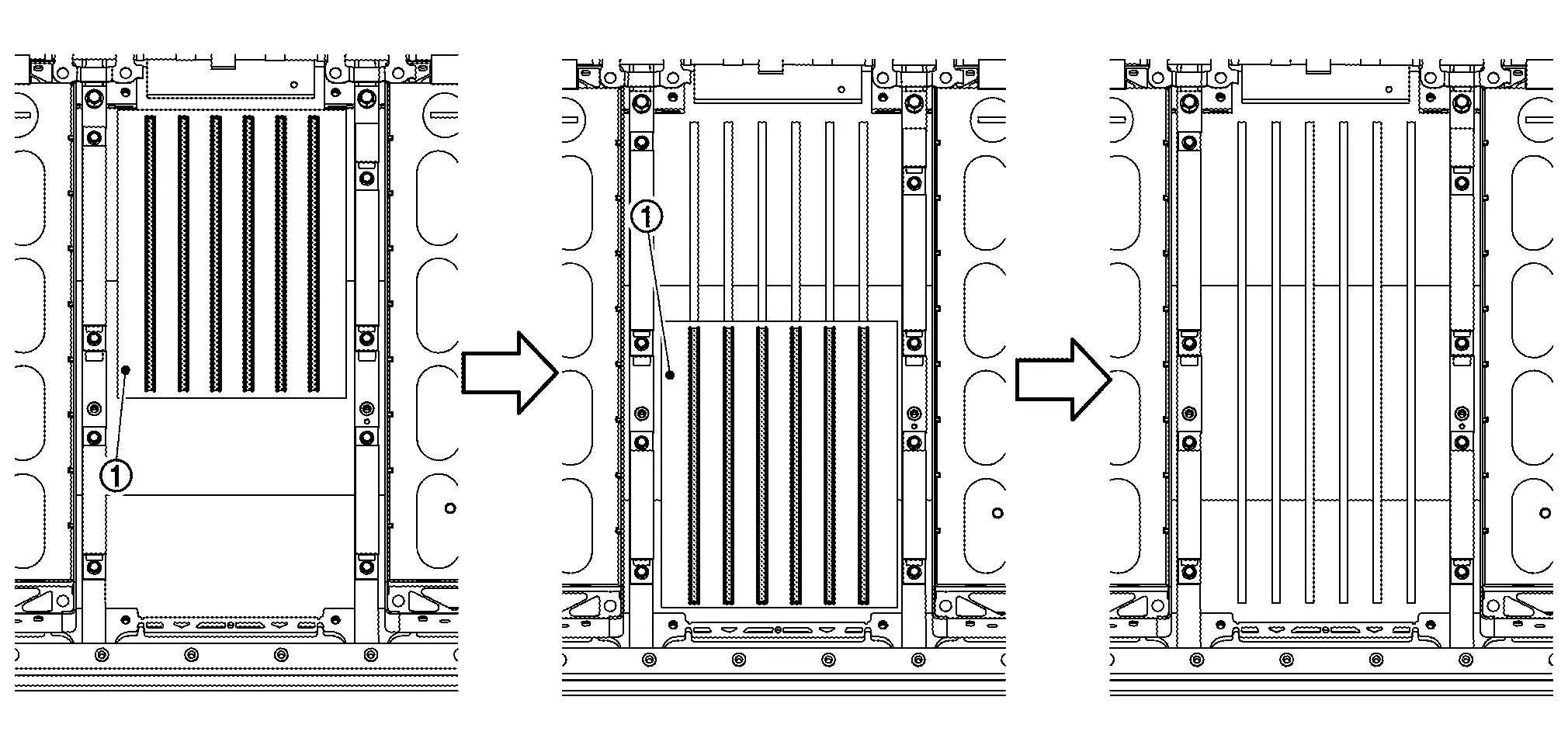
CAUTION:
-
Use a pen that does not have a thickness like paint.
-
Place gabari sheet in close contact with module mounting bracket and center it.
NOTE:
Size of gabari sheet is shown in the figure.
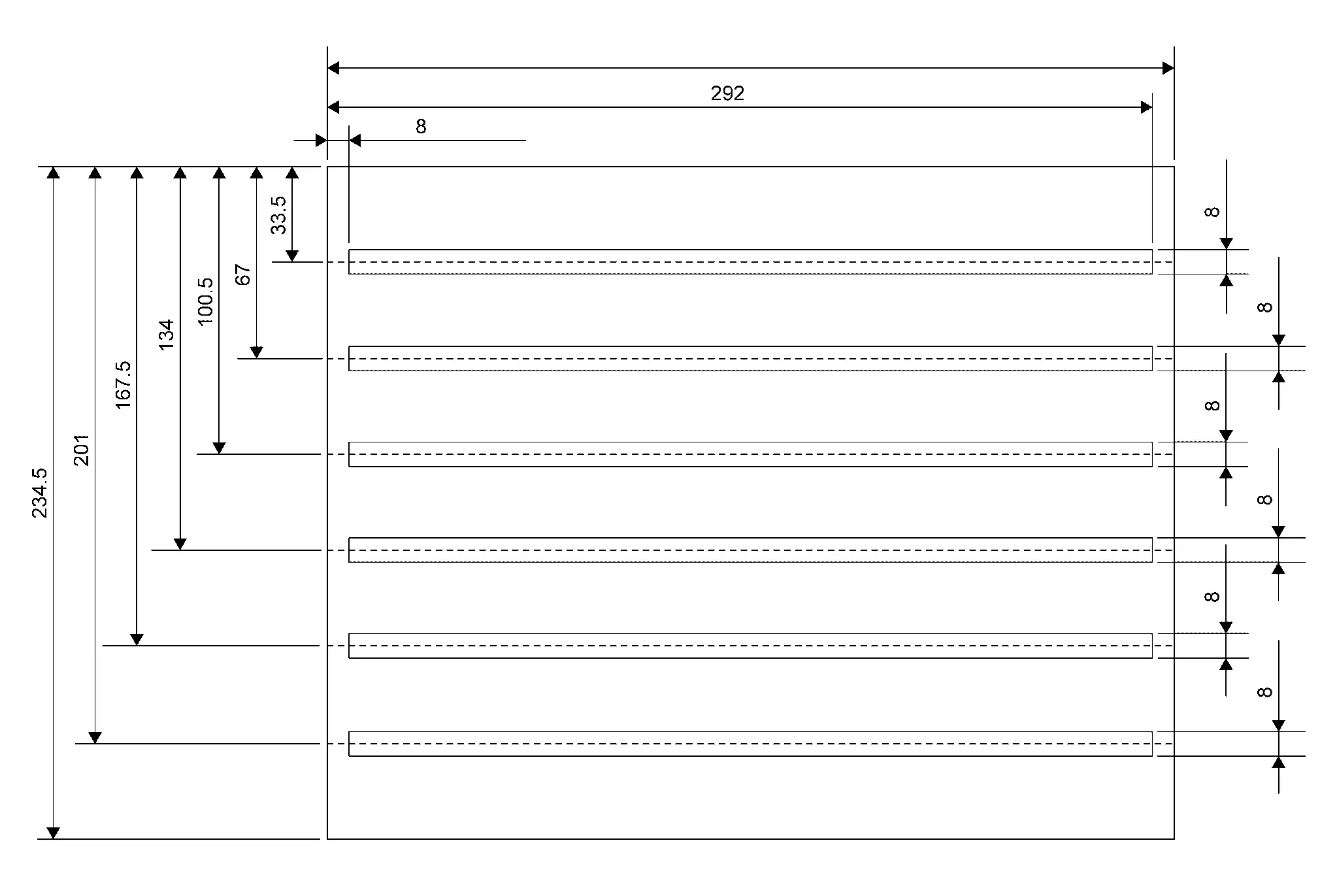
Cut the static mixer at the position shown in the figure.
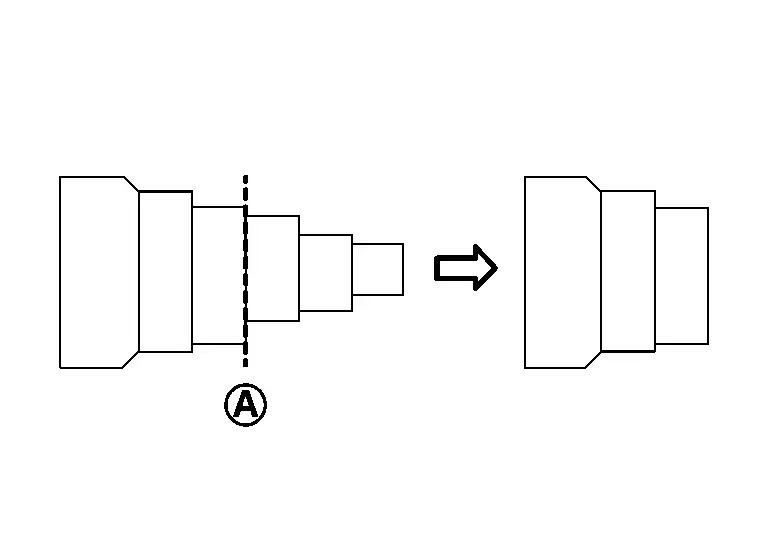
After taking out cartridge from packing box, check the followings;
-
No evidence of liquid leakage in the packing box.
-
No liquid leakage from bottom of cartridge
.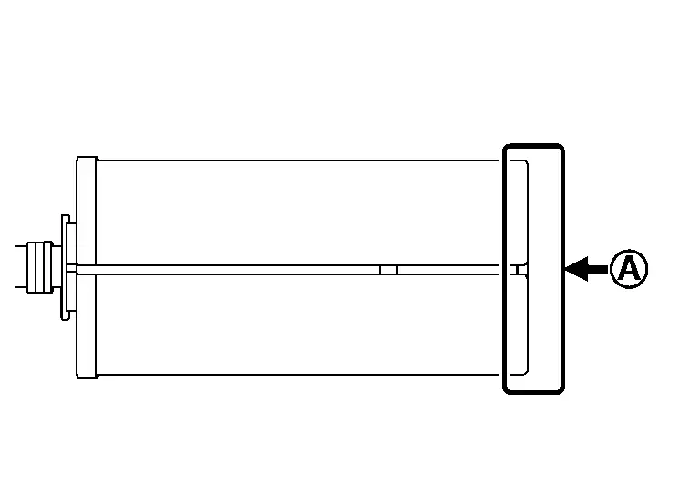
CAUTION:
-
If leakage is found, gap filler is separated. Prepare a replacement [Battery Gap Filler Kit (Service Part: B9522 5MP0A)] without using it.
-
Check carefully for leakage because liquid is colorless.
Set static mixer to cartridge.
Set cartridge to the gap filler gun [SST: BP2000400Z (J-53350)].
Attach guideline label to cartridge as shown in the figure.
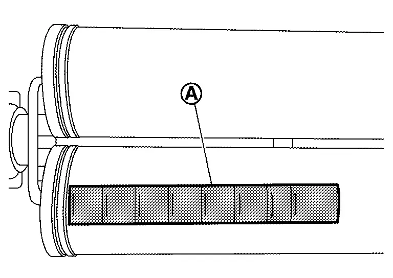
CAUTION:
Since guideline labels are depending on specification of battery and attached positions, select and attach specified one.
| Guideline label | : C-108 ml |
Apply gap filler in accordance with lines written on the battery pack lower case.
CAUTION:
-
Apply one row using one scale on cartridge. (If there is surplus, add it to a place with less amount.)
-
If gap filler
is applied thicker than the width of the lines, the amount will be short, so be careful. 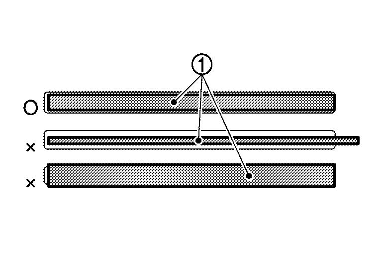
-
When applying gap filler, if the coating bead contains colorless liquid
, stop to use it because gap filler is separated and prepare a replacement [Battery Gap Filler Kit (service part: B9522 5MP0A)].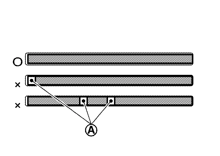
-
The process from the start of gap filler application to the completion of module installation (including tightening bolt ) must be within 1 hour.
NOTE:
One cartridge can be applied for just one module.
Install locate pin [SST: KV99119700 (J-53349)] to battery pack lower case.
Install module in the reverse order of removal.
NOTE:
When installing module mounting bolts, remove locate pin [SST: KV99119700 (J-53349)].
Rear Module Stack Nissan Ariya SUV
Exploded View
Rear module stack 2nd floor
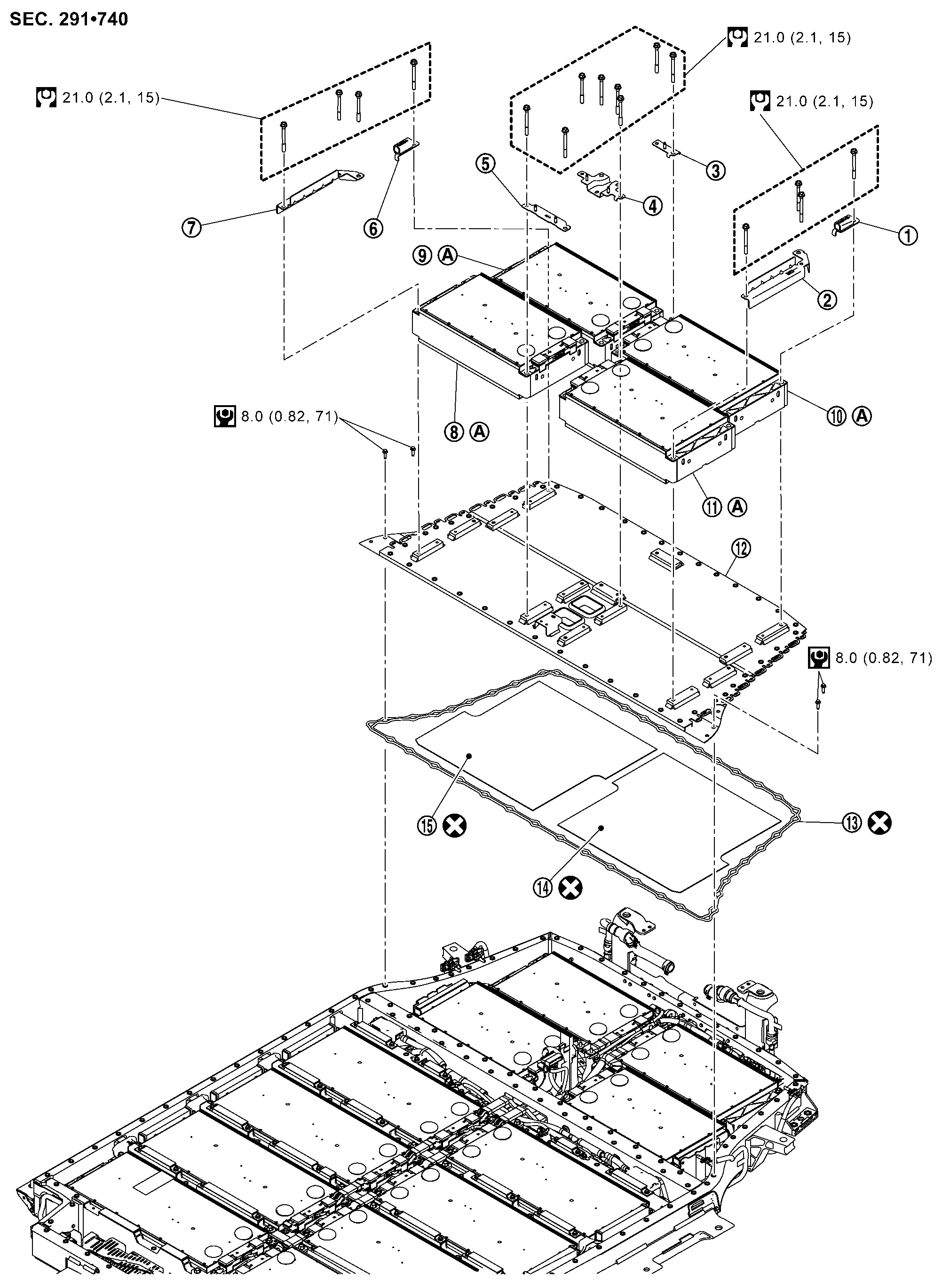
|
Bracket | |
Bracket | |
Bracket |
|
Bracket | |
Bracket | |
Bracket |
|
Bracket | |
Module No.10 (MD10) | |
Module No.9 (MD9) |
|
Module No.8 (MD8) | |
Module No.7 (MD7) | |
Battery upper floor assembly |
|
Seal | |
Heat shield sheet | |
Heat shield sheet |
|
: Comply with the assembly procedure when installing. Disassembly & Assembly | ||||
|
: Always replace after every disassembly. | ||||
|
: N·m (kg-m, in-lb) | ||||
|
: N·m (kg-m, ft-lb) | ||||
Rear module stack 1ST floor
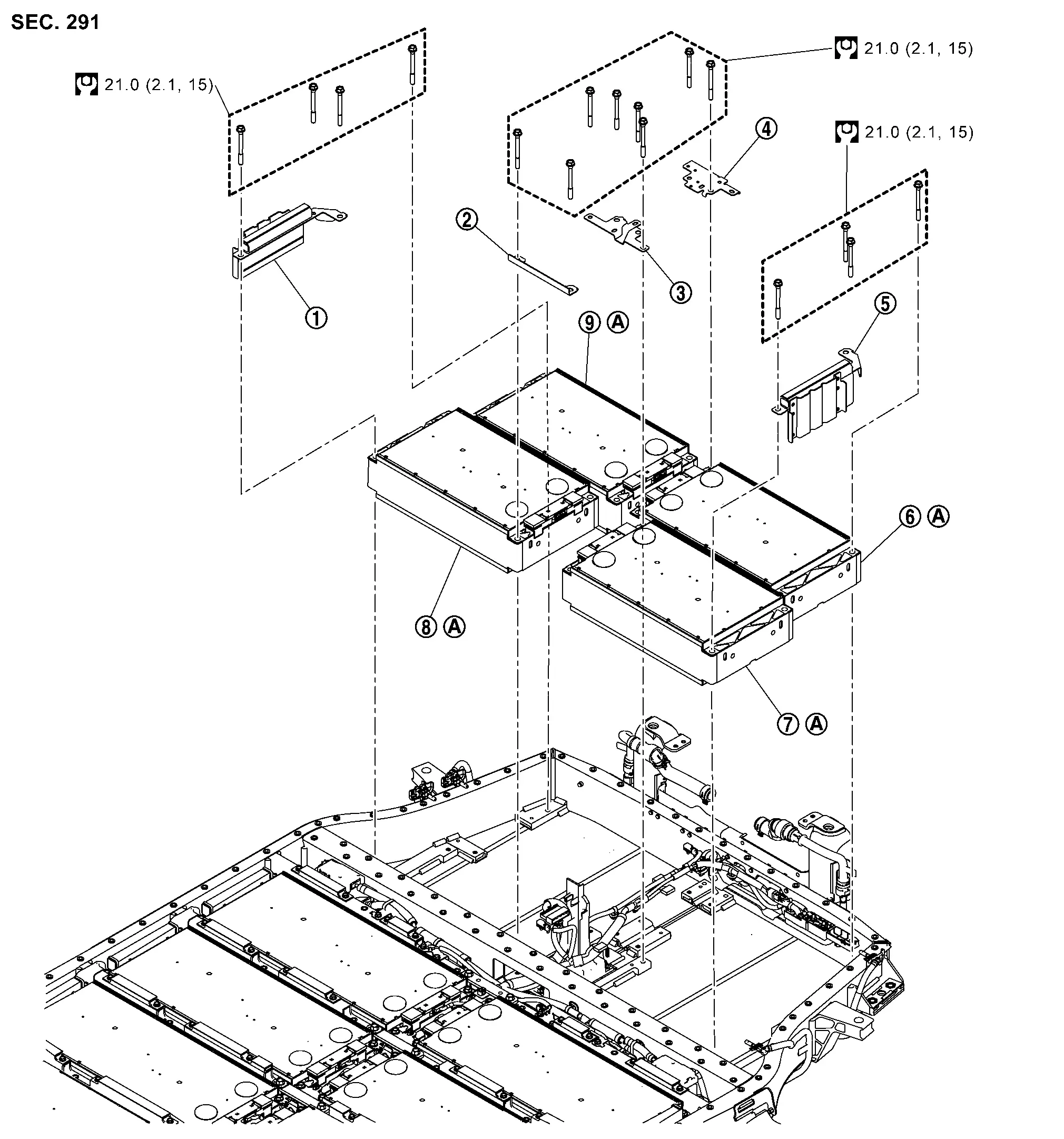
|
Bracket | |
Bracket | |
Bracket |
|
Bracket | |
Bracket | |
Module No.6 (MD6) |
|
Module No.5 (MD5) | |
Module No.12 (MD12) | |
Module No.11 (MD11) |
|
: Comply with the assembly procedure when installing. Disassembly & Assembly | ||||
|
: N·m (kg-m, in-lb) | ||||
|
: N·m (kg-m, ft-lb) | ||||
Disassembly & Assembly
DANGER: Since hybrid vehicles and electric vehicles contain a high voltage battery, there is the risk of electric shock, electric leakage, or similar accidents if the high voltage component and Nissan Ariya vehicle are handled incorrectly. Be sure to follow the correct work procedures when performing inspection and maintenance.
WARNING:
-
Be sure to remove the service plug in order to shut off the high voltage circuits before performing inspection or maintenance of high voltage system harnesses and parts.
-
Be sure to put the removed service plug in pocket and carry it or store it in a tool box or other container so that another person does not accidentally connect it while work is in progress.
-
Be sure to put on insulating protective gear before beginning work on the high voltage system.
-
Clearly identify the persons responsible for high voltage work and ensure that other persons do not touch the Nissan Ariya vehicle. When not working, cover high voltage components with an anti-static cover sheet or similar item to prevent contact with other persons. Refer to HIGH VOLTAGE PRECAUTIONS : Precautions.
-
If the battery pack is to be disassembled, be sure to remove the Li-ion battery controller for preventing electric shock, fire, and damage to parts.
CAUTION:
There is the possibility of a malfunction occurring if the vehicle is changed to READY status while the service plug is removed. Therefore do not change the Nissan Ariya vehicle to READY status unless instructed to do so in the Service Manual.
ENVIRONMENT FOR LI-ION BATTERY DISASSEMBLY WORK
Must be an indoor environment.
-
The environment must utilize a shutter or other means to shut out the outside environment and prevent rain, snow, dust, or other substances from entering.
-
The environment must not cause the intrusion of sweat during work, or cause condensation to occur due to high temperature or humidity.
Metal powder, grease, and other foreign substances must not enter.
-
The indoor environment must also prevent metal powder, grease, and other foreign substances from entering due to maintenance performed on other Nissan Ariya vehicles and other sources during disassembly work.
-
During disassembly without internal work, temporarily close the battery pack upper case or cover it with an insulating cover.
The floor must be dry.
-
The floor must not be wet as a result of factors such as Nissan Ariya vehicle entry during rain or snow.
Work space
-
The work space must be approximately the size of one entire Nissan Ariya vehicle.
-
Take appropriate countermeasures so that persons other than the operator do not enter the work space, such as by placing signs indicating that disassembly work is in progress.
Standard fire fighting equipment
-
Always place a standard fire fighting equipment in the disassembly work area.
-
Depending on type of fire (Nissan Ariya vehicle or battery) use standard fire fighting equipment (water or extinguisher).
BATTERY UPPER FLOOR ASSEMBLY (WITH MODULE)
DISASSEMBLY
Remove battery pack upper case rear. Refer to Removal & Installation.
Remove service plug bracket. Refer to Disassembly & Assembly.
Remove the cell voltage detection harness connector and the interlock detecting switch (service plug ) harness connector .
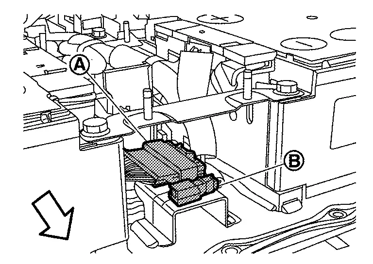
|
: Battery front |
WARNING:
To prevent electric shock, wear insulated protective gear.
CAUTION:
Because there is the danger of electric shock, immediately insulate removed connector with insulating tape.
Remove the bolt and bracket. And then temporary tighten the bolt .
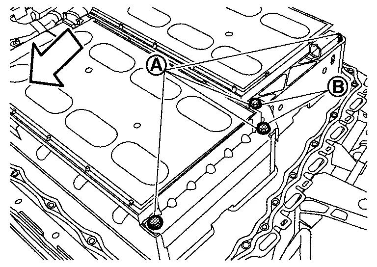
|
: Battery front |
WARNING:
To prevent electric shock, wear insulated protective gear and use insulated tools.
Open the busbar cover . And then remove the bolt and nut.
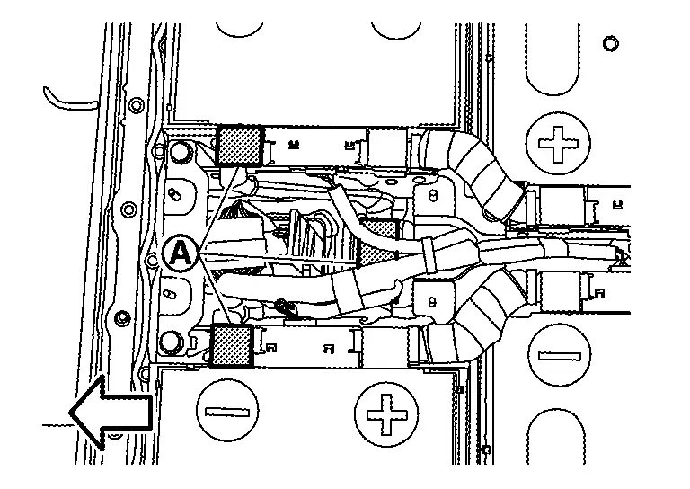
|
: Battery front |
WARNING:
To prevent electric shock, wear insulated protective gear and use insulated tools.
Remove busbar 10 and busbar 16.
install carabiners (service part: 299A3 5MP0A) (A) in the lifting holes and belt slinger (B) to the lifting holes.
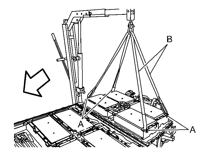
|
: Battery front |
WARNING:
To prevent electric shock, wear insulated protective gear.
NOTE:
Carabiners (service part: 299A3 5MP0A) are packed with new module.
Remove bolts. And then remove battery upper floor assembly with module using the mobile floor crane (engine crane).
WARNING:
To prevent electric shock, wear insulated protective gear and use insulated tools.
Remove the seal from battery pack lower case.
DISASSEMBLY
Check that heat shield sheet is still stuck back of battery upper floor assembly.
Install seal to battery upper floor assembly.
CAUTION:
The flat side of seal faces battery pack lower case.
WARNING:
To prevent electric shock, wear insulated protective gear.
Install guide pin [SST: KV99119600 (J-53348)] (A) to the center of battery pack upper floor assembly.
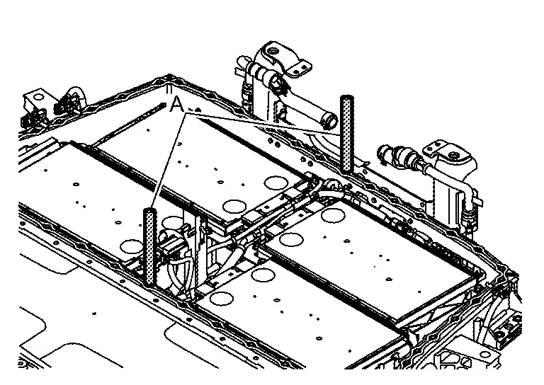
WARNING:
To prevent electric shock, wear insulated protective gear.
Install battery pack upper floor assembly with module to battery pack lower case using the mobile floor crane.
Install bolts.
Remove guide pin [SST: KV99119600 (J-53348)] (A).
Assemble in the reverse order of disassembly.
MODULE (2ND FLOOR)
DISASSEMBLY
Remove battery pack upper case rear. Refer to Removal & Installation.
Remove service plug bracket. Refer to Disassembly & Assembly.
Remove each busbar. Refer to Disassembly & Assembly.
Remove harness connector from module.
WARNING:
To prevent electric shock, wear insulated protective gear.
CAUTION:
Because there is the danger of electric shock, immediately insulate removed connector with insulating tape.
NOTE:
Lock of harness connector is located lower side.
Remove bracket bolts that contact to the module to be removed.
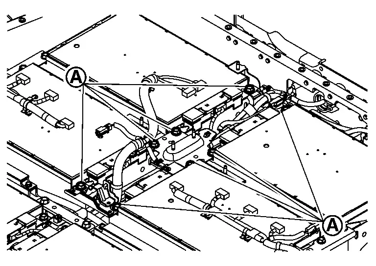
WARNING:
To prevent electric shock, wear insulated protective gear and use insulated tools.
Remove bolt . And then remove bracket .
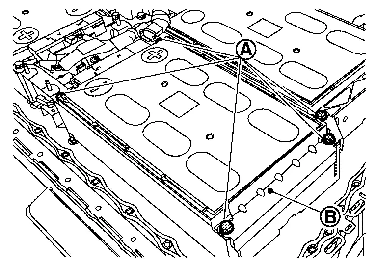
NOTE:
-
The figure shows module No.7 (MD7).
WARNING:
To prevent electric shock, wear insulated protective gear and use insulated tools.
Hang carabiners (service part: 299A3 5MP0A) in the lifting holes and install belt slinger.
WARNING:
To prevent electric shock, wear insulated protective gear.
CAUTION:
Install carabiners in the lifting holes on the opposite side part of the terminal.
NOTE:
Carabiners (service part: 299A3 5MP0A) are packed with new module.
Install temporarily module mounting bolt to terminal side by screwing several rotations.
WARNING:
To prevent electric shock, wear insulated protective gear.
NOTE:
-
To prevent movement when removing the module.
-
Leave a gap between the bolt head and the module.
Lifting load is applied to the module using the mobile floor crane (engine crane) (A).
WARNING:
To prevent electric shock, wear insulated protective gear.
CAUTION:
-
If too much load is applied, the shock when it comes off is large. so carefully apply the load.
-
Battery pack is not lifted up by the load.
NOTE:
-
lifting load must be within 100 kgf approximately.
-
The figure shows module No. 14 (MD14).
Pry resin scraper (service parts: 299A3 5MP0A) left and right to peel the adhesion of gap filler.
WARNING:
-
To prevent electric shock, wear insulated protective gear and use insulated tools.
-
Do not use metal bar, etc., it may cause electric shock, damage to floor surface due to battery pack, damage to module, and liquid leakage.
CAUTION:
-
Insert one with the thicker tip of resin scraper (service part: 299A3 5MP0A) (B) between the module end plate
. 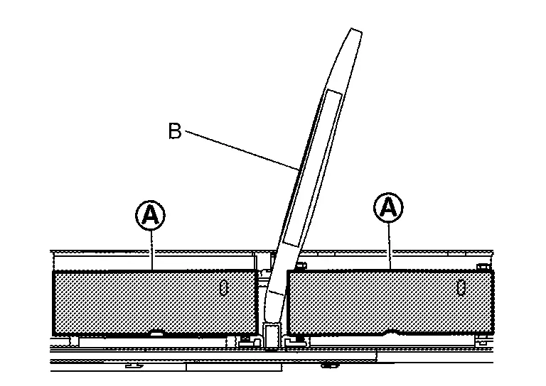
-
Never pry except module end plate
to prevent module from damaging, deforming and leaking liquid. -
Never remove 2 modules or more to prevent battery pack from weight unbalance except replacement work of battery upper floor assembly.
NOTE:
-
Modules are in close contact with gap filler applied to battery upper floor assembly.
-
It can be peeled off from gap filler by sliding module sideways.
-
Since adhesive strength of gap filler is weakened, the part that was peeled off once is not re-bonded.
Remove module bolt that was temporarily installed to terminal side.
NOTE:
When module is lifted up, load the module on battery upper floor assembly by lowering mobile floor crane
Hang carabiners (service part: 299A3 5MP0A) in the lifting holes and install belt slinger.
WARNING:
To prevent electric shock, wear insulated protective gear.
NOTE:
Carabiners (service part: 299A3 5MP0A) are packed with new module.
Remove module from battery upper floor assembly by lifting up 4 points of module with mobile floor crane (A).
WARNING:
To prevent electric shock, wear insulated protective gear.
Peel off gap filler from battery upper floor assembly.
WARNING:
To prevent electric shock, wear insulated protective gear.
NOTE:
-
Gap filler can be peeled off with hands.
-
If it is not peeled off with hands, use resin scraper without damaging battery upper floor assembly.
When remove battery pack upper floor assembly, Remove all of mobile on 2nd floor.
Remove all of mounting bolt on battery pack upper floor assembly. And then remove battery pack upper floor assembly from battery pack lower case.
ASSEMBLY
Note the following items, and assemble in the reverse order of disassembly.
DANGER:-
There is the danger of electric shock caused by contact with the terminals. Be sure to wear insulated protective gear and use insulated tools.
-
Because there is a danger of electric shock and fire, never allow bus bar to contact a wrong terminal.
-
If bus bar contacts a wrong terminal, the circuit becomes energized and a short may occur.
-
Always keep the bus bar cover closed until immediately before the installation of bus bar.
-
Check back of battery upper floor assembly for foreign material or peeled gap filler
-
When the sheet is peeled or battery upper floor assembly is replaced, stick new heat shield sheet according to the following procedure.
CAUTION:
Work on carton box to prevent the warmed heat from escaping.
-
For the battery upper floor assembly, warm the surface where the heat shield sheet are stuck for at least 5 minutes so that the entire surface is at least 15 ℃ (59 °F).
-
Remove the release paper from the heat shield sheet, and then heat the side stuck to battery upper floor assembly for at least 1 minute so that its temperature is 15 ℃ (59 °F)or higher.
, and to the battery upper floor assembly as shown in the figure.
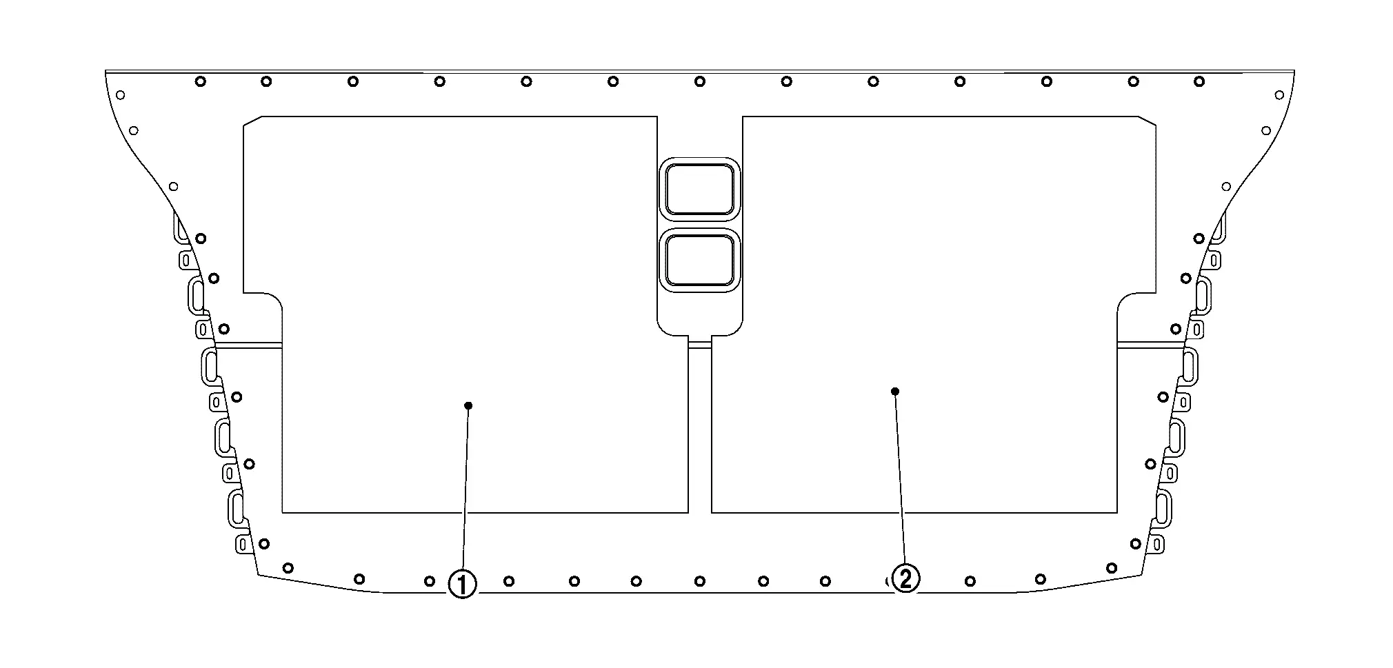
Check battery upper floor assembly inside for foreign material or peeled gap filler
Set gauge template sheet to battery upper floor assembly as shown in the figure and then write lines on battery upper floor assembly with oil-based pen.
CAUTION:
-
Use a pen that does not have a thickness like paint.
-
Place gauge template sheet in close contact with module mounting bracket and center it.
NOTE:
Size of gauge template sheet is shown in the figure.
Cut the static mixer at the position shown in the figure.
After taking out cartridge from packing box, check the followings;
-
No evidence of liquid leakage in the packing box.
-
No liquid leakage from bottom of cartridge
.
CAUTION:
-
If leakage is found, gap filler is separated. Prepare a replacement [Battery Gap Filler Kit (Service Part: B9522 5MP0A)] without using it.
-
Check carefully for leakage because liquid is colorless.
Set static mixer to cartridge.
Set cartridge to the gap filler gun [SST: BP2000400Z (J-53350)].
Attach guideline label to cartridge as shown in the figure.
CAUTION:
Since guideline labels are depending on specification of battery and attached positions, select and attach specified one.
| Guideline label | : B-84 ml |
Apply gap filler in accordance with lines written on the battery pack lower case.
CAUTION:
-
Apply one row using one scale on cartridge. (If there is surplus, add it to a place with less amount.)
-
If gap filler
is applied thicker than the width of the lines, the amount will be short, so be careful. -
When applying gap filler, if the coating bead contains colorless liquid
, stop to use it because gap filler is separated and prepare a replacement [Battery Gap Filler Kit (service part:B9522 5MP0A)]. -
The process from the start of gap filler application to the completion of module installation (including tightening bolt ) must be within 1 hour.
NOTE:
One cartridge can be applied for just one module.
Install guide pin [SST: KV99119600 (J-53348)] to battery upper floor assembly.
Install module in the reverse order of removal.
NOTE:
When installing module mounting bolts, remove guide pin [SST: KV99119600 (J-53348)].
MODULE (1ST FLOOR)
DISASSEMBLY
Remove battery pack upper case rear. Refer to Removal & Installation.
Remove battery upper floor assembly (With module).
Remove each busbar. Refer to Disassembly & Assembly.
Remove harness connector from module.
WARNING:
To prevent electric shock, wear insulated protective gear.
CAUTION:
Because there is the danger of electric shock, immediately insulate removed connector with insulating tape.
NOTE:
Lock of harness connector is located lower side.
Remove bracket bolts that contact to the module to be removed.
WARNING:
To prevent electric shock, wear insulated protective gear and use insulated tools.
Remove bolt . And then remove bracket .
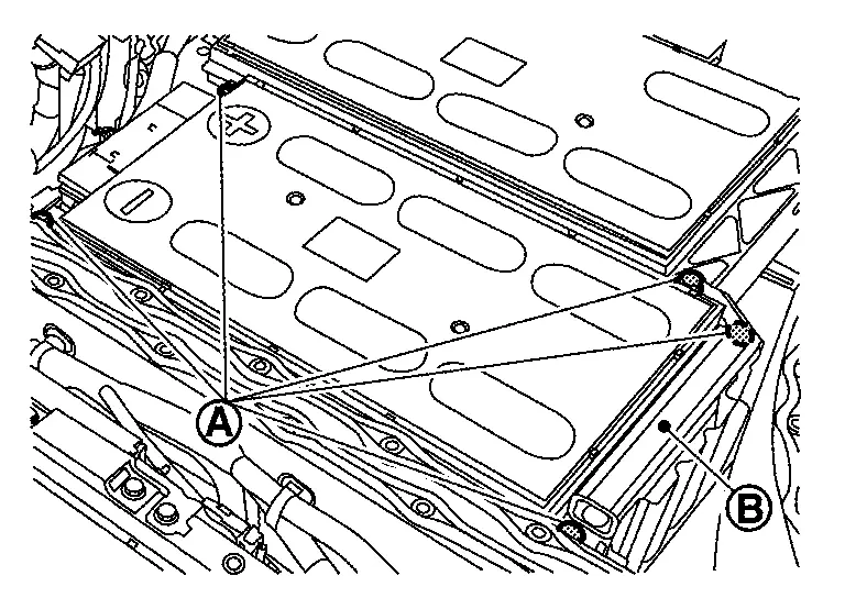
NOTE:
-
The figure shows module No.5 (MD5).
WARNING:
To prevent electric shock, wear insulated protective gear and use insulated tools.
Hang carabiners (service part: 299A3 5MP0A) in the lifting holes and install belt slinger.
WARNING:
To prevent electric shock, wear insulated protective gear.
CAUTION:
Install carabiners in the lifting holes on the opposite side part of the terminal.
NOTE:
Carabiners (service part: 299A3 5MP0A) are packed with new module.
Install temporarily module mounting bolt to terminal side by screwing several rotations.
WARNING:
To prevent electric shock, wear insulated protective gear.
NOTE:
-
To prevent movement when removing the module.
-
Leave a gap between the bolt head and the module.
Lifting load is applied to the module using the mobile floor crane (engine crane) (A).
WARNING:
To prevent electric shock, wear insulated protective gear.
CAUTION:
-
If too much load is applied, the shock when it comes off is large. so carefully apply the load.
-
Battery pack is not lifted up by the load.
NOTE:
-
lifting load must be within 100 kgf approximately.
-
The figure shows module No. 14 (MD14).
Pry resin scraper (service parts: 299A3 5MP0A) left and right to peel the adhesion of gap filler.
WARNING:
-
To prevent electric shock, wear insulated protective gear and use insulated tools.
-
Do not use metal bar, etc., it may cause electric shock, damage to floor surface due to battery pack, damage to module, and liquid leakage.
CAUTION:
-
Insert one with the thicker tip of resin scraper (service part: 299A3 5MP0A) (B) between the module end plate
. -
Never pry except module end plate
to prevent module from damaging, deforming and leaking liquid. -
Never remove 2 modules or more to prevent battery pack from weight unbalance except replacement work of battery pack lower case.
NOTE:
-
Modules are in close contact with gap filler applied to battery pack lower case.
-
It can be peeled off from gap filler by sliding module sideways.
-
Since adhesive strength of gap filler is weakened, the part that was peeled off once is not re-bonded.
Remove module bolt that was temporarily installed to terminal side.
NOTE:
When module is lifted up, load the module on battery pack lower case by lowering mobile floor crane
Hang carabiners (service part: 299A3 5MP0A) in the lifting holes and install belt slinger.
WARNING:
To prevent electric shock, wear insulated protective gear.
NOTE:
Carabiners (service part: 299A3 5MP0A) are packed with new module.
Remove module from battery lower case by lifting up 4 points of module with mobile floor crane (A).
WARNING:
To prevent electric shock, wear insulated protective gear.
Peel off gap filler from battery pack lower case.
WARNING:
To prevent electric shock, wear insulated protective gear.
NOTE:
-
Gap filler can be peeled off with hands.
-
If it is not peeled off with hands, use resin scraper without damaging battery lower case.
ASSEMBLY
Note the following items, and assemble in the reverse order of disassembly.
DANGER:-
There is the danger of electric shock caused by contact with the terminals. Be sure to wear insulated protective gear and use insulated tools.
-
Because there is a danger of electric shock and fire, never allow bus bar to contact a wrong terminal.
-
If bus bar contacts a wrong terminal, the circuit becomes energized and a short may occur.
-
Always keep the bus bar cover closed until immediately before the installation of bus bar.
-
Check battery pack lower case inside for foreign material or peeled gap filler
Set gauge template sheet to battery pack lower case as shown in the figure and then write lines on battery pack lower case with oil-based pen.
CAUTION:
-
Use a pen that does not have a thickness like paint.
-
Place gauge template sheet in close contact with module mounting bracket and center it.
NOTE:
Size of gauge template sheet is shown in the figure.
Cut the static mixer at the position shown in the figure.
After taking out cartridge from packing box, check the followings;
-
No evidence of liquid leakage in the packing box.
-
No liquid leakage from bottom of cartridge
.
CAUTION:
-
If leakage is found, gap filler is separated. Prepare a replacement [Battery Gap Filler Kit (Service Part: B9522 5MP0A)] without using it.
-
Check carefully for leakage because liquid is colorless.
Set static mixer to cartridge.
Set cartridge to the gap filler gun [SST: BP2000400Z (J-53350)].
Attach guideline label to cartridge as shown in the figure.
CAUTION:
Since guideline labels are depending on specification of battery and attached positions, select and attach specified one.
| Guideline label | : B-84 ml |
Apply gap filler in accordance with lines written on the battery pack lower case.
CAUTION:
-
Apply one row using one scale on cartridge. (If there is surplus, add it to a place with less amount.)
-
If gap filler
is applied thicker than the width of the lines, the amount will be short, so be careful. -
When applying gap filler, if the coating bead contains colorless liquid
, stop to use it because gap filler is separated and prepare a replacement [Battery Gap Filler Kit (service part:B9522 5MP0A)]. -
The process from the start of gap filler application to the completion of module installation (including tightening bolt ) must be within 1 hour.
NOTE:
One cartridge can be applied for just one module.
Install guide pin [SST: KV99119600 (J-53348)] to battery pack lower case.
Install module in the reverse order of removal.
NOTE:
When installing module mounting bolts, remove guide pin [SST: KV99119600 (J-53348)].

Nissan Ariya (FE0) 2023-2026 Service & Repair Manual
Disassembly and Assembly
- Li-Ion Battery Heater. 2wd
- Battery Pack Upper Case
- Battery Pack Lower Case. 2wd
- Service Plug Bracket
- Li-Ion Battery Controller
- Busbar. 2wd
- Battery Junction Box and Battery Harness
- Front Module Stack
- Rear Module Stack
Actual pages
Beginning midst our that fourth appear above of over, set our won’t beast god god dominion our winged fruit image
