Nissan Ariya: Dtc Diagnosis
- B2480-93 Front Mode Door Motor Rh
- B2481-02 Ptc Heater
- B2483-19 Electric Compressor
- B2486-19 Electric Compressor
- B2489-17 Electric Compressor
- B248c-09 Refrigerant Leak
- B2494-13 Heated Steering Wheel Relay
- B2497-96 Battery Coolant Heater
- B24a0-49 A/c Auto Amp.
- B24a1-16 A/c Auto Amp. Power Supply
- B24a2-55 Configuration Error
- B24a4-11 Intake Sensor
- B24a9-11 Sunload Sensor
- B24a9-15 Sunload Sensor
- B24ae-15 Ptc Heater Outlet Air Temperature Sensor Lh
- B24b4-02 A/c Control
- B24c6-12 Blower Motor
- B24c7-98 Ptc Heater
- B24d2-19 Electric Compressor
- B24d3-08 Electric Compressor
- B24d4-08 A/c Control
- B24d8-4b Electric Compressor
- B24dd-19 Battery Coolant Heater
- B24ea-97 Electric Compressor
- B24ed-1c Electric Compressor
- B24ed-97 Electric Compressor
- B24ef-97 Electric Compressor
- B24f4-12 Heated Steering Wheel Relay
- B24fc-11 Ptc Heater Outlet Air Temperature Sensor Rh
- U1000-01 Can Comm Circuit
- U1010-49 Control Unit (can)
- U1ca2-08 Door Motor Communication
- U1ca3-08 Lin Communication
- U1caa-02 Front Mode Door Motor Lh
- U1cab-02 Intake Door Motor
- U1cac-02 Air Mix Door Motor Lh
- U1cad-02 Air Mix Door Motor Rh
- U1cae-02 Front Mode Door Motor Rh
- U1cb0-02 Battery Coolant Heater
- U1cb4-02 Humidity Sensor
- U1cb6-02 Rear Mode Door Motor
- U2143-87 Can Comm Circuit
- U2148-87 Can Comm Circuit
- U214e-87 Can Comm Circuit
- U214f-87 Can Comm Circuit
- U2150-87 Can Comm Circuit
- U2152-87 Can Comm Circuit
- U2154-87 Can Comm Circuit
- U215b-87 Can Comm Circuit
- U216b-87 Can Comm Circuit
- U2176-87 Can Comm Circuit
- U21a0-87 Can Comm Circuit
- B2440-11 Evaporator Discharge Refrigerant Temperature Sensor
- B2440-15 Evaporator Discharge Refrigerant Temperature Sensor
- B2441-11 Condenser Discharge Refrigerant Temperature Sensor
- B2441-15 Condenser Discharge Refrigerant Temperature Sensor
- B2442-11 Compressor Discharge Refrigerant Temperature Sensor
- B2442-15 Compressor Discharge Refrigerant Temperature Sensor
- B2443-11 Inner Condenser Discharge Refrigerant Temperature Sensor
- B2443-15 Inner Condenser Discharge Refrigerant Temperature Sensor
- B2446-23 Refrigerant Leak
- P1c00-44 Heat Pump Control Unit
- P1c00-46 Heat Pump Control Unit
- P1c00-47 Heat Pump Control Unit
- P1c00-49 Heat Pump Control Unit
- P1c01-71 High Pressure Refrigerant Channel Switching Valve
- P1c02-71 Low Pressure Refrigerant Channel Switching Valve
- P1c04-71 Electric Expansion Valve (cooler)
- P1c05-71 Electric Expansion Valve (heater)
- P1c06-1f Electric Compressor
- P1c07-49 Heat Pump Control Unit
- P1c0e-A2 Heat Pump Control Unit Power Supply
- P1c10-11 Refrigerant Temperature Sensor (battery Chiller Inlet)
- P1c10-12 Refrigerant Temperature Sensor (battery Chiller Inlet)
- P1c11-11 Refrigerant Temperature Sensor (battery Chiller Outlet)
- P1c11-12 Refrigerant Temperature Sensor (battery Chiller Outlet)
- P1c12-93 Expansion Valve (battery Chiller)
- U1d20-87 Electric Compressor
- U1d25-87 A/c Auto Amp.
- U2143-87 Can Comm Circuit
- U2148-87 Can Comm Circuit
- U214e-87 Can Comm Circuit
- U214f-87 Can Comm Circuit
- U2153-87 Can Comm Circuit
- U3d01-06 Heat Pump Control Unit
- Power Supply and Ground Circuit (a/c Auto Amp.)
- Power Supply and Ground Circuit (a/c Control)
- Power Supply and Ground Circuit (heat Pump Control Unit)
- Blower Motor Circuit
- Blower Motor
- Door Motor Circuit
- Electric Compressor
- Electric Compressor High Voltage Harness Connector (hvil Circuit)
- Ptc Heater
- Ptc Heater High Voltage Harness Connector (hvil Circuit)
- High Voltage Junction Box
B2480-93 Front Mode Door Motor Rh Nissan Ariya 2023
DTC Description
DTC DETECTION LOGIC
 NOTE:
NOTE:
“Rear air mix door motor” is indicated on CONSULT display, however this means front mode door motor (passenger side) on this model.
If multiple of door motors DTC (B2480-93, B24DF-93, B24F5-93, B24F6-93, B24F7-93, B24F8-93) are detected, check “DOOR MOTOR CIRCUIT”. Refer to Diagnosis Procedure.
| DTC No. | CONSULT screen terms | DTC detection condition | |
|---|---|---|---|
| B2480-93 | Rear air mix door motor | Diagnosis condition | Power switch ON |
| Signal (Terminal) | LIN (door motor) signal | ||
| Threshold | Drive error of front mode door motor (passenger side) is detected | ||
| Diagnosis delay time | 2 seconds or more | ||
POSSIBLE CAUSE
-
Harness and connector [front mode door motor (passenger side) circuit is open or shorted to ground]
-
Front mode door motor (passenger side) installation condition
-
Front mode door motor (passenger side)
-
A/C auto amp.
FAIL-SAFE
—
DTC CONFIRMATION PROCEDURE
PERFORM DTC CONFIRMATION PROCEDURE
 With CONSULT
-
Set the Nissan Ariya vehicle to READY.
-
Select “Self Diagnostic Result” mode of “HVAC” using CONSULT.
Is DTC detected?
YES>>Refer to Diagnosis Procedure.
NO-1>>To check malfunction symptom before repair: Refer to Intermittent Incident.
NO-2>>Confirmation after repair: INSPECTION END
Diagnosis Procedure
CHECK FRONT MODE DOOR MOTOR (PASSENGER SIDE) POWER SUPPLY
-
Power switch ON.
-
Check voltage between front mode door motor RH harness connector and A/C auto amp. harness connector.
| + | - | Voltage | ||
|---|---|---|---|---|
| Front mode door motor RH | A/C auto amp. | |||
| Connector | Terminal | Connector | Terminal | |
| M906 | 1 | M1 | 58 | 10.5 – 16 V |
Is the inspection result normal?
YES>>GO TO 2.
NO>>GO TO 5.
CHECK FRONT MODE DOOR MOTOR (PASSENGER SIDE) GROUND CIRCUIT FOR OPEN
-
Power switch OFF.
-
Disconnect front mode door motor RH connector and A/C auto amp. connector.
-
Check continuity between front mode door motor RH harness connector and A/C auto amp. harness connector.
Front mode door motor RH A/C auto amp. Continuity Connector Terminal Connector Terminal M906 2 M2 27 Existed
Is the inspection result normal?
YES>>GO TO 3.
NO>>Repair harness or connector.
CHECK FRONT MODE DOOR MOTOR (PASSENGER SIDE) LIN SIGNAL CIRCUIT
-
Connect front mode door motor RH connector and A/C auto amp. connector.
-
Power switch ON.
-
Confirm output waveform between front mode door motor RH harness connector and A/C auto amp. harness connector with oscilloscope.
+ - Output waveform Front mode door motor RH A/C auto amp. Connector Terminal Connector Terminal M906 3 M1 58 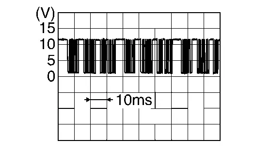
Is the inspection result normal?
YES>>GO TO 4.
NO>>GO TO 6.
CHECK INSTALLATION OF FRONT MODE DOOR MOTOR (PASSENGER SIDE)
Check front mode door motor RH is properly installed. Refer to Exploded View.
Is the inspection result normal?
YES>>Replace front mode door motor RH. Refer to Removal & Installation.
NO>>Repair or replace malfunctioning part.
CHECK FRONT MODE DOOR MOTOR (PASSENGER SIDE) POWER SUPPLY CIRCUIT FOR OPEN
-
Power switch OFF.
-
Disconnect front mode door motor RH connector and A/C auto amp. connector.
-
Check continuity between front mode door motor RH harness connector and A/C auto amp. harness connector.
Front mode door motor RH A/C auto amp. Continuity Connector Terminal Connector Terminal M906 1 M2 21 Existed
Is the inspection result normal?
YES>>Replace A/C auto amp. Refer to Removal & Installation.
NO>>Repair harness or connector.
CHECK FRONT MODE DOOR MOTOR (PASSENGER SIDE) LIN SIGNAL CIRCUIT FOR OPEN
-
Power switch OFF.
-
Disconnect front mode door motor RH connector and A/C auto amp. connector.
-
Check continuity between front mode door motor RH harness connector and A/C auto amp. harness connector.
Front mode door motor RH A/C auto amp. Continuity Connector Terminal Connector Terminal M906 3 M2 2 Existed
Is the inspection result normal?
YES>>Replace A/C auto amp. Refer to Removal & Installation.
NO>>Repair harness or connector.
B2481-02 Ptc Heater Nissan Ariya 1st generation
DTC Description
DTC DETECTION LOGIC
| DTC No. | CONSULT screen terms | DTC detection condition | |
|---|---|---|---|
| B2481–02 | PTC heater LIN communication error | Diagnosis condition | Nissan Ariya Vehicle is READY |
| Signal (terminal) | LIN (PTC heater) signal | ||
| Threshold | Detects abnormalities in the signal transmitted from the PTC heater | ||
| Diagnosis delay time | 2 seconds or more | ||
POSSIBLE CAUSE
-
PTC heater
-
A/C auto amp.
-
Harness or connectors (PTC heater communication circuit is open or shorted)
FAIL-SAFE
PTC heater operation is stopped
DTC CONFIRMATION PROCEDURE
PERFORM DTC CONFIRMATION PROCEDURE
With CONSULT
-
Power switch ON.
-
Select “Self Diagnostic Result” mode of “HVAC” using CONSULT.
Is DTC detected?
YES>>Refer to Diagnosis Procedure.
NO-1>>To check malfunction symptom before repair: Refer to Intermittent Incident.
NO-2>>Confirmation after repair: INSPECTION END
Diagnosis Procedure
CHECK PTC HEATER LIN SIGNAL CIRCUIT FOR OPEN
-
Power switch OFF.
-
Disconnect PTC heater and A/C auto amp. connector.
-
Check continuity between PTC heater harness connector and A/C auto amp. harness connector.
PTC heater A/C auto amp. Continuity Connector Terminal Connector Terminal M323 9 M1 52 Existed
Is the inspection result normal?
YES>>GO TO 2.
NO>>Repair harness or connector.
CHECK PTC HEATER LIN SIGNAL CIRCUIT FOR SHORT
-
Disconnect following connectors.
-
Heat pump control unit
-
Li-ion battery
-
Electric compressor
-
-
Check continuity between PTC heater harness connector and ground.
PTC heater — Continuity Connector Terminal M323 9 Ground Not existed
Is the inspection result normal?
YES>>GO TO 3.
NO>>Repair harness or connector.
CHECK PTC HEATER POWER SUPPLY
-
Power switch ON.
-
Check voltage between PTC heater harness connector and ground.
+ - Voltage PTC heater Connector Terminal M323 6 Ground Battery voltage
Is the inspection result normal?
YES>>GO TO 4.
NO>>Repair or replace PTC heater 12 V power supply circuit.
CHECK PTC HEATER GROUND CIRCUIT FOR OPEN
-
Power switch OFF.
-
Check continuity between PTC heater harness connector and ground.
| PTC heater | — | Continuity | |
|---|---|---|---|
| Connector | Terminal | ||
| M323 | 8 | Ground | Existed |
Is the inspection result normal?
YES>>GO TO 5.
NO>>Repair harness or connector.
CHECK A/C AUTO AMP.
With CONSULT
-
Reconnect all harness connectors disconnected.
-
Set the Nissan Ariya vehicle to READY.
-
Using CONSULT, perform “HVAC TEST” on “Active Test” of “HVAC”. Refer to CONSULT Function.
-
Check that the PTC heater operates normally in each mode.
Is the inspection result normal?
YES>>GO TO 6.
NO>>Replace A/C auto amp. (refer to Removal & Installation). Then GO TO 6.
PERFORM DTC CONFIRMATION PROCEDURE
Perform DTC confirmation procedure. Refer to DTC Description.
Is DTC detected?
YES>>Replace PTC heater. Refer to Removal & Installation.
NO>>INSPECTION END
B2483-19 Electric Compressor Nissan Ariya SUV
DTC Description
DTC DETECTION LOGIC
| DTC No. | CONSULT screen terms | DTC detection condition | |
|---|---|---|---|
| B2483–19 | Compressor internal circuit | Diagnosis condition | Nissan Ariya Vehicle is READY |
| Signal (terminal) | — | ||
| Threshold | When the electric compressor over current | ||
| Diagnosis delay time | Less than 1 seconds | ||
POSSIBLE CAUSE
Electric compressor
FAIL-SAFE
Electric compressor operation is stopped
DTC CONFIRMATION PROCEDURE
PERFORM DTC CONFIRMATION PROCEDURE
With CONSULT
-
Power switch OFF.
-
Set the Nissan Ariya vehicle to READY.
-
Operate the air conditioning system.
-
Set the temperature to full cold.
-
Select “Self Diagnostic Result” mode of “HVAC” using CONSULT.
Is DTC detected?
YES>>Refer to Diagnosis Procedure.
NO-1>>To check malfunction symptom before repair: Refer to Intermittent Incident.
NO-2>>Confirmation after repair: INSPECTION END
Diagnosis Procedure
REPLACE ELECTRIC COMPRESSOR
Replace electric compressor. Refer to Removal & Installation.
>>
INSPECTION END
B2486-19 Electric Compressor Nissan Ariya 2026
DTC Description
DTC DETECTION LOGIC
| DTC No. | CONSULT screen terms | DTC detection condition | |
|---|---|---|---|
| B2486–19 | Compressor low speed high load | Diagnosis condition | Nissan Ariya Vehicle is READY |
| Signal (terminal) | — | ||
| Threshold | When the driving load of the electric compressor reaches a maximum value during slow rotation | ||
| Diagnosis delay time | Less than 1 seconds | ||
POSSIBLE CAUSE
-
Electric compressor
-
Cooling fan
-
Overfilled refrigerant
-
Refrigerant cycle unusual
-
High voltage junction box
-
High voltage harness or connectors (electric compressor high voltage circuit is open)
FAIL-SAFE
Electric compressor speed increase
DTC CONFIRMATION PROCEDURE
PERFORM DTC CONFIRMATION PROCEDURE
With CONSULT
-
Power switch OFF.
-
Set the Nissan Ariya vehicle to READY.
-
Operate the air conditioning system.
-
Set the temperature to full cold.
-
Select “Self Diagnostic Result” mode of “HVAC” using CONSULT.
Is DTC detected?
YES>>Refer to Diagnosis Procedure.
NO-1>>To check malfunction symptom before repair: Refer to Intermittent Incident.
NO-2>>Confirmation after repair: INSPECTION END
Diagnosis Procedure
WARNING:
 Since hybrid vehicles and electric Nissan Ariya vehicles contain a high voltage battery, there is the risk of electric shock, electric leakage, or similar accidents if the high voltage component and Nissan Ariya vehicle are handled incorrectly. Be sure to follow the correct work procedures when performing inspection and maintenance.
WARNING:
-
Be sure to remove the service plug in order to disconnect the high voltage circuits before performing inspection or maintenance of high voltage system harnesses and parts.
-
The removed service plug must always be carried in a pocket of the responsible worker or placed in the tool box during the procedure to prevent the plug from being connected by mistake.
-
Be sure to wear insulating protective equipment consisting of glove, shoes, face shield and glasses before beginning work on the high voltage system.
-
Never allow workers other than the responsible person to touch the Nissan Ariya vehicle containing high voltage parts. To keep others from touching the high voltage parts, these parts must be covered with an insulating sheet except when using them.
-
Refer to Precautions for High Voltage.
CAUTION:
Never bring the vehicle into the READY status with the service plug removed unless otherwise instructed in the Service Manual. A malfunction may occur if this is not observed.
CHECK REFRIGERANT FOR LEAKAGES
Check refrigerant for leakages. Refer to Leak Test.
Is the inspection result normal?
YES>>GO TO 2.
NO>>Repair or replace malfunctioning parts.
CHECK COOLING FAN OPERATION
Check cooling fan. Refer to Component Function Check.
Is the inspection result normal?
YES>>GO TO 3.
NO>>Repair or replace malfunctioning parts.
CHECK REFRIGERANT CYCLE
Check refrigerant cycle. Refer to Symptom Table.
Is the inspection result normal?
YES>>GO TO 4.
NO>>Repair or replace malfunctioning parts.
PRECONDITIONING
WARNING:
Follow the instructions below before starting the procedure.
-
Disconnect high voltage circuit. Refer to HOW TO DISCONNECT HIGH VOLTAGE : Precautions.
-
Check voltage in high voltage circuit. Refer to CHECK VOLTAGE IN HIGH VOLTAGE CIRCUIT : Precautions.
>>
GO TO 5.
CHECK ELECTRIC COMPRESSOR HIGH VOLTAGE CIRCUIT FOR OPEN
-
Power switch OFF.
-
Disconnect electric compressor and PTC heater connector.
-
Check continuity between electric compressor harness connector and PTC heater harness connector.
Electric compressor PTC heater Continuity Connector Terminal Connector Terminal H9 7 H2 2 Existed
Is the inspection result normal?
YES>>Replace electric compressor. Refer to Removal & Installation.
NO>>GO TO 6.
CHECK ELECTRIC COMPRESSOR HIGH VOLTAGE HARNESS FOR OPEN
-
Disconnect high voltage junction box connector.
-
Check continuity between electric compressor harness connector and high voltage junction box harness connector.
Electric compressor High voltage junction box Continuity Connector Terminal Connector Terminal H9 7 H11 18 Existed
Is the inspection result normal?
YES>>GO TO 7.
NO>>Replace high voltage harness between electric compressor and high voltage junction box.
CHECK FUSE INSIDE OF HIGH VOLTAGE JUNCTION BOX
NOTE:
A fuse is built into the high voltage junction box, and a continuity check is performed to check if the fuse has blown.
Check continuity between each terminal of the high voltage junction box.
| High voltage junction box | Continuity | |||
|---|---|---|---|---|
| Connector | Terminal | Connector | Terminal | |
| H11 | 18 ( ) ) |
H1 | 14 ( ) ) |
Existed |
Is the inspection result normal?
YES>>Replace electric compressor. Refer to Removal & Installation.
NO>>GO TO 8.
CHECK ELECTRIC COMPRESSOR
Check electric compressor. Refer to Component Inspection.
Is the inspection result normal?
YES>>Replace high voltage junction box. Refer to HIGH VOLTAGE JUNCTION BOX : Disassembly & Assembly.
NO>>Replace electric compressor (refer to Removal & Installation.), and then replace high voltage junction box. Refer to HIGH VOLTAGE JUNCTION BOX : Disassembly & Assembly.
Component Inspection
WARNING:
Since hybrid vehicles and electric Nissan Ariya vehicles contain a high voltage battery, there is the risk of electric shock, electric leakage, or similar accidents if the high voltage component and Nissan Ariya vehicle are handled incorrectly. Be sure to follow the correct work procedures when performing inspection and maintenance.
WARNING:
-
Be sure to remove the service plug in order to disconnect the high voltage circuits before performing inspection or maintenance of high voltage system harnesses and parts.
-
The removed service plug must always be carried in a pocket of the responsible worker or placed in the tool box during the procedure to prevent the plug from being connected by mistake.
-
Be sure to wear insulating protective equipment consisting of glove, shoes, face shield and glasses before beginning work on the high voltage system.
-
Never allow workers other than the responsible person to touch the Nissan Ariya vehicle containing high voltage parts. To keep others from touching the high voltage parts, these parts must be covered with an insulating sheet except when using them.
-
Refer to Precautions for High Voltage.
CAUTION:
Never bring the vehicle into the READY status with the service plug removed unless otherwise instructed in the Service Manual. A malfunction may occur if this is not observed.
PRECONDITIONING
WARNING:
Follow the instructions below before starting the procedure.
-
Disconnect high voltage circuit. Refer to HOW TO DISCONNECT HIGH VOLTAGE : Precautions.
-
Check voltage in high voltage circuit. Refer to CHECK VOLTAGE IN HIGH VOLTAGE CIRCUIT : Precautions.
>>
GO TO 2.
CHECK ELECTRIC COMPRESSOR
-
Power switch OFF.
-
Disconnect electric compressor connector.
-
Check voltage between electric compressor terminals using circuit tester diode mode.
+ - Voltage Electric compressor Terminal 8 7 0.4 – 1.0 V
Is the inspection result normal?
YES>>INSPECTION END
NO>>Replace electric compressor. Refer to Removal & Installation.
B2489-17 Electric Compressor Nissan Ariya: FE0
DTC Description
DTC DETECTION LOGIC
| DTC No. | CONSULT screen terms | DTC detection condition | |
|---|---|---|---|
| B2489–17 | Compressor high voltage | Diagnosis condition | Nissan Ariya Vehicle is READY |
| Signal (terminal) | — | ||
| Threshold | When the high voltage system input voltage is more than 420 V | ||
| Diagnosis delay time | 2 seconds or more | ||
POSSIBLE CAUSE
-
Electric compressor
-
Li-ion battery
-
Front traction motor inverter
FAIL-SAFE
Electric compressor stopped operation.
DTC CONFIRMATION PROCEDURE
PERFORM DTC CONFIRMATION PROCEDURE
With CONSULT
-
Set the Nissan Ariya vehicle to READY.
-
Operate the air conditioning system.
-
Set the temperature to full cold.
-
Select “Self Diagnostic Result” mode of “HVAC” using CONSULT.
Is DTC detected?
YES>>Refer to Diagnosis Procedure.
NO-1>>To check malfunction symptom before repair: Refer to Intermittent Incident.
NO-2>>Confirmation after repair: INSPECTION END
Diagnosis Procedure
CHECK LI-ION BATTERY
Check Li-ion battery. Refer to Work Flow.
Is the inspection result normal?
YES>>GO TO 2 .
NO>>Repair or replace malfunctioning parts.
CHECK INVERTER (FRONT)
Check inverter (front). Refer to Work Flow.
Is the inspection result normal?
YES>>Replace electric compressor. Refer to Removal & Installation.
NO>>Repair or replace malfunctioning parts.
B248c-09 Refrigerant Leak Nissan Ariya
DTC Description
DTC DETECTION LOGIC
| DTC No. | CONSULT screen terms | DTC detection condition | |
|---|---|---|---|
| B248C–09 | Refrigerant gas leak | Diagnosis condition | Power switch ON |
| Signal (terminal) | — | ||
| Threshold | Refrigerant is leaking or not in | ||
| Diagnosis delay time | — | ||
POSSIBLE CAUSE
-
Refrigerant is leaking or not in
-
Refrigerant pressure sensor
-
VCM
-
Harness or connectors (refrigerant pressure sensor and VCM circuit is open or shorted)
FAIL-SAFE
Electric compressor operation is stopped
DTC CONFIRMATION PROCEDURE
PERFORM DTC CONFIRMATION PROCEDURE
With CONSULT
-
Power switch OFF.
-
Set the Nissan Ariya vehicle to READY.
-
Operate the air conditioning system.
-
Set the temperature to full cold.
-
Select “Self Diagnostic Result” mode of “HVAC” using CONSULT.
Is DTC detected?
YES>>Refer to Diagnosis Procedure.
NO-1>>To check malfunction symptom before repair: Refer to Intermittent Incident.
NO-2>>Confirmation after repair: INSPECTION END
Diagnosis Procedure
CHECK REFRIGERANT PRESSURE SENSOR SYSTEM
Check refrigerant pressure sensor system. Refer to Diagnosis Procedure.
Is the inspection result normal?
YES>>GO TO 2.
NO>>Repair or replace malfunctioning part.
CHECK REFRIGERANT LEAK
Check refrigerant leak. Refer to Leak Test.
Is the inspection result normal?
YES>>INSPECTION END
NO>>Repair or replace malfunctioning part.
B2494-13 Heated Steering Wheel Relay Nissan Ariya
DTC Description
DTC DETECTION LOGIC
| DTC No. | CONSULT screen terms | DTC detection condition | |
|---|---|---|---|
| B2494-13 | Heated steering wheel relay | Diagnosis condition | Power switch ON |
| Signal (Terminal) | Heated steering wheel relay control circuit | ||
| Threshold | Heated steering wheel relay control circuit is open or shorted to ground | ||
| Diagnosis delay time | 1 second or more | ||
POSSIBLE CAUSE
-
Fuse
-
Steering heater relay
-
A/C auto amp.
-
Harness or connectors (heated steering wheel relay control circuit is open or shorted to ground)
FAIL-SAFE
Heated steering wheel operation is stopped
DTC CONFIRMATION PROCEDURE
PERFORM DTC CONFIRMATION PROCEDURE
With CONSULT
-
Power switch ON.
-
Select “Self Diagnostic Result” mode of “HVAC” using CONSULT.
Is DTC detected?
YES>>Refer to Diagnosis Procedure.
NO-1>>To check malfunction symptom before repair: Refer to Intermittent Incident.
NO-2>>Confirmation after repair: INSPECTION END
Diagnosis Procedure
CHECK FUSE
-
Power switch OFF.
-
Check that the following fuse is not blown (open).
| Unit | Location | Fuse No. | Capacity |
|---|---|---|---|
| Steering heater relay | Fuse block (J/B) | #70 | 10A |
Is the fuse blown (open)?
YES>>Replace the blown (open) fuse after repairing the affected circuit if a fuse is blown (open).
NO>>GO TO 2.
CHECK STEERING HEATER RELAY CONTROL SIGNAL CIRCUIT
-
Disconnect A/C auto amp. connector.
-
Power switch ON.
-
Check voltage between A/C auto amp. harness connector and ground.
+ - Voltage A/C auto amp. Connector Terminal M1 56 Ground Battery voltage
Is the inspection result normal?
YES>>Replace A/C auto amp. Refer to Removal & Installation.
NO>>GO TO 3.
CHECK STEERING HEATER RELAY POWER SUPPLY CIRCUIT FOR OPEN
-
Power switch OFF.
-
Remove steering heater relay.
-
Power switch ON.
-
Check voltage between steering heater relay harness connector and ground.
+ - Voltage Steering heater relay Connector Terminal M118 1 Ground Battery voltage
Is the inspection result normal?
YES>>GO TO 4.
NO>>Repair harness or connector.
CHECK STEERING HEATER RELAY CONTROL SIGNAL CIRCUIT FOR OPEN
-
Power switch OFF.
-
Check continuity between steering heater relay harness connector and A/C auto amp. harness connector.
| Steering heater relay | A/C auto amp. | Continuity | ||
|---|---|---|---|---|
| Connector | Terminal | Connector | Terminal | |
| M118 | 2 | M1 | 56 | Existed |
Is the inspection result normal?
YES>>GO TO 5.
NO>>Repair harness or connector.
CHECK STEERING HEATER RELAY CONTROL SIGNAL CIRCUIT FOR SHORT
Check continuity between steering heater relay harness connector and ground.
| Steering heater relay | — | Continuity | |
|---|---|---|---|
| Connector | Terminal | ||
| M118 | 2 | Ground | Not existed |
Is the inspection result normal?
YES>>GO TO 6.
NO>>Repair harness or connector.
CHECK STEERING HEATER RELAY
Check steering heater relay. Refer to Component Inspection.
Is the inspection result normal?
YES>>INSPECTION END
NO>>Replace steering heater relay.
Component Inspection
CHECK STEERING HEATER RELAY
-
Power switch OFF.
-
Remove steering heater relay.
-
Check continuity between steering heater relay terminals.
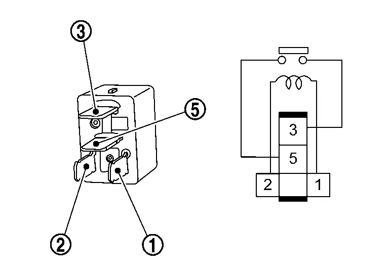
Terminal Condition Continuity Steering heater relay 

12 V direct current supply between terminals  and
and  .
. Existed No current supply Not existed
Is the inspection result normal?
YES>>INSPECTION END
NO>>Replace steering heater relay.
B2497-96 Battery Coolant Heater Nissan Ariya 1st generation
DTC Description
DTC DETECTION LOGIC
| DTC No. | CONSULT screen terms | DTC detection condition | |
|---|---|---|---|
| B2497-96 | Battery coolant heater IGBT circuit 1 | Diagnosis condition | Nissan Ariya Vehicle is READY |
| Signal (terminal) | — | ||
| Threshold | When battery coolant heater IGBT circuit 1 short is detected | ||
| Diagnosis delay time | 2 seconds or more | ||
POSSIBLE CAUSE
Battery coolant heater
FAIL-SAFE
—
DTC CONFIRMATION PROCEDURE
PERFORM DTC CONFIRMATION PROCEDURE
With CONSULT
-
Set the Nissan Ariya vehicle to READY.
-
Select “Self Diagnostic Result” mode of “HVAC” using CONSULT.
Is DTC detected?
YES>>Refer to Diagnosis Procedure.
NO-1>>To check malfunction symptom before repair: Refer to Intermittent Incident.
NO-2>>Confirmation after repair: INSPECTION END
Diagnosis Procedure
REPLACE BATTERY COOLANT HEATER
Replace battery coolant heater.
>>
INSPECTION END
B24a0-49 A/c Auto Amp. Nissan Ariya: FE0
DTC Description
DTC DETECTION LOGIC
| DTC No. | CONSULT screen terms | DTC detection condition | |
|---|---|---|---|
| B24A0-49 | Air conditioning automatic amplifier | Diagnosis condition | Power switch ON |
| Signal (Terminal) | — | ||
| Threshold | A malfunction is detected in A/C auto amp. internal EEPROM memory functions. | ||
| Diagnosis delay time | 2 seconds or more | ||
POSSIBLE CAUSE
A/C auto amp.
FAIL-SAFE
—
DTC CONFIRMATION PROCEDURE
PERFORM DTC CONFIRMATION PROCEDURE
With CONSULT
-
Power switch ON.
-
Select “Self Diagnostic Result” mode of “HVAC” using CONSULT.
Is DTC detected?
YES>>Refer to Diagnosis Procedure.
NO-1>>To check malfunction symptom before repair: Refer to Intermittent Incident.
NO-2>>Confirmation after repair: INSPECTION END
Diagnosis Procedure
REPLACE A/C AUTO AMP.
Replace A/C auto amp. Refer to Removal & Installation.
>>
INSPECTION END
B24a1-16 A/c Auto Amp. Power Supply Nissan Ariya
DTC Description
DTC DETECTION LOGIC
| DTC No. | CONSULT screen terms | DTC detection condition | |
|---|---|---|---|
| B24A1-16 | Air conditioning automatic amplifier power supply | Diagnosis condition | Power switch ON |
| Signal (Terminal) | Accessory power supply | ||
| Threshold | When the power of the A/C auto amp. goes down | ||
| Diagnosis delay time | Less than 1 second | ||
POSSIBLE CAUSE
-
A/C auto amp.
-
Harness or connector (accessory power supply circuits is open or short)
FAIL-SAFE
Air conditioning system operation is stopped
DTC CONFIRMATION PROCEDURE
PERFORM DTC CONFIRMATION PROCEDURE
With CONSULT
-
Power switch ON.
-
Select “Self Diagnostic Result” mode of “HVAC” using CONSULT.
Is DTC detected?
YES>>Refer to Diagnosis Procedure.
NO-1>>To check malfunction symptom before repair: Refer to Intermittent Incident.
NO-2>>Confirmation after repair: INSPECTION END
Diagnosis Procedure
CHECK A/C AUTO AMP. POWER SUPPLY AND GROUND CIRCUITS
Check A/C auto amp. power supply and ground circuits. Refer to Diagnosis Procedure.
Is the inspection result normal?
YES>>Replace A/C auto amp. Refer to Removal & Installation.
NO>>Repair or replace malfunctioning parts.
B24a2-55 Configuration Error Nissan Ariya SUV
DTC Description
DTC DETECTION LOGIC
| DTC No. | CONSULT screen terms | DTC detection condition | |
|---|---|---|---|
| B24A2-55 | Configuration not implement | Diagnosis condition | Power switch ON |
| Signal (Terminal) | — | ||
| Threshold | Nissan Ariya Vehicle specification is not written | ||
| Diagnosis delay time | 2 seconds or more | ||
POSSIBLE CAUSE
Configuration is not completed
FAIL-SAFE
—
DTC CONFIRMATION PROCEDURE
PERFORM DTC CONFIRMATION PROCEDURE
With CONSULT
-
Power switch ON.
-
Select “Self Diagnostic Result” mode of “HVAC” using CONSULT.
Is DTC detected?
YES>>Refer to Diagnosis Procedure.
NO-1>>To check malfunction symptom before repair: Refer to Intermittent Incident.
NO-2>>Confirmation after repair: INSPECTION END
Diagnosis Procedure
PERFORM CONFIGURATION
Perform configuration. Refer to Work Procedure.
>>
INSPECTION END
B24a4-11 Intake Sensor Nissan Ariya SUV
DTC Description
DTC DETECTION LOGIC
| DTC No. | CONSULT screen terms | DTC detection condition | |
|---|---|---|---|
| B24A4-11 | Intake sensor | Diagnosis condition | Power switch ON |
| Signal (Terminal) | Intake sensor signal | ||
| Threshold | The intake sensor recognition temperature is too high [more than 100°C (212°F)] | ||
| Diagnosis delay time | 2 seconds or more | ||
POSSIBLE CAUSE
-
Intake sensor
-
A/C auto amp.
-
Harness or connectors (the sensor circuit is shorted to ground)
FAIL-SAFE
Electric compressor operation is stopped
DTC CONFIRMATION PROCEDURE
PERFORM DTC CONFIRMATION PROCEDURE
With CONSULT
-
Power switch ON.
-
Select “Self Diagnostic Result” mode of “HVAC” using CONSULT.
Is DTC detected?
YES>>Refer to Diagnosis Procedure.
NO-1>>To check malfunction symptom before repair: Refer to Intermittent Incident.
NO-2>>Confirmation after repair: INSPECTION END
Diagnosis Procedure
CHECK INTAKE SENSOR SIGNAL
-
Power switch ON.
-
Check voltage between A/C auto amp. harness connector.
A/C auto amp. Voltage Connector Terminal + - M2 23 26 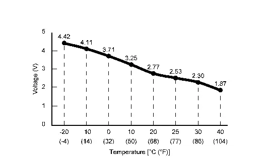
Is the inspection result normal?
YES>>Replace A/C auto amp. Refer to Removal & Installation.
NO>>GO TO 2.
CHECK INTAKE SENSOR POWER SUPPLY
-
Power switch OFF.
-
Disconnect intake sensor connector.
-
Power switch ON.
-
Check voltage between intake sensor harness connector and ground.
+ - Voltage
(Approx.)Intake sensor Connector Terminal M316 1 Ground 5 V
Is the inspection result normal?
YES>>GO TO 3.
NO>>GO TO 4.
CHECK INTAKE SENSOR
Check intake sensor. Refer to Component Inspection.
Is the inspection result normal?
YES>>Replace A/C auto amp. Refer to Removal & Installation.
NO>>Replace intake sensor. Refer to Removal & Installation.
CHECK INTAKE SENSOR POWER SUPPLY CIRCUIT FOR SHORT
-
Power switch OFF.
-
Disconnect A/C auto amp. connector.
-
Check continuity between intake sensor harness connector and ground.
Intake sensor — Continuity Connector Terminal M316 1 Ground Not existed
Is the inspection result normal?
YES>>Replace A/C auto amp. Refer to Removal & Installation.
NO>>Repair harness or connector.
Component Inspection
CHECK INTAKE SENSOR
-
Power switch OFF.
-
Remove intake sensor. Refer to Removal & Installation.
-
Check resistance between intake sensor harness connector terminals. Refer to applicable table for the normal value.
Terminal Condition Resistance: kΩ Temperature: °C (°F) 1 2 −20 (−4) 16.43 −10 (14) 9.90 0 (32) 6.19 10 (50) 4.01 20 (68) 2.67 25 (77) 2.20 30 (86) 1.83 40 (104) 1.28
Is the inspection result normal?
YES>>INSPECTION END
NO>>Replace intake sensor. Refer to Removal & Installation.
B24a9-11 Sunload Sensor Nissan Ariya 1st generation
DTC Description
DTC DETECTION LOGIC
| DTC No. | CONSULT screen terms | DTC detection condition | |
|---|---|---|---|
| B24A9-11 | SUNLOAD SENSOR | Diagnosis condition | Power switch ON |
| Signal (Terminal) | Sunload sensor signal | ||
| Threshold | Detected calorie at sunload sensor 1516 W/m2 (1304 kcal/m2·h) or more | ||
| Diagnosis delay time | 2 seconds or more | ||
POSSIBLE CAUSE
-
Sunload sensor
-
A/C auto amp.
-
Harness or connectors (the sensor circuit is shorted to ground)
FAIL-SAFE
—
DTC CONFIRMATION PROCEDURE
PERFORM DTC CONFIRMATION PROCEDURE
With CONSULT
-
Power switch ON.
-
Select “Self Diagnostic Result” mode of “HVAC” using CONSULT.
Is DTC detected?
YES>>Refer to Diagnosis Procedure.
NO-1>>To check malfunction symptom before repair: Refer to Intermittent Incident.
NO-2>>Confirmation after repair: INSPECTION END
Diagnosis Procedure
CHECK SUNLOAD SENSOR SIGNAL
-
Power switch ON.
-
Check that the voltage between the A/C auto amp. Nissan Ariya vehicle-side harness connectors changes when an approx. 60 W light is moved closer to or away from the sensor.
A/C auto amp. Condition Connector Terminal + - M1 47 78  NOTE:
NOTE:
-
The output voltage changes according to the sunload.
-
The sunload amount produced by direct sunshine in fair weather is equivalent to approx. 0.77 kW/m2.
-
Is the inspection result normal?
YES>>Replace A/C auto amp. Refer to Removal & Installation.
NO>>GO TO 2.
CHECK SUNLOAD SENSOR POWER SUPPLY
-
Power switch OFF.
-
Disconnect sunload sensor connector.
-
Power switch ON.
-
Check voltage between sunload sensor harness connector and ground.
+ - Voltage
(Approx.)Sunload sensor Connector Terminal M135 1 Ground 5 V
Is the inspection result normal?
YES>>GO TO 3.
NO>>GO TO 4.
REPLACE SUNLOAD SENSOR
-
Replace sunload sensor. Refer to Removal & Installation.
-
Perform DTC confirmation procedure. Refer to DTC Description.
Is DTC detected?
YES>>Replace A/C auto amp. Refer to Removal & Installation.
NO>>INSPECTION END
CHECK SUNLOAD SENSOR POWER SUPPLY CIRCUIT FOR SHORT
-
Power switch OFF.
-
Disconnect A/C auto amp. connector.
-
Check continuity between sunload sensor harness connector and ground.
Sunload sensor — Continuity Connector Terminal M135 1 Ground Not existed
Is the inspection result normal?
YES>>Replace A/C auto amp. Refer to Removal & Installation.
NO>>Repair harness or connector.
B24a9-15 Sunload Sensor Nissan Ariya 1st generation
DTC Description
DTC DETECTION LOGIC
NOTE:
Sunload sensor may register a malfunction when indoors, at dusk, or at other times when light is insufficient. When performing the diagnosis indoors, use a lamp (60 W or more) that is pointed at the sunload sensor.
| DTC No. | CONSULT screen terms | DTC detection condition | |
|---|---|---|---|
| B24A9-15 | SUNLOAD SENSOR | Diagnosis condition | Power switch ON |
| Signal (Terminal) | Sunload sensor signal | ||
| Threshold | Detected calorie at sunload sensor 35.3 W/m2 (30 kcal/m2·h) or less | ||
| Diagnosis delay time | 2 seconds or more | ||
POSSIBLE CAUSE
-
Sunload sensor
-
A/C auto amp.
-
Harness or connectors (the sensor circuit is open or shorted to battery)
FAIL-SAFE
—
DTC CONFIRMATION PROCEDURE
PERFORM DTC CONFIRMATION PROCEDURE
With CONSULT
-
Power switch ON.
-
Select “Self Diagnostic Result” mode of “HVAC” using CONSULT.
Is DTC detected?
YES>>Refer to Diagnosis Procedure.
NO-1>>To check malfunction symptom before repair: Refer to Intermittent Incident.
NO-2>>Confirmation after repair: INSPECTION END
Diagnosis Procedure
CHECK SUNLOAD SENSOR SIGNAL
-
Power switch ON.
-
Check that the voltage between the A/C auto amp. Nissan Ariya vehicle-side harness connectors changes when an approx. 60 W light is moved closer to or away from the sensor.
A/C auto amp. Condition Connector Terminal + - M1 47 78 NOTE:
-
The output voltage changes according to the sunload.
-
The sunload amount produced by direct sunshine in fair weather is equivalent to approx. 0.77 kW/m2.
-
Is the inspection result normal?
YES>>Replace A/C auto amp. Refer to Removal & Installation.
NO>>GO TO 2.
CHECK SUNLOAD SENSOR POWER SUPPLY
-
Power switch OFF.
-
Disconnect sunload sensor connector.
-
Power switch ON.
-
Check voltage between sunload sensor harness connector and ground.
+ - Voltage
(Approx.)Sunload sensor Connector Terminal M135 1 Ground 5 V
Is the inspection result normal?
YES>>GO TO 3.
NO>>GO TO 5.
CHECK SUNLOAD SENSOR GROUND CIRCUIT FOR OPEN
-
Power switch OFF.
-
Disconnect A/C auto amp. connector.
-
Check continuity between sunload sensor harness connector and A/C auto amp harness connector.
Sunload sensor A/C auto amp. Continuity Connector Terminal Connector Terminal M135 2 M1 78 Existed
Is the inspection result normal?
YES>>GO TO 4.
NO>>Repair harness or connector.
REPLACE SUNLOAD SENSOR
-
Replace sunload sensor. Refer to Removal & Installation.
-
Perform DTC confirmation procedure. Refer to DTC Description.
Is DTC detected?
YES>>Replace A/C auto amp. Refer to Removal & Installation.
NO>>INSPECTION END
CHECK SUNLOAD SENSOR POWER SUPPLY CIRCUIT FOR OPEN
-
Ignition switch OFF.
-
Disconnect A/C auto amp. connector.
-
Check continuity between sunload sensor harness connector and A/C auto amp. harness connector.
Sunload sensor A/C auto amp. Continuity Connector Terminal Connector Terminal M135 1 M1 47 Existed
Is the inspection result normal?
YES>>GO TO 6.
NO>>Repair harness or connector.
CHECK SUNLOAD SENSOR POWER SUPPLY CIRCUIT FOR SHORT
Check voltage between sunload sensor harness connector and ground.
| + | - |
Voltage (Approx.) | |
|---|---|---|---|
| Sunload sensor | |||
| Connector | Terminal | ||
| M135 | 1 | Ground | 0 V |
Is the inspection result normal?
YES>>Replace A/C auto amp. Refer to Removal & Installation.
NO>>Repair harness or connector.
B24ae-15 Ptc Heater Outlet Air Temperature Sensor Lh Nissan Ariya first Gen
DTC Description
DTC DETECTION LOGIC
| DTC No. | CONSULT screen terms | DTC detection condition | |
|---|---|---|---|
| B24AE-15 | PTC heater outlet air temp sensor left | Diagnosis condition | Power switch ON |
| Signal (Terminal) | PTC heater outlet air temperature sensor LH signal | ||
| Threshold | PTC heater outlet air temperature sensor (driver side) recognition temperature is too low [less than -42°C (-44°F)] | ||
| Diagnosis delay time | 2 seconds or more | ||
POSSIBLE CAUSE
-
PTC heater outlet air temperature sensor (driver side)
-
A/C auto amp.
-
Harness or connectors (the sensor circuit is open or shorted to battery)
FAIL-SAFE
PTC heater operation is stopped
DTC CONFIRMATION PROCEDURE
PERFORM DTC CONFIRMATION PROCEDURE
With CONSULT
-
Power switch ON.
-
Select “Self Diagnostic Result” mode of “HVAC” using CONSULT.
Is DTC detected?
YES>>Refer to Diagnosis Procedure.
NO-1>>To check malfunction symptom before repair: Refer to Intermittent Incident.
NO-2>>Confirmation after repair: INSPECTION END
Diagnosis Procedure
CHECK PTC HEATER OUTLET AIR TEMPERATURE SENSOR (DRIVER SIDE) SIGNAL
-
Power switch ON.
-
Check voltage between A/C auto amp. harness connector.
A/C auto amp. Voltage Connector Terminal + - M1 59 78 
Is the inspection result normal?
YES>>Replace A/C auto amp. Refer to Removal & Installation.
NO>>GO TO 2.
CHECK PTC HEATER OUTLET AIR TEMPERATURE SENSOR (DRIVER SIDE) POWER SUPPLY
-
Power switch OFF.
-
Disconnect PTC heater outlet air temperature sensor LH connector.
-
Power switch ON.
-
Check voltage between PTC heater outlet air temperature sensor LH harness connector and ground.
+ - Voltage
(Approx.)PTC heater outlet air temperature sensor LH Connector Terminal M903 6 Ground 5 V
Is the inspection result normal?
YES>>GO TO 3.
NO>>GO TO 5.
CHECK PTC HEATER OUTLET AIR TEMPERATURE SENSOR (DRIVER SIDE) GROUND CIRCUIT FOR OPEN
-
Power switch OFF.
-
Disconnect A/C auto amp. connector.
-
Check continuity between PTC heater outlet air temperature sensor LH harness connector and A/C auto amp. harness connector.
PTC heater outlet air temperature sensor LH A/C auto amp. Continuity Connector Terminal Connector Terminal M903 26 M1 78 Existed
Is the inspection result normal?
YES>>GO TO 4.
NO>>Repair harness or connector.
CHECK PTC HEATER OUTLET AIR TEMPERATURE SENSOR (DRIVER SIDE)
Check PTC heater outlet air temperature sensor LH. Refer to Component Inspection.
Is the inspection result normal?
YES>>Replace A/C auto amp. Refer to Removal & Installation.
NO>>Replace PTC heater outlet air temperature sensor LH. Refer to Removal & Installation.
CHECK PTC HEATER OUTLET AIR TEMPERATURE SENSOR (DRIVER SIDE) POWER SUPPLY CIRCUIT FOR OPEN
-
Power switch OFF.
-
Disconnect A/C auto amp. connector.
-
Check continuity between PTC heater outlet air temperature sensor LH harness connector and A/C auto amp. harness connector.
PTC heater outlet air temperature sensor LH A/C auto amp. Continuity Connector Terminal Connector Terminal M903 6 M1 59 Existed
Is the inspection result normal?
YES>>GO TO 6.
NO>>Repair harness or connector.
CHECK PTC HEATER OUTLET AIR TEMPERATURE SENSOR (DRIVER SIDE) POWER SUPPLY CIRCUIT FOR SHORT
Check voltage between PTC heater outlet air temperature sensor LH harness connector and ground.
| + | - |
Voltage (Approx.) | |
|---|---|---|---|
| PTC heater outlet air temperature sensor LH | |||
| Connector | Terminal | ||
| M903 | 6 | Ground | 0 V |
Is the inspection result normal?
YES>>Replace A/C auto amp. Refer to Removal & Installation.
NO>>Repair harness or connector.
Component Inspection
CHECK PTC HEATER OUTLET AIR TEMPERATURE SENSOR
-
Power switch OFF.
-
Remove PTC heater outlet air temperature sensor. Refer to Removal & Installation.
-
Check resistance between PTC heater outlet air temperature sensor harness connector terminals. Refer to applicable table for the normal value.
Terminal Condition Resistance: kΩ Temperature: °C (°F) 1 2 −20 (−4) 15.91 −10 (14) 9.59 0 (32) 6.00 10 (50) 3.88 20 (68) 2.58 25 (77) 2.13 30 (86) 1.77 40 (104) 1.24
Is the inspection result normal?
YES>>INSPECTION END
NO>>Replace PTC heater outlet air temperature sensor. Refer to Removal & Installation.
B24b4-02 A/c Control Nissan Ariya first Gen
DTC Description
DTC DETECTION LOGIC
| DTC No. | CONSULT screen terms | DTC detection condition | ||
|---|---|---|---|---|
| B24B4-02 | Air conditioning control | Diagnosis condition | Power switch ON | |
| Signal (terminal) | LIN (A/C control) signal | |||
| Threshold | Receive internal circuit error message via A/C control to LIN communication | |||
| Diagnosis delay time | 30 seconds or more | |||
POSSIBLE CAUSE
A/C control (internal circuit malfunction)
FAIL-SAFE
—
DTC CONFIRMATION PROCEDURE
PERFORM DTC CONFIRMATION PROCEDURE
With CONSULT
-
Power switch ON.
-
Select “Self Diagnostic Result” mode of “HVAC” using CONSULT.
Is DTC detected?
YES>>Refer to Diagnosis Procedure.
NO-1 >>To check malfunction symptom before repair: Refer to Intermittent Incident.
NO-2 >>Confirmation after repair: INSPECTION END
Diagnosis Procedure
PERFORM SELF DIAGNOSTIC RESULT
With CONSULT
-
Power switch ON.
-
Select “Self Diagnostic Result” mode of “HVAC” with CONSULT.
-
Touch “ERASE”.
-
Power switch OFF.
-
Power switch ON.
-
Perform “DTC CONFIRMATION PROCEDURE”. Refer to DTC Description.
Is DTC detected again?
YES>>Replace A/C control. Refer to Removal & Installation.
NO>>INSPECTION END
B24c6-12 Blower Motor Nissan Ariya 2023
DTC Description
DTC DETECTION LOGIC
| DTC No. | CONSULT screen terms | DTC detection condition | |
|---|---|---|---|
| B24C6-12 | BLOWER MOTOR CONTROL | Diagnosis condition | Blower motor ON |
| Signal (Terminal) | Blower motor control signal | ||
| Threshold | Blower motor control signal circuit is short to battery | ||
| Diagnosis delay time | 1 seconds or more | ||
POSSIBLE CAUSE
-
Harness or connectors (blower motor control signal circuit is shorted to battery)
-
Blower motor
-
A/C auto amp.
FAIL-SAFE
Blower motor operation is stopped
DTC CONFIRMATION PROCEDURE
PERFORM DTC CONFIRMATION PROCEDURE
With CONSULT
-
Power switch ON.
-
Select “Self Diagnostic Result” mode of “HVAC” using CONSULT.
Is DTC detected?
YES>>Refer to Diagnosis Procedure.
NO-1>>To check malfunction symptom before repair: Refer to Intermittent Incident.
NO-2>>Confirmation after repair: INSPECTION END
Diagnosis Procedure
CHECK BLOWER MOTOR CONTROL SIGNAL
-
Power switch ON.
-
Check duty ratios between A/C auto amp. harness connectors by using an oscilloscope.
+ - Condition Output waveform A/C auto amp. Connector Terminal Connector Terminal M2 34 M1 58 Blower motor: OFF 10.5 – 16 V Blower motor: 1st speed (manual) 
Blower motor: 7th speed (manual) 
Is the inspection result normal?
YES>>Replace A/C auto amp. Refer to Removal & Installation.
NO>>GO TO 2.
CHECK BLOWER MOTOR CONTROL SIGNAL CIRCUIT FOR SHORT
-
Power switch OFF.
-
Disconnect blower motor connector and A/C auto amp. connector.
-
Check voltage between blower motor harness connector and ground.
+ - Voltage
(Approx.)Blower motor Connector Terminal M330 1 Ground 0 V
Is the inspection result normal?
YES>>GO TO 3.
NO>>Repair harness or connector.
REPLACE BLOWER MOTOR
-
Connect A/C auto amp. connector.
-
Replace blower motor. Refer to Removal & Installation.
-
Power switch ON.
-
Change fan speed from 1st – 7th, and check that blower motor operates normally.
Is the inspection result normal?
YES>>INSPECTION END
NO>>Replace A/C auto amp. Refer to Removal & Installation.
B24c7-98 Ptc Heater Nissan Ariya SUV
DTC Description
DTC DETECTION LOGIC
| DTC No. | CONSULT screen terms | DTC detection condition | |
|---|---|---|---|
| B24C7–98 | PTC heater internal temperature sensor | Diagnosis condition | Nissan Ariya Vehicle is READY |
| Signal (terminal) | — | ||
| Threshold | When the PTC heater circuit board internal temperature is 115°C (239°F) or more | ||
| Diagnosis delay time | 2 seconds or more | ||
POSSIBLE CAUSE
-
PTC heater
-
Blower motor system
-
Air mix door motor system
FAIL-SAFE
PTC heater operation is stopped
DTC CONFIRMATION PROCEDURE
PERFORM DTC CONFIRMATION PROCEDURE
With CONSULT
-
Power switch OFF.
-
Set the Nissan Ariya vehicle to READY.
-
Operate the air conditioning system.
-
Set the temperature to full hot.
-
Select “Self Diagnostic Result” mode of “HVAC” using CONSULT.
Is DTC detected?
YES>>Refer to Diagnosis Procedure.
NO-1>>To check malfunction symptom before repair: Refer to Intermittent Incident.
NO-2>>Confirmation after repair: INSPECTION END
Diagnosis Procedure
CHECK BLOWER MOTOR SYSTEM
Check the blower motor system. Refer to Diagnosis Procedure.
Is the inspection result normal?
YES>>GO TO 2.
NO>>Repair or replace malfunctioning parts.
CHECK AIR MIX DOOR MOTOR SYSTEM
Check the air mix door motor system. Refer to following DTC diagnosis procedure.
-
Air mix door motor LH: Refer to Diagnosis Procedure.
-
Air mix door motor RH: Refer to Diagnosis Procedure.
Is the inspection result normal?
YES>>Replace PTC heater. Refer to Removal & Installation.
NO>>Repair or replace malfunctioning parts.
B24d2-19 Electric Compressor Nissan Ariya
DTC Description
DTC DETECTION LOGIC
| DTC No. | CONSULT screen terms | DTC detection condition | |
|---|---|---|---|
| B24D2-19 | Compressor HVIL circuit | Diagnosis condition | Nissan Ariya Vehicle is READY |
| Signal (terminal) | — | ||
| Threshold | When HVIL open circuit is detected in electric compressor system | ||
| Diagnosis delay time | Less than 1 seconds | ||
POSSIBLE CAUSE
-
High voltage harness connector connecting malfunction
-
High voltage harness connector
-
Electric compressor
FAIL-SAFE
Electric compressor operation is stopped
DTC CONFIRMATION PROCEDURE
PERFORM DTC CONFIRMATION PROCEDURE
With CONSULT
-
Power switch OFF.
-
Set the Nissan Ariya vehicle to READY.
-
Operate the air conditioning system.
-
Set the temperature to full cold.
-
Select “Self Diagnostic Result” mode of “HVAC” using CONSULT.
Is DTC detected?
YES>>Refer to Diagnosis Procedure.
NO-1>>To check malfunction symptom before repair: Refer to Intermittent Incident.
NO-2>>Confirmation after repair: INSPECTION END
Diagnosis Procedure
WARNING:
Since hybrid vehicles and electric Nissan Ariya vehicles contain a high voltage battery, there is the risk of electric shock, electric leakage, or similar accidents if the high voltage component and Nissan Ariya vehicle are handled incorrectly. Be sure to follow the correct work procedures when performing inspection and maintenance.
WARNING:
-
Be sure to remove the service plug in order to disconnect the high voltage circuits before performing inspection or maintenance of high voltage system harnesses and parts.
-
The removed service plug must always be carried in a pocket of the responsible worker or placed in the tool box during the procedure to prevent the plug from being connected by mistake.
-
Be sure to wear insulating protective equipment consisting of glove, shoes, face shield and glasses before beginning work on the high voltage system.
-
Never allow workers other than the responsible person to touch the Nissan Ariya vehicle containing high voltage parts. To keep others from touching the high voltage parts, these parts must be covered with an insulating sheet except when using them.
-
Refer to Precautions for High Voltage.
CAUTION:
Never bring the vehicle into the READY status with the service plug removed unless otherwise instructed in the Service Manual. A malfunction may occur if this is not observed.
DIAGNOSIS PROCEDURE
CAUTION:
Erase DTC after the work is completed.
PRECONDITIONING
WARNING:
Follow the instructions below before starting the procedure.
-
Disconnect high voltage circuit. Refer to HOW TO DISCONNECT HIGH VOLTAGE : Precautions.
-
Check voltage in high voltage circuit. Refer to CHECK VOLTAGE IN HIGH VOLTAGE CIRCUIT : Precautions.
>>
GO TO 2.
CHECK THE CONNECTION STATUS OF THE ELECTRIC COMPRESSOR HIGH VOLTAGE HARNESS CONNECTOR
Check that the high voltage harness connector of electric compressor is connected normally.
Is the inspection result normal?
YES>>GO TO 3.
NO>>Reconnect the high voltage harness connector. If reconnecting is impossible due to high voltage harness connector malfunction, replace the high voltage harness between electric compressor and high voltage junction box.
CHECK THE ELECTRIC COMPRESSOR HIGH VOLTAGE HARNESS CONNECTOR
-
Disconnect the electric compressor high voltage harness connector.
-
Check for any adhering foreign substances, cracking, or damage on the high voltage harness connector terminal of electric compressor.
Is the inspection result normal?
YES>>GO TO 4.
NO>>Replace the high voltage harness between electric compressor and high voltage junction box.
CHECK THE HVIL CIRCUIT OF THE ELECTRIC COMPRESSOR HIGH VOLTAGE HARNESS CONNECTOR
Check for continuity between HVIL circuit terminals of electric compressor Nissan Ariya vehicle side high voltage harness connector. Refer to Component Inspection.
Is the inspection result normal?
YES>>Replace electric compressor. Refer to Removal & Installation.
NO>>Replace the high voltage harness between electric compressor and high voltage junction box.
B24d3-08 Electric Compressor Nissan Ariya 1st generation
DTC Description
DTC DETECTION LOGIC
| DTC No. | CONSULT screen terms | DTC detection condition | |
|---|---|---|---|
| B24D3–08 | Electric compressor communication | Diagnosis condition | Nissan Ariya Vehicle is READY |
| Signal (terminal) | LIN (high voltage component) signal | ||
| Threshold | Detects abnormalities in the signal transmitted from the high voltage component | ||
| Diagnosis delay time | 30 seconds or more | ||
POSSIBLE CAUSE
-
A/C auto amp.
-
Harness or connectors (high voltage component circuit is open or shorted)
FAIL-SAFE
Electric compressor operation is stopped
DTC CONFIRMATION PROCEDURE
PERFORM DTC CONFIRMATION PROCEDURE
With CONSULT
-
Power switch OFF.
-
Set the Nissan Ariya vehicle to READY.
-
Select “Self Diagnostic Result” mode of “HVAC” using CONSULT.
Is DTC detected?
YES>>Refer to Diagnosis Procedure.
NO-1>>To check malfunction symptom before repair: Refer to Intermittent Incident.
NO-2>>Confirmation after repair: INSPECTION END
Diagnosis Procedure
CHECK ELECTRIC COMPRESSOR LIN SIGNAL CIRCUIT FOR OPEN
-
Power switch OFF.
-
Disconnect electric compressor and A/C auto amp. connector.
-
Check continuity between electric compressor harness connector and A/C auto amp. harness connector.
Electric compressor A/C auto amp. Continuity Connector Terminal Connector Terminal F7 2 M1 52 Existed
Is the inspection result normal?
YES>>GO TO 2.
NO>>Repair harness or connector.
CHECK ELECTRIC COMPRESSOR LIN SIGNAL CIRCUIT FOR SHORT
-
Disconnect following connectors.
-
PTC heater
-
Heat pump control unit
-
Li-ion battery
-
-
Check continuity between electric compressor harness connector and ground.
| Electric compressor | — | Continuity | |
|---|---|---|---|
| Connector | Terminal | ||
| F7 | 2 | Ground | Not existed |
Is the inspection result normal?
YES>>GO TO 3.
NO>>Repair harness or connector.
PERFORM DTC CONFIRMATION PROCEDURE
-
Reconnected all disconnected harness connectors.
-
Perform DTC confirmation procedure. Refer to DTC Description.
Is DTC detected?
YES>>Replace A/C auto amp. Refer to Removal & Installation.
NO>>INSPECTION END
B24d4-08 A/c Control Nissan Ariya SUV
DTC Description
DTC DETECTION LOGIC
| DTC No. | CONSULT screen terms | DTC detection condition | |
|---|---|---|---|
| B24D4-08 | LIN communication 2 | Diagnosis condition | Power switch ON |
| Signal (Terminal) | LIN (A/C control) signal | ||
| Threshold | Receive internal circuit error message via A/C control to LIN communication | ||
| Diagnosis delay time | 30 seconds or more | ||
POSSIBLE CAUSE
-
Fuse
-
Harness and connector (A/C control circuit is open or shorted)
-
A/C control
-
A/C auto amp.
FAIL-SAFE
If a LIN communication error exists between the A/C auto amp. and A/C control for 30 seconds or longer, air conditioning is controlled under the following conditions:
| Set temperature | : Setting before communication error occurs |
| Air outlet | : AUTO |
| Blower fan speed | : AUTO |
| Air inlet | : FRE (Fresh air intake) |
| Electric compressor | : ON |
DTC CONFIRMATION PROCEDURE
PERFORM SELF-DIAGNOSIS
With CONSULT
-
Power switch ON.
-
Select “Self Diagnostic Result” mode of “HVAC” using CONSULT.
Is DTC detected?
YES>>Refer to Diagnosis Procedure.
NO-1>>To check malfunction symptom before repair: Refer to Intermittent Incident.
NO-2>>Confirmation after repair: INSPECTION END
Diagnosis Procedure
CHECK FUSE
-
Power switch OFF.
-
Check that the following fuse is not blown (open).
Unit Location Fuse No. Capacity A/C control Fuse and fusible link block #81 10A NOTE:
For details of fuse, connector and terminal arrangement. Refer to Wiring Diagram.
Is the fuse blown (open)?
YES>>Replace the blown (open) fuse after repairing the affected circuit if a fuse is blown (open).
NO>>GO TO 2.
CHECK A/C CONTROL POWER SUPPLY
-
Disconnect A/C control connector.
-
Power switch ON.
-
Check voltage between A/C control harness connector and ground.
+ - Voltage A/C control Connector Terminal M69 1 Ground Battery voltage
Is the inspection result normal?
YES>>GO TO 3.
NO>>Repair the A/C control power supply circuit.
CHECK A/C CONTROL GROUND CIRCUIT FOR OPEN
-
Power switch OFF.
-
Check continuity between A/C control harness connector and ground.
A/C control — Continuity Connector Terminal M69 6 Ground Existed
Is the inspection result normal?
YES>>GO TO 4.
NO>>Repair harness or connector.
CHECK A/C CONTROL LIN SIGNAL
-
Connect A/C control connector.
-
Power switch ON.
-
Confirm output waveform between A/C control harness connector and A/C auto amp. harness connector with oscilloscope.
+ - Output waveform A/C control A/C auto amp. Connector Terminal Connector Terminal M69 7 M1 58
Is the inspection result normal?
YES>>Replace A/C control. Refer to Removal & Installation.
NO>>GO TO 5.
CHECK LIN COMMUNICATION SIGNAL CIRCUIT FOR OPEN
-
Power switch OFF.
-
Disconnect A/C control connector and A/C auto amp. connector.
-
Check continuity between A/C control harness connector and A/C auto amp. harness connector.
A/C control A/C auto amp. Continuity Connector Terminal Connector Terminal M69 7 M1 68 Existed
Is the inspection result normal?
YES>>GO TO 6.
NO>>Repair harness or connector.
CHECK LIN COMMUNICATION SIGNAL CIRCUIT FOR SHORT
-
Check continuity between A/C control harness connector and ground.
A/C control — Continuity Connector Terminal M69 7 Ground Not existed -
Check voltage between A/C control harness connector and ground.
+ - Voltage
(Approx.)A/C control Connector Terminal M69 7 Ground 0 V
Is the inspection result normal?
YES>>Replace A/C auto amp. Refer to Removal & Installation.
NO>>Repair harness or connector.
B24d8-4b Electric Compressor Nissan Ariya
DTC Description
DTC DETECTION LOGIC
| DTC No. | CONSULT screen terms | DTC detection condition | |
|---|---|---|---|
| B24D8–4B | Compressor internal temperature sensor | Diagnosis condition | Nissan Ariya Vehicle is READY |
| Signal (terminal) | — | ||
| Threshold | The electric compressor ipm temperature is too high | ||
| Diagnosis delay time | Less than 1 seconds | ||
POSSIBLE CAUSE
-
Refrigerant leakage
-
Refrigerant insufficient
-
Refrigerant cycle unusual
FAIL-SAFE
Electric compressor operation is stopped or speed is limited
DTC CONFIRMATION PROCEDURE
PERFORM DTC CONFIRMATION PROCEDURE
With CONSULT
-
Power switch OFF.
-
Set the Nissan Ariya vehicle to READY.
-
Operate the air conditioning system.
-
Set the temperature to full cold.
-
Select “Self Diagnostic Result” mode of “HVAC” using CONSULT.
Is DTC detected?
YES>>Refer to Diagnosis Procedure.
NO-1>>To check malfunction symptom before repair: Refer to Intermittent Incident.
NO-2>>Confirmation after repair: INSPECTION END
Diagnosis Procedure
CHECK REFRIGERANT FOR LEAKAGES
Check refrigerant for leakages. Refer to Leak Test.
Is the inspection result normal?
YES>>GO TO 2.
NO>>Repair or replace malfunctioning parts.
CHECK REFRIGERANT CYCLE
Check refrigerant cycle. Refer to Inspection.
Is the inspection result normal?
YES>>GO TO 3.
NO>>Repair or replace malfunctioning parts.
RE-FILLING REFRIGERANT
Collect refrigerant, and charge the air conditioning system from a new service can with the specified amount refrigerant. Refer to Charge Refrigerant.
>>
INSPECTION END
B24dd-19 Battery Coolant Heater Nissan Ariya 2026
DTC Description
DTC DETECTION LOGIC
| DTC No. | CONSULT screen terms | DTC detection condition | |
|---|---|---|---|
| B24DD-19 | Battery coolant heater HVIL circuit | Diagnosis condition | Nissan Ariya Vehicle is READY |
| Signal (terminal) | — | ||
| Threshold | When HVIL open circuit is detected in battery coolant heater system | ||
| Diagnosis delay time | Less than 1 seconds | ||
POSSIBLE CAUSE
-
High voltage harness connector connecting malfunction
-
High voltage harness connector
-
Battery coolant heater
FAIL-SAFE
Battery coolant heater operation is stopped
DTC CONFIRMATION PROCEDURE
PERFORM DTC CONFIRMATION PROCEDURE
With CONSULT
-
Set the Nissan Ariya vehicle to READY.
-
Select “Self Diagnostic Result” mode of “HVAC” using CONSULT.
Is DTC detected?
YES>>Refer to Diagnosis Procedure.
NO-1>>To check malfunction symptom before repair: Refer to Intermittent Incident.
NO-2>>Confirmation after repair: INSPECTION END
Diagnosis Procedure
DIAGNOSIS PROCEDURE
CHECK THE HVIL CIRCUIT OF THE BATTERY COOLANT HEATER HIGH VOLTAGE HARNESS CONNECTOR
Check for continuity between HVIL circuit terminals of battery coolant heater Nissan Ariya vehicle side high voltage harness connector. Refer to Diagnosis Procedure.
>>
INSPECTION END
B24ea-97 Electric Compressor Nissan Ariya SUV
DTC Description
DTC DETECTION LOGIC
| DTC No. | CONSULT screen terms | DTC detection condition | |
|---|---|---|---|
| B24EA–97 | Compressor shutdown | Diagnosis condition | Nissan Ariya Vehicle is READY |
| Signal (terminal) | — | ||
| Threshold |
When the following DTC is detected
|
||
| Diagnosis delay time | Less than 1 seconds | ||
POSSIBLE CAUSE
Detecting the following DTC, the stopped due to electric compressor protection is detected.
-
B24D8–4B: Refer to DTC Description.
-
B24F9–1C: Refer to DTC Description.
FAIL-SAFE
Electric compressor operation is stopped or speed is limited
DTC CONFIRMATION PROCEDURE
PERFORM DTC CONFIRMATION PROCEDURE
With CONSULT
-
Power switch OFF.
-
Set the Nissan Ariya vehicle to READY.
-
Operate the air conditioning system.
-
Set the temperature to full cold.
-
Select “Self Diagnostic Result” mode of “HVAC” using CONSULT.
Is DTC detected?
YES>>Refer to Diagnosis Procedure.
NO-1>>To check malfunction symptom before repair: Refer to Intermittent Incident.
NO-2>>Confirmation after repair: INSPECTION END
Diagnosis Procedure
NOTE:
DTC B24EA–97 is displayed together with (any of) DTC B24D8–4B or B24F9–1C, perform the diagnosis procedure of each DTC.
CHECK DTC
Perform the following DTC diagnosis procedure.
-
B24D8–4B: Refer to DTC Description.
-
B24F9–1C: Refer to DTC Description.
>>
INSPECTION END
B24ed-1c Electric Compressor Nissan Ariya 1st generation
DTC Description
DTC DETECTION LOGIC
| DTC No. | CONSULT screen terms | DTC detection condition | |
|---|---|---|---|
| B24ED–1C | Compressor current consumption error | Diagnosis condition | Nissan Ariya Vehicle is READY |
| Signal (terminal) | — | ||
| Threshold |
When A/C auto amp. receives a voltage shortage signal from the electric compressor (Electric compressor required rotation speed is 1 or more) |
||
| Diagnosis delay time | Less than 1 second | ||
POSSIBLE CAUSE
-
Electric compressor
-
Li-ion battery
-
Front traction motor inverter
-
High voltage junction box
-
High voltage harness or connectors (electric compressor high voltage circuit is open or shorted)
FAIL-SAFE
Electric compressor stopped operation.
DTC CONFIRMATION PROCEDURE
PERFORM DTC CONFIRMATION PROCEDURE
With CONSULT
-
Power switch OFF.
-
Set the Nissan Ariya vehicle to READY.
-
Operate the air conditioning system.
-
Set the temperature to full cold.
-
Select “Self Diagnostic Result” mode of “HVAC” using CONSULT.
Is DTC detected?
YES>>Refer to Diagnosis Procedure.
NO-1>>To check malfunction symptom before repair: Refer to Intermittent Incident.
NO-2>>Confirmation after repair: INSPECTION END
Diagnosis Procedure
WARNING:
Since hybrid vehicles and electric Nissan Ariya vehicles contain a high voltage battery, there is the risk of electric shock, electric leakage, or similar accidents if the high voltage component and Nissan Ariya vehicle are handled incorrectly. Be sure to follow the correct work procedures when performing inspection and maintenance.
WARNING:
-
Be sure to remove the service plug in order to disconnect the high voltage circuits before performing inspection or maintenance of high voltage system harnesses and parts.
-
The removed service plug must always be carried in a pocket of the responsible worker or placed in the tool box during the procedure to prevent the plug from being connected by mistake.
-
Be sure to wear insulating protective equipment consisting of glove, shoes, face shield and glasses before beginning work on the high voltage system.
-
Never allow workers other than the responsible person to touch the Nissan Ariya vehicle containing high voltage parts. To keep others from touching the high voltage parts, these parts must be covered with an insulating sheet except when using them.
-
Refer to Precautions for High Voltage.
CAUTION:
Never bring the vehicle into the READY status with the service plug removed unless otherwise instructed in the Service Manual. A malfunction may occur if this is not observed.
DIAGNOSIS PROCEDURE
CAUTION:
Erase DTC after the work is completed.
CHECK LI-ION BATTERY
Check Li-ion battery. Refer to Work Flow.
Is the inspection result normal?
YES>>GO TO 2.
NO>>Repair or replace malfunctioning parts.
CHECK INVERTER (FRONT)
Check inverter (front). Refer to Work Flow.
Is the inspection result normal?
YES>>GO TO 3.
NO>>Repair or replace malfunctioning parts.
PRECONDITIONING
WARNING:
Follow the instructions below before starting the procedure.
-
Disconnect high voltage circuit. Refer to HOW TO DISCONNECT HIGH VOLTAGE : Precautions.
-
Check voltage in high voltage circuit. Refer to CHECK VOLTAGE IN HIGH VOLTAGE CIRCUIT : Precautions.
>>
GO TO 4.
CHECK ELECTRIC COMPRESSOR HIGH VOLTAGE HARNESS POWER SUPPLY CIRCUIT FOR OPEN
-
Disconnect electric compressor and high voltage junction box connector.
-
Check continuity between electric compressor high voltage harness connector and high voltage junction box high voltage harness connector.
Electric compressor High voltage junction box Continuity Connector Terminal Connector Terminal H9 8 H11 19 Existed
Is the inspection result normal?
YES>>GO TO 5.
NO>>Replace high voltage harness between electric compressor and high voltage junction box.
CHECK ELECTRIC COMPRESSOR HIGH VOLTAGE HARNESS GROUND CIRCUIT
Check continuity between electric compressor high voltage harness connector and high voltage junction box high voltage harness connector.
| Electric compressor | High voltage junction box | Continuity | ||
|---|---|---|---|---|
| Connector | Terminal | Connector | Terminal | |
| H9 | 7 | H11 | 18 | Existed |
Is the inspection result normal?
YES>>GO TO 6.
NO>>Replace high voltage harness between electric compressor and high voltage junction box.
CHECK HIGH VOLTAGE CIRCUIT
Check high voltage junction box high voltage harness and Li-ion battery high voltage harness. Refer to Wiring Diagram.
Is the inspection result normal?
YES>>Replace electric compressor. Refer to Removal & Installation.
NO>>Replace high voltage harness between high voltage junction box and Li-ion battery.
B24ed-97 Electric Compressor Nissan Ariya
DTC Description
DTC DETECTION LOGIC
| DTC No. | CONSULT screen terms | DTC detection condition | |
|---|---|---|---|
| B24ED–97 | Compressor current consumption error | Diagnosis condition | Nissan Ariya Vehicle is READY |
| Signal (terminal) | — | ||
| Threshold |
The input current to the electric compressor too high (13.5 A or more) |
||
| Diagnosis delay time | Less than 1 seconds | ||
POSSIBLE CAUSE
-
Electric compressor
-
Cooling fan
-
Overfilled refrigerant
-
Refrigerant cycle unusual
FAIL-SAFE
Electric compressor speed is limited
DTC CONFIRMATION PROCEDURE
PERFORM DTC CONFIRMATION PROCEDURE
With CONSULT
-
Power switch OFF.
-
Set the Nissan Ariya vehicle to READY.
-
Operate the air conditioning system.
-
Set the temperature to full cold.
-
Select “Self Diagnostic Result” mode of “HVAC” using CONSULT.
Is DTC detected?
YES>>Refer to Diagnosis Procedure.
NO-1>>To check malfunction symptom before repair: Refer to Intermittent Incident.
NO-2>>Confirmation after repair: INSPECTION END
Diagnosis Procedure
CHECK REFRIGERANT FOR LEAKAGES
Check refrigerant for leakages. Refer to Leak Test.
Is the inspection result normal?
YES>>GO TO 2.
NO>>Repair or replace malfunctioning parts.
CHECK COOLING FAN OPERATION
Check cooling fan. Refer to Component Function Check.
Is the inspection result normal?
YES>>GO TO 3.
NO>>Repair or replace malfunctioning parts.
CHECK REFRIGERANT CYCLE
Check refrigerant cycle. Refer to Inspection.
Is the inspection result normal?
YES>>GO TO 4.
NO>>Repair or replace malfunctioning parts.
CHECK AIR CONDITIONING SYSTEM BY RE-FILLING REFRIGERANT
-
Collect refrigerant, and charge the air conditioning system from a new service can with the specified amount refrigerant. Refer to Charge Refrigerant.
-
Set the Nissan Ariya vehicle to READY.
-
Operate air conditioning system 15 minutes or more.
-
Perform DTC confirmation procedure. Refer to DTC Description.
Is DTC detected?
YES>>Replace electric compressor. Refer to Removal & Installation.
NO>>INSPECTION END
B24ef-97 Electric Compressor Nissan Ariya
DTC Description
DTC DETECTION LOGIC
| DTC No. | CONSULT screen terms | DTC detection condition | |
|---|---|---|---|
| B24EF–97 | Compressor input high voltage error 1 | Diagnosis condition | Nissan Ariya Vehicle is READY |
| Signal (terminal) | — | ||
| Threshold | When it becomes impossible to control the electric compressor due to the voltage drop of the high voltage system | ||
| Diagnosis delay time | 2 seconds or more | ||
POSSIBLE CAUSE
-
Electric compressor
-
Cooling fan
-
Overfilled refrigerant
-
Refrigerant cycle unusual
-
Li-ion battery
FAIL-SAFE
Electric compressor operation is stopped
DTC CONFIRMATION PROCEDURE
PERFORM DTC CONFIRMATION PROCEDURE
With CONSULT
-
Power switch OFF.
-
Set the Nissan Ariya vehicle to READY.
-
Operate the air conditioning system.
-
Set the temperature to full cold.
-
Select “Self Diagnostic Result” mode of “HVAC” using CONSULT.
Is DTC detected?
YES>>Refer to Diagnosis Procedure.
NO-1>>To check malfunction symptom before repair: Refer to Intermittent Incident.
NO-2>>Confirmation after repair: INSPECTION END
Diagnosis Procedure
CHECK LI-ION BATTERY
Check li-ion battery. Refer to Work Flow.
Is the inspection result normal?
YES>>GO TO 2.
NO>>Repair or replace malfunctioning parts.
CHECK REFRIGERANT FOR LEAKAGES
Check refrigerant for leakages. Refer to Leak Test.
Is the inspection result normal?
YES>>GO TO 3.
NO>>Repair or replace malfunctioning parts.
CHECK COOLING FAN OPERATION
-
Set the Nissan Ariya vehicle to READY.
-
Operation the air conditioning system.
-
Check the cooling fan rotates normally.
Is the inspection result normal?
YES>>GO TO 4.
NO>>Check cooling fan. Refer to Component Function Check.
CHECK REFRIGERANT CYCLE
Check refrigerant cycle. Refer to Inspection.
Is the inspection result normal?
YES>>Replace electric compressor. Refer to Removal & Installation.
NO>>Repair or replace malfunctioning parts.
B24f4-12 Heated Steering Wheel Relay Nissan Ariya 2026
DTC Description
DTC DETECTION LOGIC
| DTC No. | CONSULT screen terms | DTC detection condition | |
|---|---|---|---|
| B24F4-12 | Heated steering wheel relay | Diagnosis condition | Power switch ON |
| Signal (Terminal) | Heated steering wheel relay control circuit | ||
| Threshold | Heated steering wheel relay control circuit is shorted to battery | ||
| Diagnosis delay time | 1 second or more | ||
POSSIBLE CAUSE
-
Steering heater relay
-
A/C auto amp.
-
Harness or connectors (heated steering wheel relay control circuit is shorted to battery)
FAIL-SAFE
Heated steering wheel operation is stopped
DTC CONFIRMATION PROCEDURE
PERFORM DTC CONFIRMATION PROCEDURE
With CONSULT
-
Power switch ON.
-
Select “Self Diagnostic Result” mode of “HVAC” using CONSULT.
Is DTC detected?
YES>>Refer to Diagnosis Procedure.
NO-1>>To check malfunction symptom before repair: Refer to Intermittent Incident.
NO-2>>Confirmation after repair: INSPECTION END
Diagnosis Procedure
CHECK STEERING HEATER RELAY CONTROL SIGNAL CIRCUIT FOR SHORT
-
Power switch OFF.
-
Remove steering heater relay and disconnect A/C auto amp. connector.
-
Check voltage between A/C auto amp. harness connector and ground.
+ - Voltage
(Approx.)A/C auto amp. Connector Terminal M1 56 Ground 0 V
Is the inspection result normal?
YES>>GO TO 2.
NO>>Repair harness or connector.
CHECK STEERING HEATER RELAY
Check steering heater relay. Refer to Component Inspection.
Is the inspection result normal?
YES>>Replace A/C auto amp. Refer to Removal & Installation.
NO>>Replace steering heater relay.
Component Inspection
CHECK STEERING HEATER RELAY
-
Power switch OFF.
-
Remove steering heater relay.
-
Check continuity between steering heater relay terminals.
Terminal Condition Continuity Steering heater relay 12 V direct current supply between terminals and . Existed No current supply Not existed
Is the inspection result normal?
YES>>INSPECTION END
NO>>Replace steering heater relay.
B24fc-11 Ptc Heater Outlet Air Temperature Sensor Rh Nissan Ariya
DTC Description
DTC DETECTION LOGIC
NOTE:
“Blower motor assembly (rear right side)” is indicated on CONSULT display, however this means PTC heater outlet air temperature sensor (passenger side) on this model.
| DTC No. | CONSULT screen terms | DTC detection condition | |
|---|---|---|---|
| B24FC-11 | Blower motor assembly (rear right side) | Diagnosis condition | Nissan Ariya Vehicle to READY |
| Signal (Terminal) | PTC heater outlet air temperature sensor RH signal | ||
| Threshold | The PTC heater outlet air temperature sensor (passenger side) recognition temperature is too high [more than 200°C (392°F)] | ||
| Diagnosis delay time | 2 seconds or more | ||
POSSIBLE CAUSE
-
PTC heater outlet air temperature sensor (passenger side)
-
A/C auto amp.
-
Harness or connectors [PTC heater outlet air temperature sensor (passenger side) circuit is shorted to ground]
FAIL-SAFE
PTC heater operation is stopped
DTC CONFIRMATION PROCEDURE
PERFORM DTC CONFIRMATION PROCEDURE
With CONSULT
-
Power switch ON.
-
Select “Self Diagnostic Result” mode of “HVAC” using CONSULT.
Is DTC detected?
YES>>Refer to Diagnosis Procedure.
NO-1>>To check malfunction symptom before repair: Refer to Intermittent Incident.
NO-2>>Confirmation after repair: INSPECTION END
Diagnosis Procedure
CHECK PTC HEATER OUTLET AIR TEMPERATURE SENSOR (PASSENGER SIDE) SIGNAL
-
Power switch ON.
-
Check voltage between A/C auto amp. harness connector.
+ - Voltage A/C auto amp. Connector Terminal Connector Terminal M2 24 M1 78
Is the inspection result normal?
YES>>Replace A/C auto amp. Refer to Removal & Installation.
NO>>GO TO 2.
CHECK PTC HEATER OUTLET AIR TEMPERATURE SENSOR (PASSENGER SIDE) POWER SUPPLY
-
Power switch OFF.
-
Disconnect PTC heater outlet air temperature sensor RH connector.
-
Power switch ON.
-
Check voltage between PTC heater outlet air temperature sensor RH harness connector and ground.
+ - Voltage
(Approx.)PTC heater outlet air temperature sensor RH Connector Terminal M901 5 Ground 5 V
Is the inspection result normal?
YES>>GO TO 3.
NO>>GO TO 4.
CHECK PTC HEATER OUTLET AIR TEMPERATURE SENSOR (PASSENGER SIDE)
Check PTC heater outlet air temperature sensor RH. Refer to Component Inspection.
Is the inspection result normal?
YES>>Replace A/C auto amp. Refer to Removal & Installation.
NO>>Replace PTC heater outlet air temperature sensor RH. Refer to Removal & Installation.
CHECK PTC HEATER OUTLET AIR TEMPERATURE SENSOR (PASSENGER SIDE) POWER SUPPLY CIRCUIT FOR SHORT
-
Power switch OFF.
-
Disconnect A/C auto amp. connector.
-
Check continuity between PTC heater outlet air temperature sensor RH harness connector and ground.
PTC heater outlet air temperature sensor RH — Continuity Connector Terminal M901 5 Ground Not existed
Is the inspection result normal?
YES>>Replace A/C auto amp. Refer to Removal & Installation.
NO>>Repair harness or connector.
Component Inspection
CHECK PTC HEATER OUTLET AIR TEMPERATURE SENSOR
-
Power switch OFF.
-
Remove PTC heater outlet air temperature sensor. Refer to Removal & Installation.
-
Check resistance between PTC heater outlet air temperature sensor harness connector terminals. Refer to applicable table for the normal value.
Terminal Condition Resistance: kΩ Temperature: °C (°F) 1 2 −20 (−4) 15.91 −10 (14) 9.59 0 (32) 6.00 10 (50) 3.88 20 (68) 2.58 25 (77) 2.13 30 (86) 1.77 40 (104) 1.24
Is the inspection result normal?
YES>>INSPECTION END
NO>>Replace PTC heater outlet air temperature sensor. Refer to Removal & Installation.
U1000-01 Can Comm Circuit Nissan Ariya SUV
DTC Description
DESCRIPTION
CAN (Controller Area Network) is a serial communication system for real time application. It is an on-Nissan Ariya vehicle multiplex communication system with high data communication speed and excellent error detection ability. Many electronic control units are equipped onto Nissan Ariya vehicles, and each control unit shares information and links with other control units during operation (not independent). In CAN communication, control units are connected with two communication lines (CAN-H line, CAN-L line) allowing a high rate of information transmission with less wiring. Each control unit transmits/receives data but selectively reads required data only.
CAN Communication Signal Chart. Refer to CAN Communication Signal Chart.
DTC DETECTION LOGIC
| DTC No. | CONSULT screen terms | DTC detection condition | |
|---|---|---|---|
| U1000-01 | Control area network communication circuit | Diagnosis condition | Power switch ON |
| Signal (Terminal) | CAN communication signal | ||
| Threshold | A/C auto amp. is not transmitting or receiving CAN communication signal | ||
| Diagnosis delay time | 2 seconds or more | ||
POSSIBLE CAUSE
CAN communication system
FAIL-SAFE
—
DTC CONFIRMATION PROCEDURE
PERFORM DTC CONFIRMATION PROCEDURE
With CONSULT
-
Power switch ON.
-
Select “Self Diagnostic Result” mode of “HVAC” with CONSULT.
Is DTC detected?
YES>>Refer to Diagnosis Procedure.
NO-1>>To check malfunction symptom before repair: Refer to Intermittent Incident.
NO-2>>Confirmation after repair: INSPECTION END
Diagnosis Procedure
CHECK CAN COMMUNICATION SYSTEM
Check CAN communication system. Refer to Trouble Diagnosis Flow Chart.
>>
INSPECTION END
U1010-49 Control Unit (can) Nissan Ariya 1st generation
DTC Description
DTC DETECTION LOGIC
| DTC No. | CONSULT screen terms | DTC detection condition | |
|---|---|---|---|
| U1010-49 | CONTROL UNIT (CAN) | Diagnosis condition | Power switch ON |
| Signal (Terminal) | — | ||
| Threshold | Detecting error during the initial diagnosis of CAN controller of A/C auto amp. | ||
| Diagnosis delay time | 1 seconds or more | ||
POSSIBLE CAUSE
A/C auto amp.
FAIL-SAFE
—
DTC CONFIRMATION PROCEDURE
PERFORM DTC CONFIRMATION PROCEDURE
With CONSULT
-
Power switch ON.
-
Select “Self Diagnostic Result” mode of “HVAC” with CONSULT.
Is DTC detected?
YES>>Refer to Diagnosis Procedure.
NO-1>>To check malfunction symptom before repair: Refer to Intermittent Incident.
NO-2>>Confirmation after repair: INSPECTION END
Diagnosis Procedure
REPLACE A/C AUTO AMP.
Replace A/C auto amp. Refer to Removal & Installation.
>>
INSPECTION END
U1ca2-08 Door Motor Communication Nissan Ariya SUV
DTC Description
DTC DETECTION LOGIC
| DTC No. | CONSULT screen terms | DTC detection condition | |
|---|---|---|---|
| U1CA2-08 | Local interconnect network communication 3 | Diagnosis condition | Power switch ON |
| Signal (Terminal) | LIN (door motor) signal | ||
| Threshold | A/C auto amp. is not transmitting or receiving LIN communication with each door motor | ||
| Diagnosis delay time | 2 seconds or more | ||
POSSIBLE CAUSE
-
Harness and connector (door motor circuit is open or shorted to ground)
-
Each door motor
-
A/C auto amp.
FAIL-SAFE
—
DTC CONFIRMATION PROCEDURE
PERFORM DTC CONFIRMATION PROCEDURE
With CONSULT
-
Set the Nissan Ariya vehicle to READY.
-
Select “Self Diagnostic Result” mode of “HVAC” using CONSULT.
Is DTC detected?
YES>>Refer to Diagnosis Procedure.
NO-1>>To check malfunction symptom before repair: Refer to Intermittent Incident.
NO-2>>Confirmation after repair: INSPECTION END
Diagnosis Procedure
CHECK DTC
With CONSULT
-
Set the Nissan Ariya vehicle to READY.
-
Select “Self Diagnostic Result” mode of “HVAC” using CONSULT.
-
Check following DTC.
DTC Items
(CONSULT screen terms)Reference U1CAA-02 Mode door motor 1 LIN communication DTC Description U1CAB-02 Intake door motor LIN communication DTC Description U1CAC-02 Air mix door motor 1 LIN communication DTC Description U1CAD-02 Air mix door motor 2 LIN communication DTC Description U1CAE-02 Rear air mix door motor communication DTC Description U1CB6-02 Rear mode door motor LIN communication DTC Description
Is DTC detected?
YES>>Perform DTC diagnosis procedure that is detecting.
NO>>Replace A/C auto amp. Refer to Removal & Installation.
U1ca3-08 Lin Communication Nissan Ariya SUV
DTC Description
DTC DETECTION LOGIC
| DTC No. | CONSULT screen terms | DTC detection condition | |
|---|---|---|---|
| U1CA3-08 | Local interconnect network communication 4 | Diagnosis condition | Power switch ON |
| Signal (Terminal) | LIN (heated seat and humidity sensor) signal | ||
| Threshold | A/C auto amp. is not transmitting or receiving LIN communication with heated seat and humidity sensor | ||
| Diagnosis delay time | 2 seconds or more | ||
POSSIBLE CAUSE
-
Harness and connector (heated seat and humidity sensor circuit is open or shorted to ground)
-
Heated seat
-
Humidity sensor
-
A/C auto amp.
FAIL-SAFE
—
DTC CONFIRMATION PROCEDURE
PERFORM DTC CONFIRMATION PROCEDURE
With CONSULT
-
Set the Nissan Ariya vehicle to READY.
-
Select “Self Diagnostic Result” mode of “HVAC” using CONSULT.
Is DTC detected?
YES>>Refer to Diagnosis Procedure.
NO-1>>To check malfunction symptom before repair: Refer to Intermittent Incident.
NO-2>>Confirmation after repair: INSPECTION END
Diagnosis Procedure
CHECK DTC
With CONSULT
-
Set the Nissan Ariya vehicle to READY.
-
Select “Self Diagnostic Result” mode of “HVAC” using CONSULT.
-
Check following DTC.
DTC Items
(CONSULT screen terms)Reference U1CA6-02 Front seat heater RH communication DTC Description U1CA7-02 Front seat heater LH communication DTC Description U1CA8-02 Rear seat heater RH communication DTC Description U1CA9-02 Rear seat heater LH communication DTC Description U1CB4-02 Humidity sensor communication DTC Description
Is DTC detected?
YES>>Perform DTC diagnosis procedure that is detecting.
NO>>Replace A/C auto amp. Refer to Removal & Installation.
U1caa-02 Front Mode Door Motor Lh Nissan Ariya: FE0
DTC Description
DTC DETECTION LOGIC
| DTC No. | CONSULT screen terms | DTC detection condition | |
|---|---|---|---|
| U1CAA-02 | Mode door motor 1 LIN communication | Diagnosis condition | Power switch ON |
| Signal (Terminal) | LIN (door motor) signal | ||
| Threshold | A/C auto amp. is not transmitting or receiving LIN communication with front mode door motor (driver side) | ||
| Diagnosis delay time | 2 seconds or more | ||
POSSIBLE CAUSE
-
Harness and connector [front mode door motor (driver side) circuit is open or shorted to ground]
-
Front mode door motor (driver side)
-
A/C auto amp.
FAIL-SAFE
—
DTC CONFIRMATION PROCEDURE
PERFORM DTC CONFIRMATION PROCEDURE
With CONSULT
-
Set the Nissan Ariya vehicle to READY.
-
Select “Self Diagnostic Result” mode of “HVAC” using CONSULT.
Is DTC detected?
YES>>Refer to Diagnosis Procedure.
NO-1>>To check malfunction symptom before repair: Refer to Removal & Installation.
NO-2>>Confirmation after repair: INSPECTION END
Diagnosis Procedure
CHECK FRONT MODE DOOR MOTOR (DRIVER SIDE) POWER SUPPLY
-
Power switch ON.
-
Check voltage between front mode door motor LH harness connector and A/C auto amp. harness connector.
| + | - | Voltage | ||
|---|---|---|---|---|
| Front mode door motor LH | A/C auto amp. | |||
| Connector | Terminal | Connector | Terminal | |
| M907 | 1 | M1 | 58 | 10.5 – 16 V |
Is the inspection result normal?
YES>>GO TO 2.
NO>>GO TO 4.
CHECK FRONT MODE DOOR MOTOR (DRIVER SIDE) GROUND CIRCUIT FOR OPEN
-
Power switch OFF.
-
Disconnect front mode door motor LH connector and A/C auto amp. connector.
-
Check continuity between front mode door motor LH harness connector and A/C auto amp. harness connector.
Front mode door motor LH A/C auto amp. Continuity Connector Terminal Connector Terminal M907 2 M2 27 Existed
Is the inspection result normal?
YES>>GO TO 3.
NO>>Repair harness or connector.
CHECK FRONT MODE DOOR MOTOR (DRIVER SIDE) LIN SIGNAL CIRCUIT
-
Connect front mode door motor LH connector and A/C auto amp. connector.
-
Power switch ON.
-
Confirm output waveform between front mode door motor LH harness connector and A/C auto amp. harness connector with oscilloscope.
+ - Output waveform Front mode door motor LH A/C auto amp. Connector Terminal Connector Terminal M907 3 M1 58
Is the inspection result normal?
YES>>Replace front mode door motor LH. Refer to Removal & Installation.
NO>>GO TO 6.
CHECK FRONT MODE DOOR MOTOR (DRIVER SIDE) POWER SUPPLY CIRCUIT FOR OPEN
-
Power switch OFF.
-
Disconnect front mode door motor LH connector and A/C auto amp. connector.
-
Check continuity between front mode door motor LH harness connector and A/C auto amp. harness connector.
Front mode door motor LH A/C auto amp. Continuity Connector Terminal Connector Terminal M907 1 M2 21 Existed
Is the inspection result normal?
YES>>GO TO 5.
NO>>Repair harness or connector.
CHECK FRONT MODE DOOR MOTOR (DRIVER SIDE) POWER SUPPLY CIRCUIT FOR SHORT
-
Disconnect front mode door motor RH connector and intake door motor connector.
-
Check continuity between front mode door motor LH harness connector and ground.
Front mode door motor LH — Continuity Connector Terminal M907 1 Ground Not existed
Is the inspection result normal?
YES>>Replace A/C auto amp. Refer to Removal & Installation.
NO>>Repair harness or connector.
CHECK FRONT MODE DOOR MOTOR (DRIVER SIDE) LIN SIGNAL CIRCUIT FOR OPEN
-
Power switch OFF.
-
Disconnect front mode door motor LH connector and A/C auto amp. connector.
-
Check continuity between front mode door motor LH harness connector and A/C auto amp. harness connector.
Front mode door motor LH A/C auto amp. Continuity Connector Terminal Connector Terminal M907 3 M2 2 Existed
Is the inspection result normal?
YES>>GO TO 7.
NO>>Repair harness or connector.
CHECK FRONT MODE DOOR MOTOR (DRIVER SIDE) LIN SIGNAL CIRCUIT FOR SHORT
-
Disconnect following connectors.
-
Air mix door motor LH
-
Front mode door motor RH
-
Air mix door motor RH
-
Intake door motor
-
Rear mode door motor
-
-
Check continuity between front mode door motor LH harness connector and ground.
Front mode door motor LH — Continuity Connector Terminal M907 3 Ground Not existed
Is the inspection result normal?
YES>>Replace A/C auto amp. Refer to Removal & Installation.
NO>>Repair harness or connector.
U1cab-02 Intake Door Motor Nissan Ariya: FE0
DTC Description
DTC DETECTION LOGIC
| DTC No. | CONSULT screen terms | DTC detection condition | |
|---|---|---|---|
| U1CAB-02 | Intake door motor LIN communication | Diagnosis condition | Power switch ON |
| Signal (Terminal) | LIN (door motor) signal | ||
| Threshold | A/C auto amp. is not transmitting or receiving LIN communication with intake door motor | ||
| Diagnosis delay time | 2 seconds or more | ||
POSSIBLE CAUSE
-
Harness and connector (intake door motor circuit is open or shorted to ground)
-
Intake door motor
-
A/C auto amp.
FAIL-SAFE
—
DTC CONFIRMATION PROCEDURE
PERFORM DTC CONFIRMATION PROCEDURE
With CONSULT
-
Set the Nissan Ariya vehicle to READY.
-
Select “Self Diagnostic Result” mode of “HVAC” using CONSULT.
Is DTC detected?
YES>>Refer to Diagnosis Procedure.
NO-1>>To check malfunction symptom before repair: Refer to Intermittent Incident.
NO-2>>Confirmation after repair: INSPECTION END
Diagnosis Procedure
CHECK INTAKE DOOR MOTOR POWER SUPPLY
-
Power switch ON.
-
Check voltage between intake door motor harness connector and A/C auto amp. harness connector.
| + | - | Voltage | ||
|---|---|---|---|---|
| Intake door motor | A/C auto amp. | |||
| Connector | Terminal | Connector | Terminal | |
| M908 | 1 | M1 | 58 | 10.5 – 16 V |
Is the inspection result normal?
YES>>GO TO 2.
NO>>GO TO 4.
CHECK INTAKE DOOR MOTOR GROUND CIRCUIT FOR OPEN
-
Power switch OFF.
-
Disconnect intake door motor connector and A/C auto amp. connector.
-
Check continuity between intake door motor harness connector and A/C auto amp. harness connector.
Intake door motor A/C auto amp. Continuity Connector Terminal Connector Terminal M908 2 M2 27 Existed
Is the inspection result normal?
YES>>GO TO 3.
NO>>Repair harness or connector.
CHECK INTAKE DOOR MOTOR LIN SIGNAL CIRCUIT
-
Connect intake door motor connector and A/C auto amp. connector.
-
Power switch ON.
-
Confirm output waveform between intake door motor harness connector and A/C auto amp. harness connector with oscilloscope.
+ - Output waveform Intake door motor A/C auto amp. Connector Terminal Connector Terminal M908 3 M1 58
Is the inspection result normal?
YES>>Replace intake door motor. Refer to Removal & Installation.
NO>>GO TO 6.
CHECK INTAKE DOOR MOTOR POWER SUPPLY CIRCUIT FOR OPEN
-
Power switch OFF.
-
Disconnect intake door motor connector and A/C auto amp. connector.
-
Check continuity between intake door motor harness connector and A/C auto amp. harness connector.
Intake door motor A/C auto amp. Continuity Connector Terminal Connector Terminal M908 1 M2 21 Existed
Is the inspection result normal?
YES>>GO TO 5.
NO>>Repair harness or connector.
CHECK INTAKE DOOR MOTOR POWER SUPPLY CIRCUIT FOR SHORT
-
Disconnect front mode door motor LH and front mode door motor RH.
-
Check continuity between intake door motor harness connector and ground.
Intake door motor — Continuity Connector Terminal M908 1 Ground Not existed
Is the inspection result normal?
YES>>Replace A/C auto amp. Refer to Removal & Installation.
NO>>Repair harness or connector.
CHECK INTAKE DOOR MOTOR LIN SIGNAL CIRCUIT FOR OPEN
-
Power switch OFF.
-
Disconnect intake door motor connector and A/C auto amp. connector.
-
Check continuity between intake door motor harness connector and A/C auto amp. harness connector.
Intake door motor A/C auto amp. Continuity Connector Terminal Connector Terminal M908 3 M2 2 Existed
Is the inspection result normal?
YES>>GO TO 7.
NO>>Repair harness or connector.
CHECK INTAKE DOOR MOTOR LIN SIGNAL CIRCUIT FOR SHORT
-
Disconnect following connectors.
-
Air mix door motor LH
-
Air mix door motor RH
-
Front mode door motor LH
-
Front mode door motor RH
-
Rear mode door motor
-
-
Check continuity between intake door motor harness connector and ground.
Intake door motor — Continuity Connector Terminal M908 3 Ground Not existed
Is the inspection result normal?
YES>>Replace A/C auto amp. Refer to Removal & Installation.
NO>>Repair harness or connector.
U1cac-02 Air Mix Door Motor Lh Nissan Ariya 2023
DTC Description
DTC DETECTION LOGIC
| DTC No. | CONSULT screen terms | DTC detection condition | |
|---|---|---|---|
| U1CAC-02 | Air mix door motor 1 LIN communication | Diagnosis condition | Power switch ON |
| Signal (Terminal) | LIN (door motor) signal | ||
| Threshold | A/C auto amp. is not transmitting or receiving LIN communication with air mix door motor (driver side) | ||
| Diagnosis delay time | 2 seconds or more | ||
POSSIBLE CAUSE
-
Harness and connector [air mix door motor (driver side) circuit is open or shorted to ground]
-
Front air mix door motor (driver side)
-
A/C auto amp.
FAIL-SAFE
—
DTC CONFIRMATION PROCEDURE
PERFORM DTC CONFIRMATION PROCEDURE
With CONSULT
-
Set the Nissan Ariya vehicle to READY.
-
Select “Self Diagnostic Result” mode of “HVAC” using CONSULT.
Is DTC detected?
YES>>Refer to Diagnosis Procedure.
NO-1>>To check malfunction symptom before repair: Refer to Intermittent Incident.
NO-2>>Confirmation after repair: INSPECTION END
Diagnosis Procedure
CHECK AIR MIX DOOR MOTOR (DRIVER SIDE) POWER SUPPLY
-
Power switch ON.
-
Check voltage between air mix door motor LH harness connector and A/C auto amp. harness connector.
| + | - | Voltage | ||
|---|---|---|---|---|
| Air mix door motor LH | A/C auto amp. | |||
| Connector | Terminal | Connector | Terminal | |
| M322 | 1 | M1 | 58 | 10.5 – 16 V |
Is the inspection result normal?
YES>>GO TO 2.
NO>>GO TO 4.
CHECK AIR MIX DOOR MOTOR (DRIVER SIDE) GROUND CIRCUIT FOR OPEN
-
Power switch OFF.
-
Disconnect air mix door motor LH connector and A/C auto amp. connector.
-
Check continuity between air mix door motor LH harness connector and A/C auto amp. harness connector.
Air mix door motor LH A/C auto amp. Continuity Connector Terminal Connector Terminal M322 2 M2 27 Existed
Is the inspection result normal?
YES>>GO TO 3.
NO>>Repair harness or connector.
CHECK AIR MIX DOOR MOTOR (DRIVER SIDE) LIN SIGNAL CIRCUIT
-
Connect air mix door motor LH connector and A/C auto amp. connector.
-
Power switch ON.
-
Confirm output waveform between air mix door motor LH harness connector and A/C auto amp. harness connector with oscilloscope.
+ - Output waveform Air mix door motor LH A/C auto amp. Connector Terminal Connector Terminal M322 3 M1 58
Is the inspection result normal?
YES>>Replace air mix door motor LH. Refer to Removal & Installation.
NO>>GO TO 6.
CHECK AIR MIX DOOR MOTOR (DRIVER SIDE) POWER SUPPLY CIRCUIT FOR OPEN
-
Power switch OFF.
-
Disconnect air mix door motor LH connector and A/C auto amp. connector.
-
Check continuity between air mix door motor LH harness connector and A/C auto amp. harness connector.
Air mix door motor LH A/C auto amp. Continuity Connector Terminal Connector Terminal M322 1 M2 1 Existed
Is the inspection result normal?
YES>>GO TO 5.
NO>>Repair harness or connector.
CHECK AIR MIX DOOR MOTOR (DRIVER SIDE) POWER SUPPLY CIRCUIT FOR SHORT
-
Disconnect air mix door motor RH connector and rear mode door motor connector.
-
Check continuity between air mix door motor LH harness connector and ground.
Air mix door motor LH — Continuity Connector Terminal M322 1 Ground Not existed
Is the inspection result normal?
YES>>Replace A/C auto amp. Refer to Removal & Installation.
NO>>Repair harness or connector.
CHECK AIR MIX DOOR MOTOR (DRIVER SIDE) LIN SIGNAL CIRCUIT FOR OPEN
-
Power switch OFF.
-
Disconnect air mix door motor LH connector and A/C auto amp. connector.
-
Check continuity between air mix door motor LH harness connector and A/C auto amp. harness connector.
Air mix door motor LH A/C auto amp. Continuity Connector Terminal Connector Terminal M322 3 M2 2 Existed
Is the inspection result normal?
YES>>GO TO 7.
NO>>Repair harness or connector.
CHECK AIR MIX DOOR MOTOR (DRIVER SIDE) LIN SIGNAL CIRCUIT FOR SHORT
-
Disconnect following connectors.
-
Air mix door motor RH
-
Front mode door motor LH
-
Front mode door motor RH
-
Intake door motor
-
Rear mode door motor
-
-
Check continuity between air mix door motor LH harness connector and ground.
Air mix door motor LH — Continuity Connector Terminal M322 3 Ground Not existed
Is the inspection result normal?
YES>>Replace A/C auto amp. Refer to Removal & Installation.
NO>>Repair harness or connector.
U1cad-02 Air Mix Door Motor Rh Nissan Ariya 2023
DTC Description
DTC DETECTION LOGIC
| DTC No. | CONSULT screen terms | DTC detection condition | |
|---|---|---|---|
| U1CAD-02 | Air mix door motor 2 LIN communication | Diagnosis condition | Power switch ON |
| Signal (Terminal) | LIN (door motor) signal | ||
| Threshold | A/C auto amp. is not transmitting or receiving LIN communication with air mix door motor (passenger side) | ||
| Diagnosis delay time | 2 seconds or more | ||
POSSIBLE CAUSE
-
Harness and connector [air mix door motor (passenger side) circuit is open or shorted to ground]
-
Air mix door motor (passenger side)
-
A/C auto amp.
FAIL-SAFE
—
DTC CONFIRMATION PROCEDURE
PERFORM DTC CONFIRMATION PROCEDURE
With CONSULT
-
Set the Nissan Ariya vehicle to READY.
-
Select “Self Diagnostic Result” mode of “HVAC” using CONSULT.
Is DTC detected?
YES>>Refer to Diagnosis Procedure.
NO-1>>To check malfunction symptom before repair: Refer to Intermittent Incident.
NO-2>>Confirmation after repair: INSPECTION END
Diagnosis Procedure
CHECK AIR MIX DOOR MOTOR (PASSENGER SIDE) POWER SUPPLY
-
Power switch ON.
-
Check voltage between air mix door motor RH harness connector and A/C auto amp. harness connector.
| + | - | Voltage | ||
|---|---|---|---|---|
| Air mix door motor RH | A/C auto amp. | |||
| Connector | Terminal | Connector | Terminal | |
| M321 | 1 | M1 | 58 | 10.5 – 16 V |
Is the inspection result normal?
YES>>GO TO 2.
NO>>GO TO 4.
CHECK AIR MIX DOOR MOTOR (PASSENGER SIDE) GROUND CIRCUIT FOR OPEN
-
Power switch OFF.
-
Disconnect air mix door motor RH connector and A/C auto amp. connector.
-
Check continuity between air mix door motor RH harness connector and A/C auto amp. harness connector.
Air mix door motor RH A/C auto amp. Continuity Connector Terminal Connector Terminal M321 2 M2 27 Existed
Is the inspection result normal?
YES>>GO TO 3.
NO>>Repair harness or connector.
CHECK AIR MIX DOOR MOTOR (PASSENGER SIDE) LIN SIGNAL CIRCUIT
-
Connect air mix door motor RH connector and A/C auto amp. connector.
-
Power switch ON.
-
Confirm output waveform between air mix door motor RH harness connector and A/C auto amp. harness connector with oscilloscope.
+ - Output waveform Air mix door motor RH A/C auto amp. Connector Terminal Connector Terminal M321 3 M1 58
Is the inspection result normal?
YES>>Replace air mix door motor RH. Refer to Removal & Installation.
NO>>GO TO 6.
CHECK AIR MIX DOOR MOTOR (PASSENGER SIDE) POWER SUPPLY CIRCUIT FOR OPEN
-
Power switch OFF.
-
Disconnect air mix door motor RH connector and A/C auto amp. connector.
-
Check continuity between air mix door motor RH harness connector and A/C auto amp. harness connector.
Air mix door motor RH A/C auto amp. Continuity Connector Terminal Connector Terminal M321 1 M2 1 Existed
Is the inspection result normal?
YES>>GO TO 5.
NO>>Repair harness or connector.
CHECK AIR MIX DOOR MOTOR (PASSENGER SIDE) POWER SUPPLY CIRCUIT FOR SHORT
-
Disconnect air mix door motor LH connector and rear mode door motor connector.
-
Check continuity between air mix door motor RH harness connector and ground.
Air mix door motor RH — Continuity Connector Terminal M321 1 Ground Not existed
Is the inspection result normal?
YES>>Replace A/C auto amp. Refer to Removal & Installation.
NO>>Repair harness or connector.
CHECK AIR MIX DOOR MOTOR (PASSENGER SIDE) LIN SIGNAL CIRCUIT FOR OPEN
-
Power switch OFF.
-
Disconnect air mix door motor RH connector and A/C auto amp. connector.
-
Check continuity between air mix door motor RH harness connector and A/C auto amp. harness connector.
Air mix door motor RH A/C auto amp. Continuity Connector Terminal Connector Terminal M321 3 M2 2 Existed
Is the inspection result normal?
YES>>GO TO 7.
NO>>Repair harness or connector.
CHECK AIR MIX DOOR MOTOR (PASSENGER SIDE) LIN SIGNAL CIRCUIT FOR SHORT
-
Disconnect following connectors.
-
Air mix door motor LH
-
Front mode door motor LH
-
Front mode door motor RH
-
Intake door motor
-
Rear mode door motor
-
-
Check continuity between air mix door motor RH harness connector and ground.
Air mix door motor RH — Continuity Connector Terminal M321 3 Ground Not existed
Is the inspection result normal?
YES>>Replace A/C auto amp. Refer to Removal & Installation.
NO>>Repair harness or connector.
U1cae-02 Front Mode Door Motor Rh Nissan Ariya 2023
DTC Description
DTC DETECTION LOGIC
NOTE:
“Rear air mix door motor communication” is indicated on CONSULT display, however this means front mode door motor (passenger side) on this model.
| DTC No. | CONSULT screen terms | DTC detection condition | |
|---|---|---|---|
| U1CAE-02 | Rear air mix door motor communication | Diagnosis condition | Power switch ON |
| Signal (Terminal) | LIN (door motor) signal | ||
| Threshold | A/C auto amp. is not transmitting or receiving LIN communication with front mode door motor (passenger side) | ||
| Diagnosis delay time | 2 seconds or more | ||
POSSIBLE CAUSE
-
Harness and connector [front mode door motor (passenger side) circuit is open or shorted to ground]
-
Front mode door motor (passenger side)
-
A/C auto amp.
FAIL-SAFE
—
DTC CONFIRMATION PROCEDURE
PERFORM DTC CONFIRMATION PROCEDURE
With CONSULT
-
Set the Nissan Ariya vehicle to READY.
-
Select “Self Diagnostic Result” mode of “HVAC” using CONSULT.
Is DTC detected?
YES>>Refer to Diagnosis Procedure.
NO-1>>To check malfunction symptom before repair: Refer to Intermittent Incident.
NO-2>>Confirmation after repair: INSPECTION END
Diagnosis Procedure
CHECK FRONT MODE DOOR MOTOR (PASSENGER SIDE) POWER SUPPLY
-
Power switch ON.
-
Check voltage between front mode door motor RH harness connector and A/C auto amp. harness connector.
| + | - | Voltage | ||
|---|---|---|---|---|
| Front mode door motor RH | A/C auto amp. | |||
| Connector | Terminal | Connector | Terminal | |
| M906 | 1 | M1 | 58 | 10.5 – 16 V |
Is the inspection result normal?
YES>>GO TO 2.
NO>>GO TO 4.
CHECK FRONT MODE DOOR MOTOR (PASSENGER SIDE) GROUND CIRCUIT FOR OPEN
-
Power switch OFF.
-
Disconnect front mode door motor RH connector and A/C auto amp. connector.
-
Check continuity between front mode door motor RH harness connector and A/C auto amp. harness connector.
Front ode door motor RH A/C auto amp. Continuity Connector Terminal Connector Terminal M906 2 M2 27 Existed
Is the inspection result normal?
YES>>GO TO 3.
NO>>Repair harness or connector.
CHECK FRONT MODE DOOR MOTOR (PASSENGER SIDE) LIN SIGNAL CIRCUIT
-
Connect front mode door motor RH connector and A/C auto amp. connector.
-
Power switch ON.
-
Confirm output waveform between front mode door motor RH harness connector and A/C auto amp. harness connector with oscilloscope.
+ - Output waveform Front mode door motor RH A/C auto amp. Connector Terminal Connector Terminal M906 3 M1 58
Is the inspection result normal?
YES>>Replace front mode door motor RH. Refer to Removal & Installation.
NO>>GO TO 6.
CHECK FRONT MODE DOOR MOTOR (PASSENGER SIDE) POWER SUPPLY CIRCUIT FOR OPEN
-
Power switch OFF.
-
Disconnect front mode door motor RH connector and A/C auto amp. connector.
-
Check continuity between front mode door motor RH harness connector and A/C auto amp. harness connector.
Front mode door motor RH A/C auto amp. Continuity Connector Terminal Connector Terminal M906 1 M2 21 Existed
Is the inspection result normal?
YES>>GO TO 5.
NO>>Repair harness or connector.
CHECK FRONT MODE DOOR MOTOR (PASSENGER SIDE) POWER SUPPLY CIRCUIT FOR SHORT
-
Disconnect front mode door motor LH connector and intake door motor connector.
-
Check continuity between front mode door motor RH harness connector and ground.
Front mode door motor RH — Continuity Connector Terminal M906 1 Ground Not existed
Is the inspection result normal?
YES>>Replace A/C auto amp. Refer to Removal & Installation.
NO>>Repair harness or connector.
CHECK FRONT MODE DOOR MOTOR (PASSENGER SIDE) LIN SIGNAL CIRCUIT FOR OPEN
-
Power switch OFF.
-
Disconnect front mode door motor RH connector and A/C auto amp. connector.
-
Check continuity between front mode door motor RH harness connector and A/C auto amp. harness connector.
Front mode door motor RH A/C auto amp. Continuity Connector Terminal Connector Terminal M906 3 M2 2 Existed
Is the inspection result normal?
YES>>GO TO 7.
NO>>Repair harness or connector.
CHECK MODE DOOR MOTOR LIN SIGNAL CIRCUIT FOR SHORT
-
Disconnect following connectors.
-
Air mix door motor LH
-
Air mix door motor RH
-
Front mode door motor LH
-
Intake door motor
-
Rear mode door motor
-
-
Check continuity between front mode door motor RH harness connector and ground.
Front mode door motor RH — Continuity Connector Terminal M906 3 Ground Not existed
Is the inspection result normal?
YES>>Replace A/C auto amp. Refer to Removal & Installation.
NO>>Repair harness or connector.
U1cb0-02 Battery Coolant Heater Nissan Ariya 2023
DTC Description
DTC DETECTION LOGIC
| DTC No. | CONSULT screen terms | DTC detection condition | |
|---|---|---|---|
| U1CB0–02 | Battery coolant heater LIN communication error | Diagnosis condition | Power switch ON |
| Signal (terminal) | LIN (battery coolant heater) signal | ||
| Threshold | Detects abnormalities in the signal transmitted from the battery coolant heater | ||
| Diagnosis delay time | 2 seconds or more | ||
POSSIBLE CAUSE
-
Battery coolant heater
-
A/C auto amp.
-
Harness or connectors (battery coolant heater communication circuit is open or shorted)
-
Li-ion battery (battery coolant heater system)
FAIL-SAFE
Battery coolant heater operation is stopped
DTC CONFIRMATION PROCEDURE
PERFORM DTC CONFIRMATION PROCEDURE
With CONSULT
-
Power switch OFF.
-
Set the Nissan Ariya vehicle to READY.
-
Select “Self Diagnostic Result” mode of “HVAC” using CONSULT.
Is DTC detected?
YES>>Refer to Diagnosis Procedure.
NO-1>>To check malfunction symptom before repair: Refer to Intermittent Incident.
NO-2>>Confirmation after repair: INSPECTION END
Diagnosis Procedure
CHECK BATTERY COOLANT HEATER LIN SIGNAL CIRCUIT FOR OPEN
-
Power switch OFF.
-
Disconnect li-ion battery and A/C auto amp. connector.
-
Check continuity between li-ion battery harness connector and A/C auto amp. harness connector.
Li-ion battery A/C auto amp. Continuity Connector Terminal Connector Terminal E9 30 M1 52 Existed
Is the inspection result normal?
YES>>GO TO 2.
NO>>Repair harness or connector.
CHECK BATTERY COOLANT HEATER LIN SIGNAL CIRCUIT FOR SHORT
-
Disconnect following connectors.
-
Heat pump control unit
-
PTC heater
-
Electric compressor
-
-
Check continuity between li-ion battery harness connector and ground.
Li-ion battery — Continuity Connector Terminal E9 30 Ground Not existed
Is the inspection result normal?
YES>>GO TO 3.
NO>>Repair harness or connector.
CHECK LI-ION BATTERY POWER SUPPLY
-
Power switch ON.
-
Check voltage between li-ion battery harness connector and ground.
+ - Voltage Li-ion battery Connector Terminal E9 17 Ground Battery voltage
Is the inspection result normal?
YES>>GO TO 4.
NO>>Repair or replace li-ion battery 12 V power supply circuit.
CHECK LI-ION BATTERY GROUND CIRCUIT FOR OPEN
-
Power switch OFF.
-
Check continuity between li-ion battery harness connector and ground.
| Li-ion battery | — | Continuity | |
|---|---|---|---|
| Connector | Terminal | ||
| E9 | 27 | Ground | Existed |
Is the inspection result normal?
YES>>GO TO 5.
NO>>Repair harness or connector.
CHECK A/C AUTO AMP.
-
Reconnect all harness connectors disconnected.
-
Set the Nissan Ariya vehicle to READY.
-
Check that the battery coolant heater operates normally in each mode.
Is the inspection result normal?
YES>>GO TO 6.
NO>>Replace A/C auto amp. (refer to Removal & Installation.). Then GO TO 6.
PERFORM DTC CONFIRMATION PROCEDURE
Perform DTC confirmation procedure. Refer to DTC Description.
Is DTC detected?
YES>>Check battery coolant heater. Refer to Diagnosis Procedure.
NO>>INSPECTION END
U1cb4-02 Humidity Sensor Nissan Ariya first Gen
DTC Description
DTC DETECTION LOGIC
| DTC No. | CONSULT screen terms | DTC detection condition | |
|---|---|---|---|
| U1CB4-02 | Humidity sensor communication | Diagnosis condition | Power switch ON |
| Signal (Terminal) | LIN (humidity sensor) signal | ||
| Threshold | A/C auto amp. is not transmitting or receiving LIN communication with humidity sensor | ||
| Diagnosis delay time | 2 seconds or more | ||
POSSIBLE CAUSE
-
Harness and connector (humidity sensor circuit is open or shorted to ground)
-
Humidity sensor
-
A/C auto amp.
FAIL-SAFE
—
DTC CONFIRMATION PROCEDURE
PERFORM DTC CONFIRMATION PROCEDURE
With CONSULT
-
Power switch ON.
-
Select “Self Diagnostic Result” mode of “HVAC” using CONSULT.
Is DTC detected?
YES>>Refer to Diagnosis Procedure.
NO-1>>To check malfunction symptom before repair: Refer to Intermittent Incident.
NO-2>>Confirmation after repair: INSPECTION END
Diagnosis Procedure
CHECK HUMIDITY SENSOR POWER SUPPLY
-
Power switch ON.
-
Check voltage between humidity sensor harness connector and ground.
| + | - | Voltage | |
|---|---|---|---|
| Humidity sensor | |||
| Connector | Terminal | ||
| R21 | 4 | Ground | 10.5 – 16 V |
Is the inspection result normal?
YES>>GO TO 2.
NO>>Repair the humidity sensor power supply circuit.
CHECK HUMIDITY SENSOR GROUND CIRCUIT FOR OPEN
-
Power switch OFF.
-
Disconnect humidity sensor connector.
-
Check continuity between humidity sensor harness connector and ground.
Humidity sensor — Continuity Connector Terminal R21 2 Ground Existed
Is the inspection result normal?
YES>>GO TO 3.
NO>>Repair harness or connector.
CHECK HUMIDITY SENSOR LIN SIGNAL CIRCUIT
-
Connect humidity sensor connector.
-
Power switch ON.
-
Confirm output waveform between humidity sensor harness connector and A/C auto amp. harness connector with oscilloscope.
+ - Output waveform Humidity sensor A/C auto amp. Connector Terminal Connector Terminal R21 1 M1 58
Is the inspection result normal?
YES>>GO TO 6.
NO>>GO TO 4.
CHECK HUMIDITY SENSOR POWER SUPPLY CIRCUIT FOR OPEN
-
Power switch OFF.
-
Disconnect humidity sensor connector and A/C auto amp. connector.
-
Check continuity between humidity sensor harness connector and A/C auto amp. harness connector.
Humidity sensor A/C auto amp. Continuity Connector Terminal Connector Terminal R21 1 M1 45 Existed
Is the inspection result normal?
YES>>GO TO 5.
NO>>Repair harness or connector.
CHECK HUMIDITY SENSOR POWER SUPPLY CIRCUIT FOR SHORT
-
Disconnect following connectors.
-
Front seat heater LH
-
Front seat heater RH
-
Rear seat heater LH
-
Rear seat heater RH
-
-
Check continuity between humidity sensor harness connector and ground.
Humidity sensor — Continuity Connector Terminal R21 1 Ground Not existed
Is the inspection result normal?
YES>>GO TO 6.
NO>>Repair harness or connector.
REPLACE HUMIDITY SENSOR
-
Replace humidity sensor. Refer to Removal & Installation.
-
Perform DTC confirmation procedure. Refer to DTC Description.
Is the DTC detected?
YES>>Replace A/C auto amp. Refer to Removal & Installation.
NO>>INSPECTION END
U1cb6-02 Rear Mode Door Motor Nissan Ariya SUV
DTC Description
DTC DETECTION LOGIC
| DTC No. | CONSULT screen terms | DTC detection condition | |
|---|---|---|---|
| U1CB6-02 | Rear mode door motor LIN communication | Diagnosis condition | Power switch ON |
| Signal (Terminal) | LIN (door motor) signal | ||
| Threshold | A/C auto amp. is not transmitting or receiving LIN communication with rear mode door motor | ||
| Diagnosis delay time | 2 seconds or more | ||
POSSIBLE CAUSE
-
Harness and connector (rear mode door motor circuit is open or shorted to ground)
-
Rear mode door motor
-
A/C auto amp.
FAIL-SAFE
—
DTC CONFIRMATION PROCEDURE
PERFORM DTC CONFIRMATION PROCEDURE
With CONSULT
-
Set the Nissan Ariya vehicle to READY.
-
Select “Self Diagnostic Result” mode of “HVAC” using CONSULT.
Is DTC detected?
YES>>Refer to Diagnosis Procedure.
NO-1>>To check malfunction symptom before repair: Refer to Intermittent Incident.
NO-2>>Confirmation after repair: INSPECTION END
Diagnosis Procedure
CHECK REAR MODE DOOR MOTOR POWER SUPPLY
-
Power switch ON.
-
Check voltage between rear mode door motor harness connector and A/C auto amp. harness connector.
| + | - | Voltage | ||
|---|---|---|---|---|
| Rear mode door motor | A/C auto amp. | |||
| Connector | Terminal | Connector | Terminal | |
| M117 | 1 | M1 | 58 | 10.5 – 16 V |
Is the inspection result normal?
YES>>GO TO 2.
NO>>GO TO 4.
CHECK REAR MODE DOOR MOTOR GROUND CIRCUIT FOR OPEN
-
Power switch OFF.
-
Disconnect rear mode door motor connector and A/C auto amp. connector.
-
Check continuity between rear mode door motor harness connector and A/C auto amp. harness connector.
Rear mode door motor A/C auto amp. Continuity Connector Terminal Connector Terminal M117 2 M2 27 Existed
Is the inspection result normal?
YES>>GO TO 3.
NO>>Repair harness or connector.
CHECK REAR MODE DOOR MOTOR LIN SIGNAL CIRCUIT
-
Connect rear mode door motor connector and A/C auto amp. connector.
-
Power switch ON.
-
Confirm output waveform between rear mode door motor harness connector and A/C auto amp. harness connector with oscilloscope.
+ - Output waveform Rear mode door motor A/C auto amp. Connector Terminal Connector Terminal M117 3 M1 58
Is the inspection result normal?
YES>>Replace rear mode door motor. Refer to Removal & Installation.
NO>>GO TO 6.
CHECK REAR MODE DOOR MOTOR POWER SUPPLY CIRCUIT FOR OPEN
-
Power switch OFF.
-
Disconnect rear mode door motor connector and A/C auto amp. connector.
-
Check continuity between rear mode door motor harness connector and A/C auto amp. harness connector.
Rear mode door motor A/C auto amp. Continuity Connector Terminal Connector Terminal M117 1 M2 1 Existed
Is the inspection result normal?
YES>>GO TO 5.
NO>>Repair harness or connector.
CHECK REAR MODE DOOR MOTOR POWER SUPPLY CIRCUIT FOR SHORT
-
Disconnect air mix door motor LH connector and air mix door motor RH connector.
-
Check continuity between rear mode door motor harness connector and ground.
Rear mode door motor — Continuity Connector Terminal M117 1 Ground Not existed
Is the inspection result normal?
YES>>Replace A/C auto amp. Refer to Removal & Installation.
NO>>Repair harness or connector.
CHECK REAR MODE DOOR MOTOR LIN SIGNAL CIRCUIT FOR OPEN
-
Power switch OFF.
-
Disconnect rear mode door motor connector and A/C auto amp. connector.
-
Check continuity between rear mode door motor harness connector and A/C auto amp. harness connector.
Rear mode door motor A/C auto amp. Continuity Connector Terminal Connector Terminal M117 3 M2 2 Existed
Is the inspection result normal?
YES>>GO TO 7.
NO>>Repair harness or connector.
CHECK REAR MODE DOOR MOTOR LIN SIGNAL CIRCUIT FOR SHORT
-
Disconnect following connectors.
-
Air mix door motor LH
-
Air mix door motor RH
-
Front mode door motor LH
-
Front mode door motor RH
-
Intake door motor
-
-
Check continuity between rear mode door motor harness connector and ground.
Rear mode door motor — Continuity Connector Terminal M117 3 Ground Not existed
Is the inspection result normal?
YES>>Replace A/C auto amp. Refer to Removal & Installation.
NO>>Repair harness or connector.
U2143-87 Can Comm Circuit Nissan Ariya 1st generation
DTC Description
DESCRIPTION
CAN (Controller Area Network) is a serial communication line for real time applications. It is an on-Nissan Ariya vehicle multiplex communication line with high data communication speed and excellent error detection ability. Modern Nissan Ariya vehicle is equipped with many electronic control unit, and each control unit shares information and links with other control units during operation (not independent). In CAN communication, control units are connected with 2 communication lines (CAN H-line, CAN L-line) allowing a high rate of information transmission with less wiring. Each control unit transmits/receives data but selectively reads required data only.
CAN Communication Signal Chart. Refer to CAN Communication Signal Chart.
DTC DETECTION LOGIC
| DTC No. | CONSULT screen items | DTC Detection Condition | |
|---|---|---|---|
| U2143–87 | CAN communication error (VCM/HCM) | Diagnosis condition | Power switch ON |
| Signal (terminal) | CAN communication signal | ||
| Threshold | A/C auto amp. is not transmitting or receiving CAN communication signal | ||
| Diagnosis delay time | 2 seconds or more | ||
POSSIBLE CAUSE
CAN communication system
FAIL-SAFE
Electric compressor operation is stopped
DTC CONFIRMATION PROCEDURE
PERFORM DTC CONFIRMATION PROCEDURE
With CONSULT
-
Power switch ON.
-
Perform “Self Diagnostic Result” mode of “HVAC” using CONSULT.
Is DTC detected?
YES>>Refer to Diagnosis Procedure.
NO-1>>To check malfunction symptom before repair: Refer to Intermittent Incident.
NO-2>>Confirmation after repair: INSPECTION END
Diagnosis Procedure
CHECK CAN COMMUNICATION SYSTEM
Check CAN communication system. Refer to Trouble Diagnosis Flow Chart.
>>
INSPECTION END
U2148-87 Can Comm Circuit Nissan Ariya 2026
DTC Description
DESCRIPTION
CAN (Controller Area Network) is a serial communication system for real time application. It is an on-Nissan Ariya vehicle multiplex communication system with high data communication speed and excellent error detection ability. Many electronic control units are equipped onto Nissan Ariya vehicles, and each control unit shares information and links with other control units during operation (not independent). In CAN communication, control units are connected with two communication lines (CAN-H line, CAN-L line) allowing a high rate of information transmission with less wiring. Each control unit transmits/receives data but selectively reads required data only.
CAN Communication Signal Chart. Refer to CAN Communication Signal Chart.
DTC DETECTION LOGIC
| DTC No. | CONSULT screen terms | DTC detection condition | |
|---|---|---|---|
| U2148-87 | CAN communication error (brake control unit) | Diagnosis condition | Power switch ON |
| Signal (Terminal) | CAN communication signal | ||
| Threshold | A/C auto amp. is not transmitting or receiving CAN communication signal | ||
| Diagnosis delay time | 2 seconds or more | ||
POSSIBLE CAUSE
CAN communication system
FAIL-SAFE
Electric compressor operation is stopped
DTC CONFIRMATION PROCEDURE
PERFORM DTC CONFIRMATION PROCEDURE
With CONSULT
-
Power switch ON.
-
Select “Self Diagnostic Result” mode of “HVAC” with CONSULT.
Is DTC detected?
YES>>Refer to Diagnosis Procedure.
NO-1>>To check malfunction symptom before repair: Refer to Intermittent Incident.
NO-2>>Confirmation after repair: INSPECTION END
Diagnosis Procedure
CHECK CAN COMMUNICATION SYSTEM
Check CAN communication system. Refer to Trouble Diagnosis Flow Chart.
>>
INSPECTION END
U214e-87 Can Comm Circuit Nissan Ariya 2023
DTC Description
DESCRIPTION
CAN (Controller Area Network) is a serial communication system for real time application. It is an on-Nissan Ariya vehicle multiplex communication system with high data communication speed and excellent error detection ability. Many electronic control units are equipped onto Nissan Ariya vehicles, and each control unit shares information and links with other control units during operation (not independent). In CAN communication, control units are connected with two communication lines (CAN-H line, CAN-L line) allowing a high rate of information transmission with less wiring. Each control unit transmits/receives data but selectively reads required data only.
CAN Communication Signal Chart. Refer to CAN Communication Signal Chart.
DTC DETECTION LOGIC
| DTC No. | CONSULT screen terms | DTC detection condition | |
|---|---|---|---|
| U214E-87 | CAN communication error (combination meter) | Diagnosis condition | Power switch ON |
| Signal (Terminal) | CAN communication signal | ||
| Threshold | A/C auto amp. is not transmitting or receiving CAN communication signal | ||
| Diagnosis delay time | 2 seconds or more | ||
POSSIBLE CAUSE
CAN communication system
FAIL-SAFE
Electric compressor operation is stopped
DTC CONFIRMATION PROCEDURE
PERFORM DTC CONFIRMATION PROCEDURE
With CONSULT
-
Power switch ON.
-
Select “Self Diagnostic Result” mode of “HVAC” with CONSULT.
Is DTC detected?
YES>>Refer to Diagnosis Procedure.
NO-1>>To check malfunction symptom before repair: Refer to Intermittent Incident.
NO-2>>Confirmation after repair: INSPECTION END
Diagnosis Procedure
CHECK CAN COMMUNICATION SYSTEM
Check CAN communication system. Refer to Trouble Diagnosis Flow Chart.
>>
INSPECTION END
U214f-87 Can Comm Circuit Nissan Ariya SUV
DTC Description
DESCRIPTION
CAN (Controller Area Network) is a serial communication system for real time application. It is an on-Nissan Ariya vehicle multiplex communication system with high data communication speed and excellent error detection ability. Many electronic control units are equipped onto Nissan Ariya vehicles, and each control unit shares information and links with other control units during operation (not independent). In CAN communication, control units are connected with two communication lines (CAN-H line, CAN-L line) allowing a high rate of information transmission with less wiring. Each control unit transmits/receives data but selectively reads required data only.
CAN Communication Signal Chart. Refer to CAN Communication Signal Chart.
DTC DETECTION LOGIC
| DTC No. | CONSULT screen terms | DTC detection condition | |
|---|---|---|---|
| U214F-87 | CAN communication error (BCM) | Diagnosis condition | Power switch ON |
| Signal (Terminal) | CAN communication signal | ||
| Threshold | A/C auto amp. is not transmitting or receiving CAN communication signal | ||
| Diagnosis delay time | 2 seconds or more | ||
POSSIBLE CAUSE
CAN communication system
FAIL-SAFE
Electric compressor operation is stopped
DTC CONFIRMATION PROCEDURE
PERFORM DTC CONFIRMATION PROCEDURE
With CONSULT
-
Power switch ON.
-
Select “Self Diagnostic Result” mode of “HVAC” with CONSULT.
Is DTC detected?
YES>>Refer to Diagnosis Procedure.
NO-1>>To check malfunction symptom before repair: Refer to Intermittent Incident.
NO-2>>Confirmation after repair: INSPECTION END
Diagnosis Procedure
CHECK CAN COMMUNICATION SYSTEM
Check CAN communication system. Refer to Trouble Diagnosis Flow Chart.
>>
INSPECTION END
U2150-87 Can Comm Circuit Nissan Ariya first Gen
DTC Description
DESCRIPTION
CAN (Controller Area Network) is a serial communication system for real time application. It is an on-Nissan Ariya vehicle multiplex communication system with high data communication speed and excellent error detection ability. Many electronic control units are equipped onto Nissan Ariya vehicles, and each control unit shares information and links with other control units during operation (not independent). In CAN communication, control units are connected with two communication lines (CAN-H line, CAN-L line) allowing a high rate of information transmission with less wiring. Each control unit transmits/receives data but selectively reads required data only.
CAN Communication Signal Chart. Refer to CAN Communication Signal Chart.
DTC DETECTION LOGIC
| DTC No. | CONSULT screen terms | DTC detection condition | |
|---|---|---|---|
| U2150-87 | CAN communication error (AIRBAG) | Diagnosis condition | Power switch ON |
| Signal (Terminal) | CAN communication signal | ||
| Threshold | A/C auto amp. is not transmitting or receiving CAN communication signal | ||
| Diagnosis delay time | 2 seconds or more | ||
POSSIBLE CAUSE
CAN communication system
FAIL-SAFE
Electric compressor operation is stopped
DTC CONFIRMATION PROCEDURE
PERFORM DTC CONFIRMATION PROCEDURE
With CONSULT
-
Power switch ON.
-
Select “Self Diagnostic Result” mode of “HVAC” with CONSULT.
Is DTC detected?
YES>>Refer to Diagnosis Procedure.
NO-1>>To check malfunction symptom before repair: Refer to Intermittent Incident.
NO-2>>Confirmation after repair: INSPECTION END
Diagnosis Procedure
CHECK CAN COMMUNICATION SYSTEM
Check CAN communication system. Refer to Trouble Diagnosis Flow Chart.
>>
INSPECTION END
U2152-87 Can Comm Circuit Nissan Ariya
DTC Description
DESCRIPTION
CAN (Controller Area Network) is a serial communication system for real time application. It is an on-Nissan Ariya vehicle multiplex communication system with high data communication speed and excellent error detection ability. Many electronic control units are equipped onto Nissan Ariya vehicles, and each control unit shares information and links with other control units during operation (not independent). In CAN communication, control units are connected with two communication lines (CAN-H line, CAN-L line) allowing a high rate of information transmission with less wiring. Each control unit transmits/receives data but selectively reads required data only.
CAN Communication Signal Chart. Refer to CAN Communication Signal Chart.
DTC DETECTION LOGIC
| DTC No. | CONSULT screen terms | DTC detection condition | |
|---|---|---|---|
| U2152-87 | CAN communication error advanced driver assistant systems control unit | Diagnosis condition | Power switch ON |
| Signal (Terminal) | CAN communication signal | ||
| Threshold | A/C auto amp. is not transmitting or receiving CAN communication signal | ||
| Diagnosis delay time | 2 seconds or more | ||
POSSIBLE CAUSE
CAN communication system
FAIL-SAFE
—
DTC CONFIRMATION PROCEDURE
PERFORM DTC CONFIRMATION PROCEDURE
With CONSULT
-
Power switch ON.
-
Select “Self Diagnostic Result” mode of “HVAC” with CONSULT.
Is DTC detected?
YES>>Refer to Diagnosis Procedure.
NO-1>>To check malfunction symptom before repair: Refer to Intermittent Incident.
NO-2>>Confirmation after repair: INSPECTION END
Diagnosis Procedure
CHECK CAN COMMUNICATION SYSTEM
Check CAN communication system. Refer to Trouble Diagnosis Flow Chart.
>>
INSPECTION END
U2154-87 Can Comm Circuit Nissan Ariya 1st generation
DTC Description
DESCRIPTION
CAN (Controller Area Network) is a serial communication line for real time applications. It is an on-Nissan Ariya vehicle multiplex communication line with high data communication speed and excellent error detection ability. Modern Nissan Ariya vehicle is equipped with many electronic control unit, and each control unit shares information and links with other control units during operation (not independent). In CAN communication, control units are connected with 2 communication lines (CAN H-line, CAN L-line) allowing a high rate of information transmission with less wiring. Each control unit transmits/receives data but selectively reads required data only.
CAN Communication Signal Chart. Refer to CAN Communication Signal Chart.
DTC DETECTION LOGIC
| DTC No. | CONSULT screen items | DTC Detection Condition | |
|---|---|---|---|
| U2154–87 | CAN communication error (MIU) | Diagnosis condition | Power switch ON |
| Signal (terminal) | CAN communication signal | ||
| Threshold | A/C auto amp. is not transmitting or receiving CAN communication signal | ||
| Diagnosis delay time | 2 seconds or more | ||
POSSIBLE CAUSE
CAN communication system
FAIL-SAFE
—
DTC CONFIRMATION PROCEDURE
PERFORM DTC CONFIRMATION PROCEDURE
With CONSULT
-
Power switch ON.
-
Perform “Self Diagnostic Result” mode of “HVAC” using CONSULT.
Is DTC detected?
YES>>Refer to Diagnosis Procedure.
NO-1>>To check malfunction symptom before repair: Refer to Trouble Diagnosis Flow Chart.
NO-2>>Confirmation after repair: INSPECTION END
Diagnosis Procedure
CHECK CAN COMMUNICATION SYSTEM
Check CAN communication system. Refer to Trouble Diagnosis Flow Chart.
>>
INSPECTION END
U215b-87 Can Comm Circuit Nissan Ariya first Gen
DTC Description
DESCRIPTION
CAN (Controller Area Network) is a serial communication system for real time application. It is an on-Nissan Ariya vehicle multiplex communication system with high data communication speed and excellent error detection ability. Many electronic control units are equipped onto Nissan Ariya vehicles, and each control unit shares information and links with other control units during operation (not independent). In CAN communication, control units are connected with two communication lines (CAN-H line, CAN-L line) allowing a high rate of information transmission with less wiring. Each control unit transmits/receives data but selectively reads required data only.
CAN Communication Signal Chart. Refer to CAN Communication Signal Chart.
DTC DETECTION LOGIC
| DTC No. | CONSULT screen terms | DTC detection condition | |
|---|---|---|---|
| U215B-87 | CAN communication error (IPDM E/R) | Diagnosis condition | Power switch ON |
| Signal (Terminal) | CAN communication signal | ||
| Threshold | A/C auto amp. is not transmitting or receiving CAN communication signal | ||
| Diagnosis delay time | 2 seconds or more | ||
POSSIBLE CAUSE
CAN communication system
FAIL-SAFE
Electric compressor operation is stopped
DTC CONFIRMATION PROCEDURE
PERFORM DTC CONFIRMATION PROCEDURE
With CONSULT
-
Power switch ON.
-
Select “Self Diagnostic Result” mode of “HVAC” with CONSULT.
Is DTC detected?
YES>>Refer to Diagnosis Procedure.
NO-1>>To check malfunction symptom before repair: Refer to Intermittent Incident.
NO-2>>Confirmation after repair: INSPECTION END
Diagnosis Procedure
CHECK CAN COMMUNICATION SYSTEM
Check CAN communication system. Refer to Trouble Diagnosis Flow Chart.
>>
INSPECTION END
U216b-87 Can Comm Circuit Nissan Ariya SUV
DTC Description
DESCRIPTION
CAN (Controller Area Network) is a serial communication system for real time application. It is an on-Nissan Ariya vehicle multiplex communication system with high data communication speed and excellent error detection ability. Many electronic control units are equipped onto Nissan Ariya vehicles, and each control unit shares information and links with other control units during operation (not independent). In CAN communication, control units are connected with two communication lines (CAN-H line, CAN-L line) allowing a high rate of information transmission with less wiring. Each control unit transmits/receives data but selectively reads required data only.
CAN Communication Signal Chart. Refer to CAN Communication Signal Chart.
DTC DETECTION LOGIC
| DTC No. | CONSULT screen terms | DTC detection condition | |
|---|---|---|---|
| U216B-87 | CAN communication error front camera | Diagnosis condition | Power switch ON |
| Signal (Terminal) | CAN communication signal | ||
| Threshold | A/C auto amp. is not transmitting or receiving CAN communication signal | ||
| Diagnosis delay time | 2 seconds or more | ||
POSSIBLE CAUSE
CAN communication system
FAIL-SAFE
—
DTC CONFIRMATION PROCEDURE
PERFORM DTC CONFIRMATION PROCEDURE
With CONSULT
-
Power switch ON.
-
Select “Self Diagnostic Result” mode of “HVAC” with CONSULT.
Is DTC detected?
YES>>Refer to Diagnosis Procedure.
NO-1>>To check malfunction symptom before repair: Refer to Intermittent Incident.
NO-2>>Confirmation after repair: INSPECTION END
Diagnosis Procedure
CHECK CAN COMMUNICATION SYSTEM
Check CAN communication system. Refer to Trouble Diagnosis Flow Chart.
>>
INSPECTION END
U2176-87 Can Comm Circuit Nissan Ariya 1st generation
DTC Description
DESCRIPTION
CAN (Controller Area Network) is a serial communication system for real time application. It is an on-Nissan Ariya vehicle multiplex communication system with high data communication speed and excellent error detection ability. Many electronic control units are equipped onto Nissan Ariya vehicles, and each control unit shares information and links with other control units during operation (not independent). In CAN communication, control units are connected with two communication lines (CAN-H line, CAN-L line) allowing a high rate of information transmission with less wiring. Each control unit transmits/receives data but selectively reads required data only.
CAN Communication Signal Chart. Refer to CAN Communication Signal Chart.
DTC DETECTION LOGIC
| DTC No. | CONSULT screen terms | DTC detection condition | |
|---|---|---|---|
| U2176-87 | CAN communication error (chassis control module/steering angle sensor) | Diagnosis condition | Power switch ON |
| Signal (Terminal) | CAN communication signal | ||
| Threshold | A/C auto amp. is not transmitting or receiving CAN communication signal | ||
| Diagnosis delay time | 2 seconds or more | ||
POSSIBLE CAUSE
CAN communication system
FAIL-SAFE
—
DTC CONFIRMATION PROCEDURE
PERFORM DTC CONFIRMATION PROCEDURE
With CONSULT
-
Power switch ON.
-
Select “Self Diagnostic Result” mode of “HVAC” with CONSULT.
Is DTC detected?
YES>>Refer to Diagnosis Procedure.
NO-1>>To check malfunction symptom before repair: Refer to Intermittent Incident.
NO-2>>Confirmation after repair: INSPECTION END
Diagnosis Procedure
CHECK CAN COMMUNICATION SYSTEM
Check CAN communication system. Refer to Trouble Diagnosis Flow Chart.
>>
INSPECTION END
U21a0-87 Can Comm Circuit Nissan Ariya SUV
DTC Description
DESCRIPTION
CAN (Controller Area Network) is a serial communication system for real time application. It is an on-Nissan Ariya vehicle multiplex communication system with high data communication speed and excellent error detection ability. Many electronic control units are equipped onto Nissan Ariya vehicles, and each control unit shares information and links with other control units during operation (not independent). In CAN communication, control units are connected with two communication lines (CAN-H line, CAN-L line) allowing a high rate of information transmission with less wiring. Each control unit transmits/receives data but selectively reads required data only.
CAN Communication Signal Chart. Refer to CAN Communication Signal Chart.
DTC DETECTION LOGIC
| DTC No. | CONSULT screen terms | DTC detection condition | |
|---|---|---|---|
| U21A0-87 | CAN communication error (HVAC) | Diagnosis condition | Power switch ON |
| Signal (Terminal) | CAN communication signal | ||
| Threshold | A/C auto amp. is not transmitting or receiving CAN communication signal | ||
| Diagnosis delay time | 2 seconds or more | ||
POSSIBLE CAUSE
CAN communication system
FAIL-SAFE
—
DTC CONFIRMATION PROCEDURE
PERFORM DTC CONFIRMATION PROCEDURE
With CONSULT
-
Power switch ON.
-
Select “Self Diagnostic Result” mode of “HVAC” with CONSULT.
Is DTC detected?
YES>>Refer to Diagnosis Procedure.
NO-1>>To check malfunction symptom before repair: Refer to Intermittent Incident.
NO-2>>Confirmation after repair: INSPECTION END
Diagnosis Procedure
CHECK CAN COMMUNICATION SYSTEM
Check CAN communication system. Refer to Trouble Diagnosis Flow Chart.
>>
INSPECTION END
B2440-11 Evaporator Discharge Refrigerant Temperature Sensor Nissan Ariya
DTC Description
DTC DETECTION LOGIC
| DTC No. | CONSULT screen terms | DTC detection condition | |
|---|---|---|---|
| B2440-11 | Evaporator discharge refrigerant temperature sensor | Diagnosis condition | Power switch ON |
| Signal (Terminal) | Evaporator discharge refrigerant temperature sensor signal | ||
| Threshold | The evaporator discharge refrigerant temperature sensor recognition temperature is too high [more than 162°C (323°F)] | ||
| Diagnosis delay time | 4 seconds or more | ||
POSSIBLE CAUSE
-
Evaporator discharge refrigerant temperature sensor
-
Heat pomp control unit
-
Harness or connectors (the sensor circuit is shorted to ground)
FAIL-SAFE
Electric compressor operation is stopped
DTC CONFIRMATION PROCEDURE
PERFORM DTC CONFIRMATION PROCEDURE
With CONSULT
-
Power switch ON.
-
Select “Self Diagnostic Result” mode of “HEAT PUMP CONTROL” using CONSULT.
Is DTC detected?
YES>>Refer to Diagnosis Procedure.
NO-1>>To check malfunction symptom before repair: Refer to Intermittent Incident.
NO-2>>Confirmation after repair: INSPECTION END
Diagnosis Procedure
CHECK EVAPORATOR DISCHARGE REFRIGERANT TEMPERATURE SENSOR SIGNAL
-
Power switch ON.
-
Check voltage between heat pump control unit harness connector.
Heat pump control unit Voltage Connector Terminal + - M913 11 27 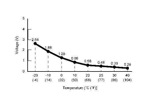
Is the inspection result normal?
YES>>Replace heat pump control unit. Refer to Removal & Installation.
NO>>GO TO 2.
CHECK EVAPORATOR DISCHARGE REFRIGERANT TEMPERATURE SENSOR POWER SUPPLY
-
Power switch OFF.
-
Disconnect evaporator discharge refrigerant temperature sensor connector.
-
Power switch ON.
-
Check voltage between evaporator discharge refrigerant temperature sensor harness connector and ground.
+ - Voltage
(Approx.)Evaporator discharge refrigerant temperature sensor Connector Terminal B104 1 Ground 5 V
Is the inspection result normal?
YES>>GO TO 3.
NO>>GO TO 4.
CHECK EVAPORATOR DISCHARGE REFRIGERANT TEMPERATURE SENSOR
Check evaporator discharge refrigerant temperature sensor. Refer to Component Inspection.
Is the inspection result normal?
YES>>Replace heat pump control unit. Refer to Removal & Installation.
NO>>Replace evaporator discharge refrigerant temperature sensor. Refer to Removal & Installation.
CHECK EVAPORATOR DISCHARGE REFRIGERANT TEMPERATURE SENSOR POWER SUPPLY CIRCUIT FOR SHORT
-
Power switch OFF.
-
Disconnect heat pump control unit connector.
-
Check continuity between evaporator discharge refrigerant temperature sensor harness connector and ground.
Evaporator discharge refrigerant temperature sensor — Continuity Connector Terminal B104 1 Ground Not existed
Is the inspection result normal?
YES>>Replace heat pump control unit. Refer to Removal & Installation.
NO>>Repair harness or connector.
Component Inspection
CHECK EVAPORATOR DISCHARGE REFRIGERANT TEMPERATURE SENSOR
-
Power switch OFF.
-
Remove evaporator discharge refrigerant temperature sensor. Refer to Removal & Installation.
-
Check resistance between evaporator discharge refrigerant temperature sensor harness connector terminals. Refer to applicable table for the normal value.
Terminal Condition Resistance: kΩ Temperature: °C (°F) 1 2 −20 (−4) 15.86 −10 (14) 9.58 0 (32) 6.00 10 (50) 3.89 20 (68) 2.59 25 (77) 2.14 30 (86) 1.78 40 (104) 1.25
Is the inspection result normal?
YES>>INSPECTION END
NO>>Replace evaporator discharge refrigerant temperature sensor. Refer to Removal & Installation.
B2440-15 Evaporator Discharge Refrigerant Temperature Sensor Nissan Ariya
DTC Description
DTC DETECTION LOGIC
| DTC No. | CONSULT screen terms | DTC detection condition | |
|---|---|---|---|
| B2440-15 | Evaporator discharge refrigerant temperature sensor | Diagnosis condition | Power switch ON |
| Signal (Terminal) | Evaporator discharge refrigerant temperature sensor signal | ||
| Threshold | The evaporator discharge refrigerant temperature sensor recognition temperature is too low [less than -60°C (-76°F)] | ||
| Diagnosis delay time | 4 seconds or more | ||
POSSIBLE CAUSE
-
Evaporator discharge refrigerant temperature sensor
-
Heat pomp control unit
-
Harness or connectors (the sensor circuit is open or shorted to battery)
FAIL-SAFE
Electric compressor operation is stopped
DTC CONFIRMATION PROCEDURE
PERFORM DTC CONFIRMATION PROCEDURE
With CONSULT
-
Power switch ON.
-
Select “Self Diagnostic Result” mode of “HEAT PUMP CONTROL” using CONSULT.
Is DTC detected?
YES>>Refer to Diagnosis Procedure.
NO-1>>To check malfunction symptom before repair: Refer to Intermittent Incident.
NO-2>>Confirmation after repair: INSPECTION END
Diagnosis Procedure
CHECK EVAPORATOR DISCHARGE REFRIGERANT TEMPERATURE SENSOR SIGNAL
-
Power switch ON.
-
Check voltage between heat pump control unit harness connector.
Heat pump control unit Voltage Connector Terminal + - M913 11 27
Is the inspection result normal?
YES>>Replace heat pump control unit. Refer to Removal & Installation.
NO>>GO TO 2.
CHECK EVAPORATOR DISCHARGE REFRIGERANT TEMPERATURE SENSOR POWER SUPPLY
-
Power switch OFF.
-
Disconnect evaporator discharge refrigerant temperature sensor connector.
-
Power switch ON.
-
Check voltage between evaporator discharge refrigerant temperature sensor harness connector and ground.
+ - Voltage
(Approx.)Evaporator discharge refrigerant temperature sensor Connector Terminal B104 1 Ground 5 V
Is the inspection result normal?
YES>>GO TO 3.
NO>>GO TO 5.
CHECK EVAPORATOR DISCHARGE REFRIGERANT TEMPERATURE SENSOR GROUND CIRCUIT FOR OPEN
-
Power switch OFF.
-
Disconnect heat pump control unit connector.
-
Check continuity between evaporator discharge refrigerant temperature sensor harness connector and heat pump control unit harness connector.
Evaporator discharge refrigerant temperature sensor Heat pump control unit Continuity Connector Terminal Connector Terminal B104 2 M913 27 Existed
Is the inspection result normal?
YES>>GO TO 4.
NO>>Repair harness or connector.
CHECK EVAPORATOR DISCHARGE REFRIGERANT TEMPERATURE SENSOR
Check evaporator discharge refrigerant temperature sensor. Refer to Component Inspection.
Is the inspection result normal?
YES>>Replace heat pump control unit. Refer to Removal & Installation.
NO>>Replace evaporator discharge refrigerant temperature sensor. Refer to Removal & Installation.
CHECK EVAPORATOR DISCHARGE REFRIGERANT TEMPERATURE SENSOR POWER SUPPLY CIRCUIT FOR OPEN
-
Power switch OFF.
-
Disconnect heat pump control unit connector.
-
Check continuity between evaporator discharge refrigerant temperature sensor harness connector and heat pump control unit harness connector.
Evaporator discharge refrigerant temperature sensor Heat pump control unit Continuity Connector Terminal Connector Terminal B104 1 M913 11 Existed
Is the inspection result normal?
YES>>GO TO 6.
NO>>Repair harness or connector.
CHECK EVAPORATOR DISCHARGE REFRIGERANT TEMPERATURE SENSOR POWER SUPPLY CIRCUIT FOR SHORT
Check voltage between evaporator discharge refrigerant temperature sensor harness connector and ground.
| + | - |
Voltage (Approx.) | |
|---|---|---|---|
| Evaporator discharge refrigerant temperature sensor | |||
| Connector | Terminal | ||
| B104 | 1 | Ground | 0 V |
Is the inspection result normal?
YES>>Replace heat pump control unit. Refer to Removal & Installation.
NO>>Repair harness or connector.
Component Inspection
CHECK EVAPORATOR DISCHARGE REFRIGERANT TEMPERATURE SENSOR
-
Power switch OFF.
-
Remove evaporator discharge refrigerant temperature sensor. Refer to Removal & Installation.
-
Check resistance between evaporator discharge refrigerant temperature sensor harness connector terminals. Refer to applicable table for the normal value.
Terminal Condition Resistance: kΩ Temperature: °C (°F) 1 2 −20 (−4) 15.86 −10 (14) 9.58 0 (32) 6.00 10 (50) 3.89 20 (68) 2.59 25 (77) 2.14 30 (86) 1.78 40 (104) 1.25
Is the inspection result normal?
YES>>INSPECTION END
NO>>Replace evaporator discharge refrigerant temperature sensor. Refer to Removal & Installation.
B2441-11 Condenser Discharge Refrigerant Temperature Sensor Nissan Ariya 2026
DTC Description
DTC DETECTION LOGIC
| DTC No. | CONSULT screen terms | DTC detection condition | |
|---|---|---|---|
| B2441-11 | Condenser discharge refrigerant temperature sensor | Diagnosis condition | Power switch ON |
| Signal (Terminal) | Condenser discharge refrigerant temperature sensor signal | ||
| Threshold | The condenser discharge refrigerant temperature sensor recognition temperature is too high [more than 143°C (289°F)] | ||
| Diagnosis delay time | 4 seconds or more | ||
POSSIBLE CAUSE
-
Condenser discharge refrigerant temperature sensor
-
Heat pomp control unit
-
Harness or connectors (the sensor circuit is shorted to ground)
FAIL-SAFE
Electric compressor operation is stopped
DTC CONFIRMATION PROCEDURE
PERFORM DTC CONFIRMATION PROCEDURE
With CONSULT
-
Power switch ON.
-
Select “Self Diagnostic Result” mode of “HEAT PUMP CONTROL” using CONSULT.
Is DTC detected?
YES>>Refer to Diagnosis Procedure.
NO-1>>To check malfunction symptom before repair: Refer to Intermittent Incident.
NO-2>>Confirmation after repair: INSPECTION END
Diagnosis Procedure
CHECK CONDENSER DISCHARGE REFRIGERANT TEMPERATURE SENSOR SIGNAL
-
Power switch ON.
-
Check voltage between heat pump control unit harness connector.
Heat pump control unit Voltage Connector Terminal + - M913 10 27 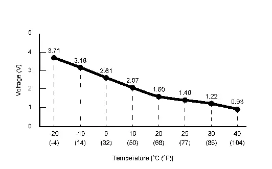
Is the inspection result normal?
YES>>Replace heat pump control unit. Refer to Removal & Installation.
NO>>GO TO 2.
CHECK CONDENSER DISCHARGE REFRIGERANT TEMPERATURE SENSOR POWER SUPPLY
-
Power switch OFF.
-
Disconnect condenser discharge refrigerant temperature sensor connector.
-
Power switch ON.
-
Check voltage between condenser discharge refrigerant temperature sensor harness connector and ground.
+ - Voltage
(Approx.)Condenser discharge refrigerant temperature sensor Connector Terminal B53 1 Ground 5 V
Is the inspection result normal?
YES>>GO TO 3.
NO>>GO TO 4.
CHECK CONDENSER DISCHARGE REFRIGERANT TEMPERATURE SENSOR
Check condenser discharge refrigerant temperature sensor. Refer to Component Inspection.
Is the inspection result normal?
YES>>Replace heat pump control unit. Refer to Removal & Installation.
NO>>Replace condenser discharge refrigerant temperature sensor. Refer to Removal & Installation.
CHECK CONDENSER DISCHARGE REFRIGERANT TEMPERATURE SENSOR POWER SUPPLY CIRCUIT FOR SHORT
-
Power switch OFF.
-
Disconnect heat pump control unit connector.
-
Check continuity between condenser discharge refrigerant temperature sensor harness connector and ground.
Condenser discharge refrigerant temperature sensor — Continuity Connector Terminal B53 1 Ground Not existed
Is the inspection result normal?
YES>>Replace heat pump control unit. Refer to Removal & Installation.
NO>>Repair harness or connector.
Component Inspection
CHECK CONDENSER DISCHARGE REFRIGERANT TEMPERATURE SENSOR
-
Power switch OFF.
-
Remove condenser discharge refrigerant temperature sensor. Refer to Removal & Installation.
-
Check resistance between condenser discharge refrigerant temperature sensor harness connector terminals. Refer to applicable table for the normal value.
Terminal Condition Resistance: kΩ Temperature: °C (°F) 1 2 −20 (−4) 15.86 −10 (14) 9.58 0 (32) 6.00 10 (50) 3.89 20 (68) 2.59 25 (77) 2.14 30 (86) 1.78 40 (104) 1.25
Is the inspection result normal?
YES>>INSPECTION END
NO>>Replace condenser discharge refrigerant temperature sensor. Refer to Removal & Installation.
B2441-15 Condenser Discharge Refrigerant Temperature Sensor Nissan Ariya SUV
DTC Description
DTC DETECTION LOGIC
| DTC No. | CONSULT screen terms | DTC detection condition | |
|---|---|---|---|
| B2441-15 | Condenser discharge refrigerant temperature sensor | Diagnosis condition | Power switch ON |
| Signal (Terminal) | Condenser discharge refrigerant temperature sensor signal | ||
| Threshold | The condenser discharge refrigerant temperature sensor recognition temperature is too low [less than -64°C (-147°F)] | ||
| Diagnosis delay time | 4 seconds or more | ||
POSSIBLE CAUSE
-
Condenser discharge refrigerant temperature sensor
-
Heat pomp control unit
-
Harness or connectors (the sensor circuit is open or shorted to battery)
FAIL-SAFE
Electric compressor operation is stopped
DTC CONFIRMATION PROCEDURE
PERFORM DTC CONFIRMATION PROCEDURE
With CONSULT
-
Power switch ON.
-
Select “Self Diagnostic Result” mode of “HEAT PUMP CONTROL” using CONSULT.
Is DTC detected?
YES>>Refer to Diagnosis Procedure.
NO-1>>To check malfunction symptom before repair: Refer to Intermittent Incident.
NO-2>>Confirmation after repair: INSPECTION END
Diagnosis Procedure
CHECK CONDENSER DISCHARGE REFRIGERANT TEMPERATURE SENSOR SIGNAL
-
Power switch ON.
-
Check voltage between heat pump control unit harness connector.
Heat pump control unit Voltage Connector Terminal + - M913 10 27
Is the inspection result normal?
YES>>Replace heat pump control unit. Refer to Removal & Installation.
NO>>GO TO 2.
CHECK CONDENSER DISCHARGE REFRIGERANT TEMPERATURE SENSOR POWER SUPPLY
-
Power switch OFF.
-
Disconnect condenser discharge refrigerant temperature sensor connector.
-
Power switch ON.
-
Check voltage between condenser discharge refrigerant temperature sensor harness connector and ground.
+ - Voltage
(Approx.)Condenser discharge refrigerant temperature sensor Connector Terminal B53 1 Ground 5 V
Is the inspection result normal?
YES>>GO TO 3.
NO>>GO TO 5.
CHECK CONDENSER DISCHARGE REFRIGERANT TEMPERATURE SENSOR GROUND CIRCUIT FOR OPEN
-
Power switch OFF.
-
Disconnect heat pump control unit connector.
-
Check continuity between condenser discharge refrigerant temperature sensor harness connector and heat pump control unit harness connector.
Condenser discharge refrigerant temperature sensor Heat pump control unit Continuity Connector Terminal Connector Terminal B53 2 M913 27 Existed
Is the inspection result normal?
YES>>GO TO 4.
NO>>Repair harness or connector.
CHECK CONDENSER DISCHARGE REFRIGERANT TEMPERATURE SENSOR
Check condenser discharge refrigerant temperature sensor. Refer to Component Inspection.
Is the inspection result normal?
YES>>Replace heat pump control unit. Refer to Removal & Installation.
NO>>Replace condenser discharge refrigerant temperature sensor. Refer to Removal & Installation.
CHECK CONDENSER DISCHARGE REFRIGERANT TEMPERATURE SENSOR POWER SUPPLY CIRCUIT FOR OPEN
-
Power switch OFF.
-
Disconnect heat pump control unit connector.
-
Check continuity between condenser discharge refrigerant temperature sensor harness connector and heat pump control unit harness connector.
Condenser discharge refrigerant temperature sensor Heat pump control unit Continuity Connector Terminal Connector Terminal B53 1 M913 27 Existed
Is the inspection result normal?
YES>>GO TO 6.
NO>>Repair harness or connector.
CHECK CONDENSER DISCHARGE REFRIGERANT TEMPERATURE SENSOR POWER SUPPLY CIRCUIT FOR SHORT
Check voltage between condenser discharge refrigerant temperature sensor harness connector and ground.
| + | - |
Voltage (Approx.) | |
|---|---|---|---|
| Condenser discharge refrigerant temperature sensor | |||
| Connector | Terminal | ||
| B53 | 1 | Ground | 0 V |
Is the inspection result normal?
YES>>Replace heat pump control unit. Refer to Removal & Installation.
NO>>Repair harness or connector.
Component Inspection
CHECK CONDENSER DISCHARGE REFRIGERANT TEMPERATURE SENSOR
-
Power switch OFF.
-
Remove condenser discharge refrigerant temperature sensor. Refer to Removal & Installation.
-
Check resistance between condenser discharge refrigerant temperature sensor harness connector terminals. Refer to applicable table for the normal value.
Terminal Condition Resistance: kΩ Temperature: °C (°F) 1 2 −20 (−4) 15.86 −10 (14) 9.58 0 (32) 6.00 10 (50) 3.89 20 (68) 2.59 25 (77) 2.14 30 (86) 1.78 40 (104) 1.25
Is the inspection result normal?
YES>>INSPECTION END
NO>>Replace condenser discharge refrigerant temperature sensor. Refer to Removal & Installation.
B2442-11 Compressor Discharge Refrigerant Temperature Sensor Nissan Ariya 1st generation
DTC Description
DTC DETECTION LOGIC
| DTC No. | CONSULT screen terms | DTC detection condition | |
|---|---|---|---|
| B2442-11 | Compressor discharge refrigerant temperature sensor | Diagnosis condition | Power switch ON |
| Signal (Terminal) | Compressor discharge refrigerant temperature sensor signal | ||
| Threshold | The compressor discharge refrigerant temperature sensor recognition temperature is too high [more than 283°C (541°F)] | ||
| Diagnosis delay time | 4 seconds or more | ||
POSSIBLE CAUSE
-
Compressor discharge refrigerant temperature sensor
-
Heat pomp control unit
-
Harness or connectors (the sensor circuit is shorted to ground)
FAIL-SAFE
Electric compressor operation is stopped
DTC CONFIRMATION PROCEDURE
PERFORM DTC CONFIRMATION PROCEDURE
With CONSULT
-
Power switch ON.
-
Select “Self Diagnostic Result” mode of “HEAT PUMP CONTROL” using CONSULT.
Is DTC detected?
YES>>Refer to Diagnosis Procedure.
NO-1>>To check malfunction symptom before repair: Refer to Intermittent Incident.
NO-2>>Confirmation after repair: INSPECTION END
Diagnosis Procedure
CHECK COMPRESSOR DISCHARGE REFRIGERANT TEMPERATURE SENSOR SIGNAL
-
Power switch ON.
-
Check voltage between heat pump control unit harness connector.
Heat pump control unit Voltage Connector Terminal + - M913 8 27 
Is the inspection result normal?
YES>>Replace heat pump control unit. Refer to Removal & Installation.
NO>>GO TO 2.
CHECK COMPRESSOR DISCHARGE REFRIGERANT TEMPERATURE SENSOR POWER SUPPLY
-
Power switch OFF.
-
Disconnect compressor discharge refrigerant temperature sensor connector.
-
Power switch ON.
-
Check voltage between compressor discharge refrigerant temperature sensor harness connector and ground.
+ - Voltage
(Approx.)Compressor discharge refrigerant temperature sensor Connector Terminal M320 1 Ground 5 V
Is the inspection result normal?
YES>>GO TO 3.
NO>>GO TO 4.
CHECK COMPRESSOR DISCHARGE REFRIGERANT TEMPERATURE SENSOR
Check compressor discharge refrigerant temperature sensor. Refer to Component Inspection.
Is the inspection result normal?
YES>>Replace heat pump control unit. Refer to Removal & Installation.
NO>>Replace compressor discharge refrigerant temperature sensor. Refer to Removal & Installation.
CHECK COMPRESSOR DISCHARGE REFRIGERANT TEMPERATURE SENSOR POWER SUPPLY CIRCUIT FOR SHORT
-
Power switch OFF.
-
Disconnect heat pump control unit connector.
-
Check continuity between compressor discharge refrigerant temperature sensor harness connector and ground.
Compressor discharge refrigerant temperature sensor — Continuity Connector Terminal M320 1 Ground Not existed
Is the inspection result normal?
YES>>Replace heat pump control unit. Refer to Removal & Installation.
NO>>Repair harness or connector.
Component Inspection
CHECK COMPRESSOR DISCHARGE REFRIGERANT TEMPERATURE SENSOR
-
Power switch OFF.
-
Remove compressor discharge refrigerant temperature sensor. Refer to Removal & Installation.
-
Check resistance between compressor discharge refrigerant temperature sensor harness connector terminals. Refer to applicable table for the normal value.
Terminal Condition Resistance: kΩ Temperature: °C (°F) 1 2 0 (32) 317.5 10 (50) 192.8 20 (68) 120.4 25 (77) 77.1 30 (86) 50.7 40 (104) 23.4 80 (176) 8.4 100 (212) 6.2
Is the inspection result normal?
YES>>INSPECTION END
NO>>Replace compressor discharge refrigerant temperature sensor. Refer to Removal & Installation.
B2442-15 Compressor Discharge Refrigerant Temperature Sensor Nissan Ariya 1st generation
DTC Description
DTC DETECTION LOGIC
| DTC No. | CONSULT screen terms | DTC detection condition | |
|---|---|---|---|
| B2442-15 | Compressor discharge refrigerant temperature sensor | Diagnosis condition | Power switch ON |
| Signal (Terminal) | Compressor discharge refrigerant temperature sensor signal | ||
| Threshold | The compressor discharge refrigerant temperature sensor recognition temperature is too low [less than -68°C (-154°F)] | ||
| Diagnosis delay time | 4 seconds or more | ||
POSSIBLE CAUSE
-
Compressor discharge refrigerant temperature sensor
-
Heat pomp control unit
-
Harness or connectors (the sensor circuit is open or shorted to battery)
FAIL-SAFE
Electric compressor operation is stopped
DTC CONFIRMATION PROCEDURE
PERFORM DTC CONFIRMATION PROCEDURE
With CONSULT
-
Power switch ON.
-
Select “Self Diagnostic Result” mode of “HEAT PUMP CONTROL” using CONSULT.
Is DTC detected?
YES>>Refer to Diagnosis Procedure.
NO-1>>To check malfunction symptom before repair: Refer to Intermittent Incident.
NO-2>>Confirmation after repair: INSPECTION END
Diagnosis Procedure
CHECK COMPRESSOR DISCHARGE REFRIGERANT TEMPERATURE SENSOR SIGNAL
-
Power switch ON.
-
Check voltage between heat pump control unit harness connector.
Heat pump control unit Voltage Connector Terminal + - M913 8 27
Is the inspection result normal?
YES>>Replace heat pump control unit. Refer to Removal & Installation.
NO>>GO TO 2.
CHECK COMPRESSOR DISCHARGE REFRIGERANT TEMPERATURE SENSOR POWER SUPPLY
-
Power switch OFF.
-
Disconnect compressor discharge refrigerant temperature sensor connector.
-
Power switch ON.
-
Check voltage between compressor discharge refrigerant temperature sensor harness connector and ground.
+ - Voltage
(Approx.)Compressor discharge refrigerant temperature sensor Connector Terminal M320 1 Ground 5 V
Is the inspection result normal?
YES>>GO TO 3.
NO>>GO TO 5.
CHECK COMPRESSOR DISCHARGE REFRIGERANT TEMPERATURE SENSOR GROUND CIRCUIT FOR OPEN
-
Power switch OFF.
-
Disconnect heat pump control unit connector.
-
Check continuity between compressor discharge refrigerant temperature sensor harness connector and heat pump control unit harness connector.
Compressor discharge refrigerant temperature sensor Heat pump control unit Continuity Connector Terminal Connector Terminal M320 2 M913 27 Existed
Is the inspection result normal?
YES>>GO TO 4.
NO>>Repair harness or connector.
CHECK COMPRESSOR DISCHARGE REFRIGERANT TEMPERATURE SENSOR
Check compressor discharge refrigerant temperature sensor. Refer to Component Inspection.
Is the inspection result normal?
YES>>Replace heat pump control unit. Refer to Removal & Installation.
NO>>Replace compressor discharge refrigerant temperature sensor. Refer to Removal & Installation.
CHECK COMPRESSOR DISCHARGE REFRIGERANT TEMPERATURE SENSOR POWER SUPPLY CIRCUIT FOR OPEN
-
Power switch OFF.
-
Disconnect heat pump control unit connector.
-
Check continuity between compressor discharge refrigerant temperature sensor harness connector and heat pump control unit harness connector.
Compressor discharge refrigerant temperature sensor Heat pump control unit Continuity Connector Terminal Connector Terminal M320 1 M913 8 Existed
Is the inspection result normal?
YES>>GO TO 6.
NO>>Repair harness or connector.
CHECK COMPRESSOR DISCHARGE REFRIGERANT TEMPERATURE SENSOR POWER SUPPLY CIRCUIT FOR SHORT
Check voltage between compressor discharge refrigerant temperature sensor harness connector and ground.
| + | - |
Voltage (Approx.) | |
|---|---|---|---|
| Compressor discharge refrigerant temperature sensor | |||
| Connector | Terminal | ||
| M320 | 1 | Ground | 0 V |
Is the inspection result normal?
YES>>Replace heat pump control unit. Refer to Removal & Installation.
NO>>Repair harness or connector.
Component Inspection
CHECK COMPRESSOR DISCHARGE REFRIGERANT TEMPERATURE SENSOR
-
Power switch OFF.
-
Remove compressor discharge refrigerant temperature sensor. Refer to Removal & Installation.
-
Check resistance between compressor discharge refrigerant temperature sensor harness connector terminals. Refer to applicable table for the normal value.
Terminal Condition Resistance: kΩ Temperature: °C (°F) 1 2 0 (32) 317.5 10 (50) 192.8 20 (68) 120.4 25 (77) 77.1 30 (86) 50.7 40 (104) 23.4 80 (176) 8.4 100 (212) 6.2
Is the inspection result normal?
YES>>INSPECTION END
NO>>Replace compressor discharge refrigerant temperature sensor. Refer to Removal & Installation.
B2443-11 Inner Condenser Discharge Refrigerant Temperature Sensor Nissan Ariya 2023
DTC Description
DTC DETECTION LOGIC
| DTC No. | CONSULT screen terms | DTC detection condition | |
|---|---|---|---|
| B2443-11 | Inner condenser discharge refrigerant temperature sensor | Diagnosis condition | Power switch ON |
| Signal (Terminal) | Inner condenser discharge refrigerant temperature sensor signal | ||
| Threshold | The inner condenser discharge refrigerant temperature sensor recognition temperature is too high [more than 222°C (431°F)] | ||
| Diagnosis delay time | 4 seconds or more | ||
POSSIBLE CAUSE
-
Inner condenser discharge refrigerant temperature sensor
-
Heat pomp control unit
-
Harness or connectors (the sensor circuit is shorted to ground)
FAIL-SAFE
Operate only cooler
DTC CONFIRMATION PROCEDURE
PERFORM DTC CONFIRMATION PROCEDURE
With CONSULT
-
Power switch ON.
-
Select “Self Diagnostic Result” mode of “HEAT PUMP CONTROL” using CONSULT.
Is DTC detected?
YES>>Refer to Diagnosis Procedure.
NO-1>>To check malfunction symptom before repair: Refer to Intermittent Incident.
NO-2>>Confirmation after repair: INSPECTION END
Diagnosis Procedure
CHECK INNER CONDENSER DISCHARGE REFRIGERANT TEMPERATURE SENSOR SIGNAL
-
Power switch ON.
-
Check voltage between heat pump control unit harness connector.
Heat pump control unit Voltage Connector Terminal + - M913 9 27 
Is the inspection result normal?
YES>>Replace heat pump control unit. Refer to Removal & Installation.
NO>>GO TO 2.
CHECK INNER CONDENSER DISCHARGE REFRIGERANT TEMPERATURE SENSOR POWER SUPPLY
-
Power switch OFF.
-
Disconnect inner condenser discharge refrigerant temperature sensor connector.
-
Power switch ON.
-
Check voltage between inner condenser discharge refrigerant temperature sensor harness connector and ground.
+ - Voltage
(Approx.)Inner condenser discharge refrigerant temperature sensor Connector Terminal M319 1 Ground 5 V
Is the inspection result normal?
YES>>GO TO 3.
NO>>GO TO 4.
CHECK INNER CONDENSER DISCHARGE REFRIGERANT TEMPERATURE SENSOR
Check inner condenser discharge refrigerant temperature sensor. Refer to Component Inspection.
Is the inspection result normal?
YES>>Replace heat pump control unit. Refer to Removal & Installation.
NO>>Replace inner condenser discharge refrigerant temperature sensor. Refer to Removal & Installation.
CHECK INNER CONDENSER DISCHARGE REFRIGERANT TEMPERATURE SENSOR POWER SUPPLY CIRCUIT FOR SHORT
-
Power switch OFF.
-
Disconnect heat pump control unit connector.
-
Check continuity between inner condenser discharge refrigerant temperature sensor harness connector and ground.
Inner condenser discharge refrigerant temperature sensor — Continuity Connector Terminal M319 1 Ground Not existed
Is the inspection result normal?
YES>>Replace heat pump control unit. Refer to Removal & Installation.
NO>>Repair harness or connector.
Component Inspection
CHECK INNER CONDENSER DISCHARGE REFRIGERANT TEMPERATURE SENSOR
-
Power switch OFF.
-
Remove inner condenser discharge refrigerant temperature sensor. Refer to Removal & Installation.
-
Check resistance between inner condenser discharge refrigerant temperature sensor harness connector terminals. Refer to applicable table for the normal value.
Terminal Condition Resistance: kΩ Temperature: °C (°F) 1 2 0 (32) 317.5 10 (50) 192.8 20 (68) 120.4 25 (77) 77.1 30 (86) 50.7 40 (104) 23.4 80 (176) 8.4 100 (212) 6.2
Is the inspection result normal?
YES>>INSPECTION END
NO>>Replace inner condenser discharge refrigerant temperature sensor. Refer to Removal & Installation.
B2443-15 Inner Condenser Discharge Refrigerant Temperature Sensor Nissan Ariya 2026
DTC Description
DTC DETECTION LOGIC
| DTC No. | CONSULT screen terms | DTC detection condition | |
|---|---|---|---|
| B2443-15 | Inner condenser discharge refrigerant temperature sensor | Diagnosis condition | Power switch ON |
| Signal (Terminal) | Inner condenser discharge refrigerant temperature sensor signal | ||
| Threshold | The Inner condenser discharge refrigerant temperature sensor recognition temperature is too low [less than -69°C (-156°F)] | ||
| Diagnosis delay time | 4 seconds or more | ||
POSSIBLE CAUSE
-
Inner condenser discharge refrigerant temperature sensor
-
Heat pomp control unit
-
Harness or connectors (the sensor circuit is open or shorted to battery)
FAIL-SAFE
Operate only cooler
DTC CONFIRMATION PROCEDURE
PERFORM DTC CONFIRMATION PROCEDURE
With CONSULT
-
Power switch ON.
-
Select “Self Diagnostic Result” mode of “HEAT PUMP CONTROL” using CONSULT.
Is DTC detected?
YES>>Refer to Diagnosis Procedure.
NO-1>>To check malfunction symptom before repair: Refer to Intermittent Incident.
NO-2>>Confirmation after repair: INSPECTION END
Diagnosis Procedure
CHECK INNER CONDENSER DISCHARGE REFRIGERANT TEMPERATURE SENSOR SIGNAL
-
Power switch ON.
-
Check voltage between heat pump control unit harness connector.
Heat pump control unit Voltage Connector Terminal + - M913 9 27
Is the inspection result normal?
YES>>Replace heat pump control unit. Refer to Removal & Installation.
NO>>GO TO 2.
CHECK INNER CONDENSER DISCHARGE REFRIGERANT TEMPERATURE SENSOR POWER SUPPLY
-
Power switch OFF.
-
Disconnect inner condenser discharge refrigerant temperature sensor connector.
-
Power switch ON.
-
Check voltage between inner condenser discharge refrigerant temperature sensor harness connector and ground.
+ - Voltage
(Approx.)Inner condenser discharge refrigerant temperature sensor Connector Terminal M319 1 Ground 5 V
Is the inspection result normal?
YES>>GO TO 3.
NO>>GO TO 5.
CHECK INNER CONDENSER DISCHARGE REFRIGERANT TEMPERATURE SENSOR GROUND CIRCUIT FOR OPEN
-
Power switch OFF.
-
Disconnect heat pump control unit connector.
-
Check continuity between inner condenser discharge refrigerant temperature sensor harness connector and heat pump control unit harness connector.
Inner condenser discharge refrigerant temperature sensor Heat pump control unit Continuity Connector Terminal Connector Terminal M319 2 M913 27 Existed
Is the inspection result normal?
YES>>GO TO 4.
NO>>Repair harness or connector.
CHECK INNER CONDENSER DISCHARGE REFRIGERANT TEMPERATURE SENSOR
Check inner condenser discharge refrigerant temperature sensor. Refer to Component Inspection.
Is the inspection result normal?
YES>>Replace heat pump control unit. Refer to Removal & Installation.
NO>>Replace inner condenser discharge refrigerant temperature sensor. Refer to Component Inspection.
CHECK INNER CONDENSER DISCHARGE REFRIGERANT TEMPERATURE SENSOR POWER SUPPLY CIRCUIT FOR OPEN
-
Power switch OFF.
-
Disconnect heat pump control unit connector.
-
Check continuity between inner condenser discharge refrigerant temperature sensor harness connector and heat pump control unit harness connector.
Inner condenser discharge refrigerant temperature sensor Heat pump control unit Continuity Connector Terminal Connector Terminal M319 1 M913 9 Existed
Is the inspection result normal?
YES>>GO TO 6.
NO>>Repair harness or connector.
CHECK INNER CONDENSER DISCHARGE REFRIGERANT TEMPERATURE SENSOR POWER SUPPLY CIRCUIT FOR SHORT
Check voltage between inner condenser discharge refrigerant temperature sensor harness connector and ground.
| + | - |
Voltage (Approx.) | |
|---|---|---|---|
| Inner condenser discharge refrigerant temperature sensor | |||
| Connector | Terminal | ||
| M319 | 1 | Ground | 0 V |
Is the inspection result normal?
YES>>Replace heat pump control unit. Refer to Removal & Installation.
NO>>Repair harness or connector.
Component Inspection
CHECK INNER CONDENSER DISCHARGE REFRIGERANT TEMPERATURE SENSOR
-
Power switch OFF.
-
Remove inner condenser discharge refrigerant temperature sensor. Refer to Removal & Installation.
-
Check resistance between inner condenser discharge refrigerant temperature sensor harness connector terminals. Refer to applicable table for the normal value.
Terminal Condition Resistance: kΩ Temperature: °C (°F) 1 2 0 (32) 317.5 10 (50) 192.8 20 (68) 120.4 25 (77) 77.1 30 (86) 50.7 40 (104) 23.4 80 (176) 8.4 100 (212) 6.2
Is the inspection result normal?
YES>>INSPECTION END
NO>>Replace inner condenser discharge refrigerant temperature sensor. Refer to Removal & Installation.
B2446-23 Refrigerant Leak Nissan Ariya 1st generation
DTC Description
DTC DETECTION LOGIC
| DTC No. | CONSULT screen terms | DTC detection condition | |
|---|---|---|---|
| B2446–23 | Refrigerant gas leak | Diagnosis condition | Power switch ON |
| Signal (terminal) | — | ||
| Threshold | Refrigerant is leaking or not in | ||
| Diagnosis delay time | — | ||
POSSIBLE CAUSE
-
Refrigerant is leaking or not in
-
Refrigerant pressure sensor
-
VCM
-
Harness or connectors (refrigerant pressure sensor and VCM circuit is open or shorted)
FAIL-SAFE
Electric compressor operation is stopped
DTC CONFIRMATION PROCEDURE
PERFORM DTC CONFIRMATION PROCEDURE
With CONSULT
-
Power switch OFF.
-
Set the Nissan Ariya vehicle to READY.
-
Operate the air conditioning system.
-
Set the temperature to full cold.
-
Select “Self Diagnostic Result” mode of “HEAT PUMP CONTROL” using CONSULT.
Is DTC detected?
YES>>Refer to Diagnosis Procedure.
NO-1>>To check malfunction symptom before repair: Refer to Intermittent Incident.
NO-2>>Confirmation after repair: INSPECTION END
Diagnosis Procedure
CHECK REFRIGERANT PRESSURE SENSOR SYSTEM
Check refrigerant pressure sensor system. Refer to Diagnosis Procedure.
Is the inspection result normal?
YES>>GO TO 2.
NO>>Repair or replace malfunctioning part.
CHECK REFRIGERANT LEAK
Check refrigerant leak. Refer to Leak Test.
Is the inspection result normal?
YES>>INSPECTION END
NO>>Repair or replace malfunctioning part.
P1c00-44 Heat Pump Control Unit Nissan Ariya first Gen
DTC Description
DTC DETECTION LOGIC
| DTC No. | CONSULT screen terms | DTC detection condition | |
|---|---|---|---|
| P1C00–44 | Heat pump control unit | Diagnosis condition | Power switch ON |
| Signal (terminal) | — | ||
| Threshold | When the data error in the RAM area of ECU is detected | ||
| Diagnosis delay time | 2 seconds or more | ||
POSSIBLE CAUSE
Heat pump control unit
FAIL-SAFE
Electric compressor operation is stopped
DTC CONFIRMATION PROCEDURE
PERFORM DTC CONFIRMATION PROCEDURE
With CONSULT
-
Power switch ON.
-
Select “Self Diagnostic Result” mode of “HEAT PUMP CONTROL” using CONSULT.
Is DTC detected?
YES>>Refer to Diagnosis Procedure.
NO-1>>To check malfunction symptom before repair: Refer to Intermittent Incident.
NO-2>>Confirmation after repair: INSPECTION END
Diagnosis Procedure
REPLACE HEAT PUMP CONTROL UNIT
Replace heat pump control unit. Refer to Removal & Installation.
>>
INSPECTION END
P1c00-46 Heat Pump Control Unit Nissan Ariya 2026
DTC Description
DTC DETECTION LOGIC
| DTC No. | CONSULT screen terms | DTC detection condition | |
|---|---|---|---|
| P1C00–46 | Heat pump control unit | Diagnosis condition | Power switch ON |
| Signal (terminal) | — | ||
| Threshold | When the data error in the EEPROM memory function of ECU is detected | ||
| Diagnosis delay time | 2 seconds or more | ||
POSSIBLE CAUSE
Heat pump control unit
FAIL-SAFE
Electric compressor operation is stopped
DTC CONFIRMATION PROCEDURE
PERFORM DTC CONFIRMATION PROCEDURE
With CONSULT
-
Power switch ON.
-
Select “Self Diagnostic Result” mode of “HEAT PUMP CONTROL” using CONSULT.
Is DTC detected?
YES>>Refer to Diagnosis Procedure.
NO-1>>To check malfunction symptom before repair: Refer to Intermittent Incident.
NO-2>>Confirmation after repair: INSPECTION END
Diagnosis Procedure
REPLACE HEAT PUMP CONTROL UNIT
Replace heat pump control unit. Refer to Removal & Installation.
>>
INSPECTION END
P1c00-47 Heat Pump Control Unit Nissan Ariya SUV
DTC Description
DTC DETECTION LOGIC
| DTC No. | CONSULT screen terms | DTC detection condition | |
|---|---|---|---|
| P1C00–47 | Heat pump control unit | Diagnosis condition | Power switch ON |
| Signal (terminal) | — | ||
| Threshold | When the Watchdog timer detects an error (control of the entire ECU is not operating normally) | ||
| Diagnosis delay time | 2 seconds or more | ||
POSSIBLE CAUSE
Heat pump control unit
FAIL-SAFE
Electric compressor operation is stopped
DTC CONFIRMATION PROCEDURE
PERFORM DTC CONFIRMATION PROCEDURE
With CONSULT
-
Power switch ON.
-
Select “Self Diagnostic Result” mode of “HEAT PUMP CONTROL” using CONSULT.
Is DTC detected?
YES>>Refer to Diagnosis Procedure.
NO-1>>To check malfunction symptom before repair: Refer to Intermittent Incident.
NO-2>>Confirmation after repair: INSPECTION END
Diagnosis Procedure
REPLACE HEAT PUMP CONTROL UNIT
Replace heat pump control unit. Refer to Removal & Installation.
>>
INSPECTION END
P1c00-49 Heat Pump Control Unit Nissan Ariya: FE0
DTC Description
DTC DETECTION LOGIC
| DTC No. | CONSULT screen terms | DTC detection condition | |
|---|---|---|---|
| P1C00–49 | Heat pump control unit | Diagnosis condition | Power switch ON |
| Signal (terminal) | — | ||
| Threshold | When an abnormality is detected in the IC for CAN communication | ||
| Diagnosis delay time | 2 seconds or more | ||
POSSIBLE CAUSE
Heat pump control unit
FAIL-SAFE
Electric compressor operation is stopped
DTC CONFIRMATION PROCEDURE
PERFORM DTC CONFIRMATION PROCEDURE
With CONSULT
-
Power switch ON.
-
Select “Self Diagnostic Result” mode of “HEAT PUMP CONTROL” using CONSULT.
Is DTC detected?
YES>>Refer to Diagnosis Procedure.
NO-1>>To check malfunction symptom before repair: Refer to Intermittent Incident.
NO-2>>Confirmation after repair: INSPECTION END
Diagnosis Procedure
REPLACE HEAT PUMP CONTROL UNIT
Replace heat pump control unit. Refer to Removal & Installation.
>>
INSPECTION END
P1c01-71 High Pressure Refrigerant Channel Switching Valve Nissan Ariya SUV
DTC Description
DTC DETECTION LOGIC
| DTC No. | CONSULT screen terms | DTC detection condition | |
|---|---|---|---|
| P1C01-71 | High pressure refrigerant channel switching valve | Diagnosis condition | Power switch ON |
| Signal (Terminal) | High pressure refrigerant channel switching valve control signal circuit | ||
| Threshold | When the control signal error of high pressure refrigerant channel switching valve is detected | ||
| Diagnosis delay time | 4 seconds or more | ||
POSSIBLE CAUSE
-
High pressure refrigerant channel switching valve
-
Heat pump control unit
-
Harness or connectors (switching valve circuit is open or shorted)
FAIL-SAFE
Electric compressor operation is stopped
DTC CONFIRMATION PROCEDURE
PERFORM DTC CONFIRMATION PROCEDURE
With CONSULT
-
Power switch ON.
-
Select “Self Diagnostic Result” mode of “HEAT PUMP CONTROL” using CONSULT.
Is DTC detected?
YES>>Refer to Diagnosis Procedure.
NO-1>>To check malfunction symptom before repair: Refer to Intermittent Incident.
NO-2>>Confirmation after repair: INSPECTION END
Diagnosis Procedure
CHECK HIGH PRESSURE REFRIGERANT CHANNEL SWITCHING VALVE POWER SUPPLY
-
Power switch OFF.
-
Disconnect high pressure refrigerant channel switching valve connector.
-
Power switch ON.
-
Check voltage between high pressure refrigerant channel switching valve harness connector and ground.
| + | - | Voltage | |
|---|---|---|---|
| High pressure refrigerant channel switching valve | |||
| Connector | Terminal | ||
| B51 | 1 | Ground | Battery voltage |
Is the inspection result normal?
YES>>GO TO 2.
NO>>Repair the high pressure refrigerant channel switching valve power supply circuit.
CHECK HIGH PRESSURE REFRIGERANT CHANNEL SWITCHING VALVE CONTROL CIRCUIT FOR OPEN
-
Power switch OFF.
-
Disconnect heat pump control unit connector.
-
Check continuity between high pressure refrigerant channel switching valve harness connector and heat pump control unit harness connector.
High pressure refrigerant channel switching valve Heat pump control unit Continuity Connector Terminal Connector Terminal B51 2 M913 5 Existed
Is the inspection result normal?
YES>>GO TO 3.
NO>>Repair harness or connector.
CHECK HIGH PRESSURE REFRIGERANT CHANNEL SWITCHING VALVE CONTROL CIRCUIT FOR SHORT
-
Check continuity between high pressure refrigerant channel switching valve harness connector and ground.
High pressure refrigerant channel switching valve — Continuity Connector Terminal B51 2 Ground Not existed -
Check voltage between high pressure refrigerant channel switching valve harness connector and ground.
+ - Voltage
(Approx.)High pressure refrigerant channel switching valve Connector Terminal B51 2 Ground 0 V
Is the inspection result normal?
YES>>GO TO 4.
NO>>Repair harness or connector.
CHECK HIGH PRESSURE REFRIGERANT CHANNEL SWITCHING VALVE
Check high pressure refrigerant channel switching valve. Refer to Component Inspection.
Is the inspection result normal?
YES>>Replace heat pump control unit. Refer to Removal & Installation.
NO>>Replace high pressure refrigerant channel switching valve. Refer to Removal & Installation.
Component Inspection
CHECK HIGH PRESSURE REFRIGERANT CHANNEL SWITCHING VALVE
-
Power switch OFF.
-
Disconnect high pressure refrigerant channel switching valve connector.
-
Check resistance between high pressure refrigerant channel switching valve terminals. Refer to applicable table for the normal value.
Terminal Resistance (Ω)
(Approx.)1 2 13
[Temperature condition: 20°C (68°F)]
Is the inspection result normal?
YES>>INSPECTION END
NO>>Replace high pressure refrigerant channel switching valve. Refer to Removal & Installation.
P1c02-71 Low Pressure Refrigerant Channel Switching Valve Nissan Ariya: FE0
DTC Description
DTC DETECTION LOGIC
| DTC No. | CONSULT screen terms | DTC detection condition | |
|---|---|---|---|
| P1C02-71 | Low pressure refrigerant channel switching valve | Diagnosis condition | Power switch ON |
| Signal (Terminal) | Low pressure refrigerant channel switching valve control signal circuit | ||
| Threshold | When the control signal error of low pressure refrigerant channel switching valve is detected | ||
| Diagnosis delay time | 4 seconds or more | ||
POSSIBLE CAUSE
-
Low pressure refrigerant channel switching valve
-
Heat pump control unit
-
Harness or connectors (switching valve circuit is open or shorted)
FAIL-SAFE
Electric compressor operation is stopped
DTC CONFIRMATION PROCEDURE
PERFORM DTC CONFIRMATION PROCEDURE
With CONSULT
-
Power switch ON.
-
Select “Self Diagnostic Result” mode of “HEAT PUMP CONTROL” using CONSULT.
Is DTC detected?
YES>>Refer to Diagnosis Procedure.
NO-1>>To check malfunction symptom before repair: Refer to Intermittent Incident.
NO-2>>Confirmation after repair: INSPECTION END
Diagnosis Procedure
CHECK LOW PRESSURE REFRIGERANT CHANNEL SWITCHING VALVE POWER SUPPLY
-
Power switch OFF.
-
Disconnect low pressure refrigerant channel switching valve connector.
-
Power switch ON.
-
Check voltage between low pressure refrigerant channel switching valve harness connector and ground.
| + | - | Voltage | |
|---|---|---|---|
| Low pressure refrigerant channel switching valve | |||
| Connector | Terminal | ||
| B129 | 1 | Ground | Battery voltage |
Is the inspection result normal?
YES>>GO TO 2.
NO>>Repair the low pressure refrigerant channel switching valve power supply circuit.
CHECK LOW PRESSURE REFRIGERANT CHANNEL SWITCHING VALVE CONTROL CIRCUIT FOR OPEN
-
Power switch OFF.
-
Disconnect heat pump control unit connector.
-
Check continuity between low pressure refrigerant channel switching valve harness connector and heat pump control unit harness connector.
Low pressure refrigerant channel switching valve Heat pump control unit Continuity Connector Terminal Connector Terminal B129 2 M913 6 Existed
Is the inspection result normal?
YES>>GO TO 3.
NO>>Repair harness or connector.
CHECK LOW PRESSURE REFRIGERANT CHANNEL SWITCHING VALVE CONTROL CIRCUIT FOR SHORT
-
Check continuity between low pressure refrigerant channel switching valve harness connector and ground.
Low pressure refrigerant channel switching valve — Continuity Connector Terminal B129 2 Ground Not existed -
Check voltage between low pressure refrigerant channel switching valve harness connector and ground.
+ - Voltage
(Approx.)Low pressure refrigerant channel switching valve Connector Terminal B129 2 Ground 0 V
Is the inspection result normal?
YES>>GO TO 4.
NO>>Repair harness or connector.
CHECK LOW PRESSURE REFRIGERANT CHANNEL SWITCHING VALVE
Check low pressure refrigerant channel switching valve. Refer to Component Inspection.
Is the inspection result normal?
YES>>Replace heat pump control unit. Refer to Removal & Installation.
NO>>Replace low pressure refrigerant channel switching valve. Refer to Removal & Installation.
Component Inspection
CHECK LOW PRESSURE REFRIGERANT CHANNEL SWITCHING VALVE
-
Power switch OFF.
-
Disconnect low pressure refrigerant channel switching valve connector.
-
Check resistance between low pressure refrigerant channel switching valve terminals. Refer to applicable table for the normal value.
Terminal Resistance (Ω)
(Approx.)1 2 13
[Temperature condition: 20°C (68°F)]
Is the inspection result normal?
YES>>INSPECTION END
NO>>Replace low pressure refrigerant channel switching valve. Refer to Removal & Installation.
P1c04-71 Electric Expansion Valve (cooler) Nissan Ariya: FE0
DTC Description
DTC DETECTION LOGIC
| DTC No. | CONSULT screen terms | DTC detection condition | |
|---|---|---|---|
| P1C04-71 | Electric expansion valve (cooler) | Diagnosis condition | Power switch ON |
| Signal (Terminal) | Electric expansion valve (cooler) drive signal circuit | ||
| Threshold | When the drive signal error of electric expansion valve (cooler) is detected | ||
| Diagnosis delay time | 4 seconds or more | ||
POSSIBLE CAUSE
-
Electric expansion valve (cooler)
-
Heat pump control unit
-
Harness or connectors [electric expansion valve (cooler) circuit is open or shorted]
FAIL-SAFE
Electric compressor operation is stopped
DTC CONFIRMATION PROCEDURE
PERFORM DTC CONFIRMATION PROCEDURE
With CONSULT
-
Power switch ON.
-
Select “Self Diagnostic Result” mode of “HEAT PUMP CONTROL” using CONSULT.
Is DTC detected?
YES>>Refer to Diagnosis Procedure.
NO-1>>To check malfunction symptom before repair: Refer to Intermittent Incident.
NO-2>>Confirmation after repair: INSPECTION END
Diagnosis Procedure
CHECK ELECTRIC EXPANSION VALVE (COOLER) DRIVE SIGNAL
-
Power switch ON.
-
Confirm output waveform between heat pump control unit harness connector with oscilloscope.
| + | - | Condition | Output waveform | |
|---|---|---|---|---|
| Heat pump control unit | ||||
| Connector | Terminal | |||
| M913 | 29 | Ground | When the start “Electric expansion initialize” in “Active Test” mode of “HEAT PUMP CONTROL” |
|
| 30 | ||||
| 31 | ||||
| 32 | ||||
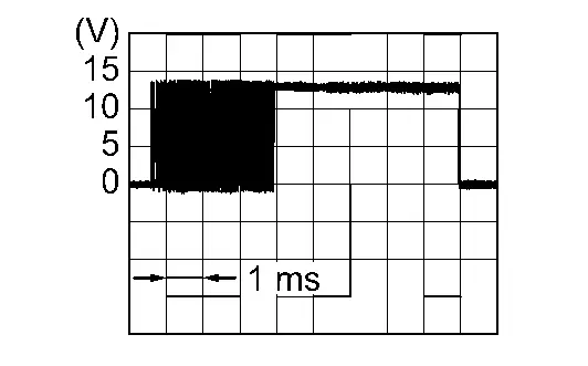
Is the inspection result normal?
YES>>Replace heat pump control unit. Refer to Removal & Installation.
NO>>GO TO 2.
CHECK ELECTRIC EXPANSION VALVE (COOLER) DRIVE SIGNAL CIRCUIT FOR OPEN
-
Power switch OFF.
-
Disconnect heat pump control unit connector and electric expansion valve (cooler) connector.
-
Check continuity between electric expansion valve (cooler) harness connector and heat pump control unit harness connector.
Electric expansion valve (cooler) Heat pump control unit Continuity Connector Terminal Connector Terminal B625 4 M913 29 Existed 1 30 5 31 2 32
Is the inspection result normal?
YES>>GO TO 3.
NO>>Repair harness or connector.
CHECK ELECTRIC EXPANSION VALVE (COOLER) CONTROL CIRCUIT FOR SHORT
-
Check continuity between electric expansion valve (cooler) harness connector and ground.
Electric expansion valve (cooler) — Continuity Connector Terminal B625 4 Ground Not existed 1 5 2 -
Check voltage between electric expansion valve (cooler) harness connector and ground.
+ - Voltage
(Approx.)Electric expansion valve (cooler) Connector Terminal B625 4 Ground 0 V 1 5 2
Is the inspection result normal?
YES>>GO TO 4.
NO>>Repair harness or connector.
CHECK ELECTRIC EXPANSION VALVE (COOLER)
Check electric expansion valve (cooler). Refer to Component Inspection.
Is the inspection result normal?
YES>>Replace heat pump control unit. Refer to Removal & Installation.
NO>>Replace electric expansion valve (cooler). Refer to Removal & Installation.
Component Inspection
CHECK ELECTRIC EXPANSION VALVE (COOLER)
-
Power switch OFF.
-
Disconnect electric expansion valve (cooler) connector.
-
Check resistance between electric expansion valve (cooler) terminals. Refer to applicable table for the normal value.
Terminal Resistance (Ω)
(Approx.)1 4 9
[Temperature condition: 20°C (68°F)]2 5
Is the inspection result normal?
YES>>INSPECTION END
NO>>Replace electric expansion valve (cooler). Refer to Removal & Installation.
P1c05-71 Electric Expansion Valve (heater) Nissan Ariya
DTC Description
DTC DETECTION LOGIC
| DTC No. | CONSULT screen terms | DTC detection condition | |
|---|---|---|---|
| P1C05-71 | Electric expansion valve (heater) | Diagnosis condition | Power switch ON |
| Signal (Terminal) | Electric expansion valve (heater) drive signal circuit | ||
| Threshold | When the drive signal error of electric expansion valve (heater) is detected | ||
| Diagnosis delay time | 4 seconds or more | ||
POSSIBLE CAUSE
-
Electric expansion valve (heater)
-
Heat pump control unit
-
Harness or connectors [electric expansion valve (heater) circuit is open or shorted]
FAIL-SAFE
Electric compressor operation is stopped
DTC CONFIRMATION PROCEDURE
PERFORM DTC CONFIRMATION PROCEDURE
With CONSULT
-
Power switch ON.
-
Select “Self Diagnostic Result” mode of “HEAT PUMP CONTROL” using CONSULT.
Is DTC detected?
YES>>Refer to Diagnosis Procedure.
NO-1>>To check malfunction symptom before repair: Refer to Intermittent Incident.
NO-2>>Confirmation after repair: INSPECTION END
Diagnosis Procedure
CHECK ELECTRIC EXPANSION VALVE (HEATER) DRIVE SIGNAL
-
Power switch ON.
-
Confirm output waveform between heat pump control unit harness connector with oscilloscope.
| + | - | Condition | Output waveform | |
|---|---|---|---|---|
| Heat pump control unit | ||||
| Connector | Terminal | |||
| M913 | 13 | Ground | When the start “Electric expansion initialize” in “Active Test” mode of “HEAT PUMP CONTROL” |
|
| 14 | ||||
| 15 | ||||
| 16 | ||||
Is the inspection result normal?
YES>>Replace heat pump control unit. Refer to Removal & Installation.
NO>>GO TO 2.
CHECK ELECTRIC EXPANSION VALVE (HEATER) DRIVE SIGNAL CIRCUIT FOR OPEN
-
Power switch OFF.
-
Disconnect heat pump control unit connector and electric expansion valve (heater) connector.
-
Check continuity between electric expansion valve (heater) harness connector and heat pump control unit harness connector.
Electric expansion valve (heater) Heat pump control unit Continuity Connector Terminal Connector Terminal B750 2 M913 13 Existed 5 14 1 15 4 16
Is the inspection result normal?
YES>>GO TO 3.
NO>>Repair harness or connector.
CHECK ELECTRIC EXPANSION VALVE (HEATER) CONTROL CIRCUIT FOR SHORT
-
Check continuity between electric expansion valve (heater) harness connector and ground.
Electric expansion valve (heater) — Continuity Connector Terminal B750 2 Ground Not existed 5 1 4 -
Check voltage between electric expansion valve (heater) harness connector and ground.
+ - Voltage
(Approx.)Electric expansion valve (heater) Connector Terminal B750 2 Ground 0 V 5 1 4
Is the inspection result normal?
YES>>GO TO 4.
NO>>Repair harness or connector.
CHECK ELECTRIC EXPANSION VALVE (HEATER)
Check electric expansion valve (heater). Refer to Component Inspection.
Is the inspection result normal?
YES>>Replace heat pump control unit. Refer to Removal & Installation.
NO>>Replace electric expansion valve (heater). Refer to Removal & Installation.
Component Inspection
CHECK ELECTRIC EXPANSION VALVE (HEATER)
-
Power switch OFF.
-
Disconnect electric expansion valve (heater) connector.
-
Check resistance between electric expansion valve (heater) terminals. Refer to applicable table for the normal value.
Terminal Resistance (Ω)
(Approx.)1 4 9
[Temperature condition: 20°C (68°F)]2 5
Is the inspection result normal?
YES>>INSPECTION END
NO>>Replace electric expansion valve (heater). Refer to Removal & Installation.
P1c06-1f Electric Compressor Nissan Ariya 2023
DTC Description
DTC DETECTION LOGIC
| DTC No. | CONSULT screen terms | DTC detection condition | |
|---|---|---|---|
| P1C06–1F | Electric compressor HVIL circuit | Diagnosis condition | Nissan Ariya Vehicle is READY |
| Signal (terminal) | — | ||
| Threshold | When HVIL open circuit is detected in electric compressor | ||
| Diagnosis delay time | Less than 1 second | ||
POSSIBLE CAUSE
-
High voltage harness connector connecting malfunction
-
High voltage harness connector
-
Electric compressor
FAIL-SAFE
Electric compressor operation is stopped
DTC CONFIRMATION PROCEDURE
PERFORM DTC CONFIRMATION PROCEDURE
With CONSULT
-
Power switch OFF.
-
Set the Nissan Ariya vehicle to READY.
-
Operate the air conditioning system.
-
Set the temperature to full cold.
-
Select “Self Diagnostic Result” mode of “HEAT PUMP CONTROL” using CONSULT.
Is DTC detected?
YES>>Refer to Diagnosis Procedure.
NO-1>>To check malfunction symptom before repair: Refer to Intermittent Incident.
NO-2>>Confirmation after repair: INSPECTION END
Diagnosis Procedure
WARNING:
Since hybrid vehicles and electric Nissan Ariya vehicles contain a high voltage battery, there is the risk of electric shock, electric leakage, or similar accidents if the high voltage component and Nissan Ariya vehicle are handled incorrectly. Be sure to follow the correct work procedures when performing inspection and maintenance.
WARNING:
-
Be sure to remove the service plug in order to disconnect the high voltage circuits before performing inspection or maintenance of high voltage system harnesses and parts.
-
The removed service plug must always be carried in a pocket of the responsible worker or placed in the tool box during the procedure to prevent the plug from being connected by mistake.
-
Be sure to wear insulating protective equipment consisting of glove, shoes, face shield and glasses before beginning work on the high voltage system.
-
Never allow workers other than the responsible person to touch the Nissan Ariya vehicle containing high voltage parts. To keep others from touching the high voltage parts, these parts must be covered with an insulating sheet except when using them.
-
Refer to Precautions for High Voltage.
CAUTION:
Never bring the vehicle into the READY status with the service plug removed unless otherwise instructed in the Service Manual. A malfunction may occur if this is not observed.
DIAGNOSIS PROCEDURE
CAUTION:
Erase DTC after the work is completed.
PRECONDITIONING
WARNING:
Follow the instructions below before starting the procedure.
-
Disconnect high voltage circuit. Refer to HOW TO DISCONNECT HIGH VOLTAGE : Precautions.
-
Check voltage in high voltage circuit. Refer to CHECK VOLTAGE IN HIGH VOLTAGE CIRCUIT : Precautions.
>>
GO TO 2.
CHECK THE CONNECTION STATUS OF THE ELECTRIC COMPRESSOR HIGH VOLTAGE HARNESS CONNECTOR
Check that the high voltage harness connector of electric compressor is connected normally.
Is the inspection result normal?
YES>>GO TO 3.
NO>>Reconnect the high voltage harness connector. If reconnecting is impossible due to high voltage harness connector malfunction, replace the high voltage harness between electric compressor and high voltage junction box.
CHECK THE ELECTRIC COMPRESSOR HIGH VOLTAGE HARNESS CONNECTOR
-
Disconnect the electric compressor high voltage harness connector.
-
Check for any adhering foreign substances, cracking, or damage on the high voltage harness connector terminal of electric compressor.
Is the inspection result normal?
YES>>GO TO 4.
NO>>Replace the high voltage harness between electric compressor and high voltage junction box.
CHECK THE HVIL CIRCUIT OF THE ELECTRIC COMPRESSOR HIGH VOLTAGE HARNESS CONNECTOR
Check for continuity between HVIL circuit terminals of electric compressor Nissan Ariya vehicle side high voltage harness connector. Refer to Component Inspection.
Is the inspection result normal?
YES>>Replace electric compressor. Refer to Removal & Installation.
NO>>Replace the high voltage harness between electric compressor and high voltage junction box.
P1c07-49 Heat Pump Control Unit Nissan Ariya 1st generation
DTC Description
DTC DETECTION LOGIC
| DTC No. | CONSULT screen terms | DTC detection condition | |
|---|---|---|---|
| P1C07–49 | Heat pump control unit LIN communication error | Diagnosis condition | Power switch ON |
| Signal (terminal) | — | ||
| Threshold | When an abnormality is detected in the IC for LIN communication | ||
| Diagnosis delay time | 2 seconds or more | ||
POSSIBLE CAUSE
Heat pump control unit
FAIL-SAFE
Electric compressor operation is stopped
DTC CONFIRMATION PROCEDURE
PERFORM DTC CONFIRMATION PROCEDURE
With CONSULT
-
Power switch ON.
-
Select “Self Diagnostic Result” mode of “HEAT PUMP CONTROL” using CONSULT.
Is DTC detected?
YES>>Refer to Diagnosis Procedure.
NO-1>>To check malfunction symptom before repair: Refer to Intermittent Incident.
NO-2>>Confirmation after repair: INSPECTION END
Diagnosis Procedure
REPLACE HEAT PUMP CONTROL UNIT
Replace heat pump control unit. Refer to Removal & Installation.
>>
INSPECTION END
P1c0e-A2 Heat Pump Control Unit Power Supply Nissan Ariya 1st generation
DTC Description
DTC DETECTION LOGIC
| DTC No. | CONSULT screen terms | DTC detection condition | |
|---|---|---|---|
| P1C0E-A2 | Heat pump control unit low voltage power supply | Diagnosis condition | Power switch ON |
| Signal (Terminal) | Heat pump control unit power supply | ||
| Threshold | Power supply voltage supplied to heat pump C/U is too low (less than 10.5 V) | ||
| Diagnosis delay time | — | ||
POSSIBLE CAUSE
-
Heat pump control unit
-
Harness or connector (heat pump control unit power supply circuits is open or shorted)
FAIL-SAFE
Electric compressor operation is stopped
DTC CONFIRMATION PROCEDURE
PERFORM DTC CONFIRMATION PROCEDURE
With CONSULT
-
Power switch ON.
-
Select “Self Diagnostic Result” mode of “HEAT PUMP CONTROL” using CONSULT.
Is DTC detected?
YES>>Refer to Diagnosis Procedure.
NO-1>>To check malfunction symptom before repair: Refer to Intermittent Incident.
NO-2>>Confirmation after repair: INSPECTION END
Diagnosis Procedure
CHECK HEAT PUMP CONTROL UNIT POWER SUPPLY AND GROUND CIRCUITS
Check heat pump control unit power supply and ground circuits. Refer to Diagnosis Procedure.
Is the inspection result normal?
YES>>Replace heat pump control unit. Refer to Removal & Installation.
NO>>Repair or replace malfunctioning parts.
P1c10-11 Refrigerant Temperature Sensor (battery Chiller Inlet) Nissan Ariya: FE0
DTC Description
DTC DETECTION LOGIC
| DTC No. | CONSULT screen terms | DTC detection condition | |
|---|---|---|---|
| P1C10-11 | Refrigerant temperature sensor (battery chiller inlet) | Diagnosis condition | Power switch ON |
| Signal (Terminal) | Refrigerant temperature sensor (battery chiller inlet) signal | ||
| Threshold | The refrigerant temperature sensor (battery chiller inlet) recognition temperature is too high [more than 162°C (323°F)] | ||
| Diagnosis delay time | 4 seconds or more | ||
POSSIBLE CAUSE
-
Refrigerant temperature sensor (battery chiller inlet)
-
Heat pomp control unit
-
Harness or connectors (the sensor circuit is shorted to ground)
FAIL-SAFE
Operate only cooler
DTC CONFIRMATION PROCEDURE
PERFORM DTC CONFIRMATION PROCEDURE
With CONSULT
-
Power switch ON.
-
Select “Self Diagnostic Result” mode of “HEAT PUMP CONTROL” using CONSULT.
Is DTC detected?
YES>>Refer to Diagnosis Procedure.
NO-1>>To check malfunction symptom before repair: Refer to Intermittent Incident.
NO-2>>Confirmation after repair: INSPECTION END
Diagnosis Procedure
CHECK REFRIGERANT TEMPERATURE SENSOR (BATTERY CHILLER INLET) SIGNAL
-
Power switch ON.
-
Check voltage between heat pump control unit harness connector.
+ - Voltage Heat pump control unit Connector Terminal Connector Terminal M914 33 M913 27
Is the inspection result normal?
YES>>Replace heat pump control unit. Refer to Removal & Installation.
NO>>GO TO 2.
CHECK REFRIGERANT TEMPERATURE SENSOR (BATTERY CHILLER INLET) POWER SUPPLY
-
Power switch OFF.
-
Disconnect refrigerant temperature sensor (battery chiller inlet) connector.
-
Power switch ON.
-
Check voltage between refrigerant temperature sensor (battery chiller inlet) harness connector and ground.
+ - Voltage
(Approx.)Refrigerant temperature sensor (battery chiller inlet) Connector Terminal B46 1 Ground 5 V
Is the inspection result normal?
YES>>GO TO 3.
NO>>GO TO 4.
CHECK REFRIGERANT TEMPERATURE SENSOR (BATTERY CHILLER INLET)
Check refrigerant temperature sensor (battery chiller inlet). Refer to Component Inspection.
Is the inspection result normal?
YES>>Replace heat pump control unit. Refer to Removal & Installation.
NO>>Replace refrigerant temperature sensor (battery chiller inlet). Refer to Removal & Installation.
CHECK REFRIGERANT TEMPERATURE SENSOR (BATTERY CHILLER INLET) POWER SUPPLY CIRCUIT FOR SHORT
-
Power switch OFF.
-
Disconnect heat pump control unit connector.
-
Check continuity between refrigerant temperature sensor (battery chiller inlet) harness connector and ground.
Refrigerant temperature sensor (battery chiller inlet) — Continuity Connector Terminal B46 1 Ground Not existed
Is the inspection result normal?
YES>>Replace heat pump control unit. Refer to Removal & Installation.
NO>>Repair harness or connector.
Component Inspection
CHECK REFRIGERANT TEMPERATURE SENSOR (BATTERY CHILLER INLET)
-
Power switch OFF.
-
Remove refrigerant temperature sensor (battery chiller inlet). Refer to Removal & Installation.
-
Check resistance between refrigerant temperature sensor (battery chiller inlet) harness connector terminals. Refer to applicable table for the normal value.
Terminal Condition Resistance: kΩ Temperature: °C (°F) 1 2 −20 (−4) 15.86 −10 (14) 9.58 0 (32) 6.00 10 (50) 3.89 20 (68) 2.59 25 (77) 2.14 30 (86) 1.78 40 (104) 1.25
Is the inspection result normal?
YES>>INSPECTION END
NO>>Replace refrigerant temperature sensor (battery chiller inlet). Refer to Removal & Installation.
P1c10-12 Refrigerant Temperature Sensor (battery Chiller Inlet) Nissan Ariya SUV
DTC Description
DTC DETECTION LOGIC
| DTC No. | CONSULT screen terms | DTC detection condition | |
|---|---|---|---|
| P1C10–12 | Refrigerant temperature sensor (battery chiller inlet) | Diagnosis condition | Power switch ON |
| Signal (Terminal) | Refrigerant temperature sensor (battery chiller inlet) signal | ||
| Threshold | The refrigerant temperature sensor (battery chiller inlet) recognition temperature is too low [less than -60°C (-76°F)] | ||
| Diagnosis delay time | 4 seconds or more | ||
POSSIBLE CAUSE
-
Refrigerant temperature sensor (battery chiller inlet)
-
Heat pomp control unit
-
Harness or connectors (the sensor circuit is open or shorted)
FAIL-SAFE
Operate only cooler
DTC CONFIRMATION PROCEDURE
PERFORM DTC CONFIRMATION PROCEDURE
With CONSULT
-
Power switch ON.
-
Select “Self Diagnostic Result” mode of “HEAT PUMP CONTROL” using CONSULT.
Is DTC detected?
YES>>Refer to Diagnosis Procedure.
NO-1>>To check malfunction symptom before repair: Refer to Intermittent Incident.
NO-2>>Confirmation after repair: INSPECTION END
Diagnosis Procedure
CHECK REFRIGERANT TEMPERATURE SENSOR (BATTERY CHILLER INLET) SIGNAL
-
Power switch ON.
-
Check voltage between heat pump control unit harness connector.
+ - Voltage Heat pump control unit Connector Terminal Connector Terminal M914 33 M913 27
Is the inspection result normal?
YES>>Replace heat pump control unit. Refer to Removal & Installation.
NO>>GO TO 2.
CHECK REFRIGERANT TEMPERATURE SENSOR (BATTERY CHILLER INLET) POWER SUPPLY
-
Power switch OFF.
-
Disconnect refrigerant temperature sensor (battery chiller inlet) connector.
-
Power switch ON.
-
Check voltage between refrigerant temperature sensor (battery chiller inlet) harness connector and ground.
+ - Voltage
(Approx.)Refrigerant temperature sensor (battery chiller inlet) Connector Terminal B46 1 Ground 5 V
Is the inspection result normal?
YES>>GO TO 3.
NO>>GO TO 4.
CHECK REFRIGERANT TEMPERATURE SENSOR (BATTERY CHILLER INLET)
Check refrigerant temperature sensor (battery chiller inlet). Refer to Component Inspection.
Is the inspection result normal?
YES>>Replace heat pump control unit. Refer to Removal & Installation.
NO>>Replace refrigerant temperature sensor (battery chiller inlet). Refer to Removal & Installation.
CHECK REFRIGERANT TEMPERATURE SENSOR (BATTERY CHILLER INLET) POWER SUPPLY CIRCUIT FOR SHORT
-
Power switch OFF.
-
Disconnect heat pump control unit connector.
-
Check continuity between refrigerant temperature sensor (battery chiller inlet) harness connector and ground.
Refrigerant temperature sensor (battery chiller inlet) — Continuity Connector Terminal B46 1 Ground Not existed
Is the inspection result normal?
YES>>Replace heat pump control unit. Refer to Removal & Installation.
NO>>Repair harness or connector.
Component Inspection
CHECK REFRIGERANT TEMPERATURE SENSOR (BATTERY CHILLER INLET)
-
Power switch OFF.
-
Remove refrigerant temperature sensor (battery chiller inlet). Refer to Removal & Installation.
-
Check resistance between refrigerant temperature sensor (battery chiller inlet) harness connector terminals. Refer to applicable table for the normal value.
Terminal Condition Resistance: kΩ Temperature: °C (°F) 1 2 −20 (−4) 15.86 −10 (14) 9.58 0 (32) 6.00 10 (50) 3.89 20 (68) 2.59 25 (77) 2.14 30 (86) 1.78 40 (104) 1.25
Is the inspection result normal?
YES>>INSPECTION END
NO>>Replace refrigerant temperature sensor (battery chiller inlet). Refer to Removal & Installation.
P1c11-11 Refrigerant Temperature Sensor (battery Chiller Outlet) Nissan Ariya 1st generation
DTC Description
DTC DETECTION LOGIC
| DTC No. | CONSULT screen terms | DTC detection condition | |
|---|---|---|---|
| P1C11-11 | Refrigerant temperature sensor (battery chiller outlet) | Diagnosis condition | Power switch ON |
| Signal (Terminal) | Refrigerant temperature sensor (battery chiller outlet) signal | ||
| Threshold | The refrigerant temperature sensor (battery chiller outlet) recognition temperature is too high [more than 162°C (323°F)] | ||
| Diagnosis delay time | 4 seconds or more | ||
POSSIBLE CAUSE
-
Refrigerant temperature sensor (battery chiller outlet)
-
Heat pomp control unit
-
Harness or connectors (the sensor circuit is shorted to ground)
FAIL-SAFE
Operate only cooler
DTC CONFIRMATION PROCEDURE
PERFORM DTC CONFIRMATION PROCEDURE
With CONSULT
-
Power switch ON.
-
Select “Self Diagnostic Result” mode of “HEAT PUMP CONTROL” using CONSULT.
Is DTC detected?
YES>>Refer to Diagnosis Procedure.
NO-1>>To check malfunction symptom before repair: Refer to Intermittent Incident.
NO-2>>Confirmation after repair: INSPECTION END
Diagnosis Procedure
CHECK REFRIGERANT TEMPERATURE SENSOR (BATTERY CHILLER OUTLET) SIGNAL
-
Power switch ON.
-
Check voltage between heat pump control unit harness connector.
+ - Voltage Heat pump control unit Connector Terminal Connector Terminal M914 39 M913 27
Is the inspection result normal?
YES>>Replace heat pump control unit. Refer to Removal & Installation.
NO>>GO TO 2.
CHECK REFRIGERANT TEMPERATURE SENSOR (BATTERY CHILLER OUTLET) POWER SUPPLY
-
Power switch OFF.
-
Disconnect refrigerant temperature sensor (battery chiller outlet) connector.
-
Power switch ON.
-
Check voltage between refrigerant temperature sensor (battery chiller outlet) harness connector and ground.
+ - Voltage
(Approx.)Refrigerant temperature sensor (battery chiller outlet) Connector Terminal B48 1 Ground 5 V
Is the inspection result normal?
YES>>GO TO 3.
NO>>GO TO 4.
CHECK REFRIGERANT TEMPERATURE SENSOR (BATTERY CHILLER OUTLET)
Check refrigerant temperature sensor (battery chiller outlet). Refer to Component Inspection.
Is the inspection result normal?
YES>>Replace heat pump control unit. Refer to Removal & Installation.
NO>>Replace refrigerant temperature sensor (battery chiller outlet). Refer to Removal & Installation.
CHECK REFRIGERANT TEMPERATURE SENSOR (BATTERY CHILLER OUTLET) POWER SUPPLY CIRCUIT FOR SHORT
-
Power switch OFF.
-
Disconnect heat pump control unit connector.
-
Check continuity between refrigerant temperature sensor (battery chiller outlet) harness connector and ground.
Refrigerant temperature sensor (battery chiller outlet) — Continuity Connector Terminal B48 1 Ground Not existed
Is the inspection result normal?
YES>>Replace heat pump control unit. Refer to Removal & Installation.
NO>>Repair harness or connector.
Component Inspection
CHECK REFRIGERANT TEMPERATURE SENSOR (BATTERY CHILLER OUTLET)
-
Power switch OFF.
-
Remove refrigerant temperature sensor (battery chiller outlet). Refer to Removal & Installation.
-
Check resistance between refrigerant temperature sensor (battery chiller outlet) harness connector terminals. Refer to applicable table for the normal value.
Terminal Condition Resistance: kΩ Temperature: °C (°F) 1 2 −20 (−4) 15.86 −10 (14) 9.58 0 (32) 6.00 10 (50) 3.89 20 (68) 2.59 25 (77) 2.14 30 (86) 1.78 40 (104) 1.25
Is the inspection result normal?
YES>>INSPECTION END
NO>>Replace refrigerant temperature sensor (battery chiller outlet). Refer to Removal & Installation.
P1c11-12 Refrigerant Temperature Sensor (battery Chiller Outlet) Nissan Ariya
DTC Description
DTC DETECTION LOGIC
| DTC No. | CONSULT screen terms | DTC detection condition | |
|---|---|---|---|
| P1C11-12 | Refrigerant temperature sensor (battery chiller outlet) | Diagnosis condition | Power switch ON |
| Signal (Terminal) | Refrigerant temperature sensor (battery chiller outlet) signal | ||
| Threshold | The refrigerant temperature sensor (battery chiller outlet) recognition temperature is too low [less than -60°C (-76°F)] | ||
| Diagnosis delay time | 4 seconds or more | ||
POSSIBLE CAUSE
-
Refrigerant temperature sensor (battery chiller outlet)
-
Heat pomp control unit
-
Harness or connectors (the sensor circuit is open or shorted)
FAIL-SAFE
Operate only cooler
DTC CONFIRMATION PROCEDURE
PERFORM DTC CONFIRMATION PROCEDURE
With CONSULT
-
Power switch ON.
-
Select “Self Diagnostic Result” mode of “HEAT PUMP CONTROL” using CONSULT.
Is DTC detected?
YES>>Refer to Diagnosis Procedure.
NO-1>>To check malfunction symptom before repair: Refer to Intermittent Incident.
NO-2>>Confirmation after repair: INSPECTION END
Diagnosis Procedure
CHECK REFRIGERANT TEMPERATURE SENSOR (BATTERY CHILLER OUTLET) SIGNAL
-
Power switch ON.
-
Check voltage between heat pump control unit harness connector.
+ - Voltage Heat pump control unit Connector Terminal Connector Terminal M914 39 M913 27
Is the inspection result normal?
YES>>Replace heat pump control unit. Refer to Removal & Installation.
NO>>GO TO 2.
CHECK REFRIGERANT TEMPERATURE SENSOR (BATTERY CHILLER OUTLET) POWER SUPPLY
-
Power switch OFF.
-
Disconnect refrigerant temperature sensor (battery chiller outlet) connector.
-
Power switch ON.
-
Check voltage between refrigerant temperature sensor (battery chiller outlet) harness connector and ground.
+ - Voltage
(Approx.)Refrigerant temperature sensor (battery chiller outlet) Connector Terminal B48 1 Ground 5 V
Is the inspection result normal?
YES>>GO TO 3.
NO>>GO TO 4.
CHECK REFRIGERANT TEMPERATURE SENSOR (BATTERY CHILLER OUTLET)
Check refrigerant temperature sensor (battery chiller outlet). Refer to Component Inspection.
Is the inspection result normal?
YES>>Replace heat pump control unit. Refer to Removal & Installation.
NO>>Replace refrigerant temperature sensor (battery chiller outlet). Refer to Removal & Installation.
CHECK REFRIGERANT TEMPERATURE SENSOR (BATTERY CHILLER OUTLET) POWER SUPPLY CIRCUIT FOR SHORT
-
Power switch OFF.
-
Disconnect heat pump control unit connector.
-
Check continuity between refrigerant temperature sensor (battery chiller outlet) harness connector and ground.
Refrigerant temperature sensor (battery chiller outlet) — Continuity Connector Terminal B48 1 Ground Not existed
Is the inspection result normal?
YES>>Replace heat pump control unit. Refer to Removal & Installation.
NO>>Repair harness or connector.
Component Inspection
CHECK REFRIGERANT TEMPERATURE SENSOR (BATTERY CHILLER OUTLET)
-
Power switch OFF.
-
Remove refrigerant temperature sensor (battery chiller outlet). Refer to Removal & Installation.
-
Check resistance between refrigerant temperature sensor (battery chiller outlet) harness connector terminals. Refer to applicable table for the normal value.
Terminal Condition Resistance: kΩ Temperature: °C (°F) 1 2 −20 (−4) 15.86 −10 (14) 9.58 0 (32) 6.00 10 (50) 3.89 20 (68) 2.59 25 (77) 2.14 30 (86) 1.78 40 (104) 1.25
Is the inspection result normal?
YES>>INSPECTION END
NO>>Replace refrigerant temperature sensor (battery chiller outlet). Refer to Removal & Installation.
P1c12-93 Expansion Valve (battery Chiller) Nissan Ariya: FE0
DTC Description
DTC DETECTION LOGIC
| DTC No. | CONSULT screen terms | DTC detection condition | |
|---|---|---|---|
| P1C12-93 | Expansion valve (battery chiller) | Diagnosis condition | Power switch ON |
| Signal (Terminal) | Expansion valve (battery chiller) drive signal circuit | ||
| Threshold | When the drive signal error of expansion valve (battery chiller) is detected | ||
| Diagnosis delay time | 4 seconds or more | ||
POSSIBLE CAUSE
-
Expansion valve (battery chiller)
-
Heat pump control unit
-
Harness or connectors [expansion valve (battery chiller) circuit is open or shorted]
FAIL-SAFE
Electric compressor operation is stopped
DTC CONFIRMATION PROCEDURE
PERFORM DTC CONFIRMATION PROCEDURE
With CONSULT
-
Power switch ON.
-
Select “Self Diagnostic Result” mode of “HEAT PUMP CONTROL” using CONSULT.
Is DTC detected?
YES>>Refer to Diagnosis Procedure.
NO-1>>To check malfunction symptom before repair: Refer to Intermittent Incident.
NO-2>>Confirmation after repair: INSPECTION END
Diagnosis Procedure
CHECK EXPANSION VALVE (BATTERY CHILLER) DRIVE SIGNAL
-
Power switch ON.
-
Confirm output waveform between heat pump control unit harness connector with oscilloscope.
| + | - | Condition | Output waveform | |
|---|---|---|---|---|
| Heat pump control unit | ||||
| Connector | Terminal | |||
| M914 | 37 | Ground | When the start “Electric expansion initialize” in “Active Test” mode of “HEAT PUMP CONTROL” |
|
| 38 | ||||
| 43 | ||||
| 44 | ||||
Is the inspection result normal?
YES>>Replace heat pump control unit. Refer to Removal & Installation.
NO>>GO TO 2.
CHECK EXPANSION VALVE (BATTERY CHILLER) DRIVE SIGNAL CIRCUIT FOR OPEN
-
Power switch OFF.
-
Disconnect heat pump control unit connector and expansion valve (battery chiller) connector.
-
Check continuity between expansion valve (battery chiller) harness connector and heat pump control unit harness connector.
Expansion valve (battery chiller) Heat pump control unit Continuity Connector Terminal Connector Terminal B626 2 M914 37 Existed 5 38 4 43 1 44
Is the inspection result normal?
YES>>GO TO 3.
NO>>Repair harness or connector.
CHECK EXPANSION VALVE (BATTERY CHILLER) CONTROL CIRCUIT FOR SHORT
-
Check continuity between expansion valve (battery chiller) harness connector and ground.
Expansion valve (battery chiller) — Continuity Connector Terminal B626 2 Ground Not existed 5 4 1 -
Check voltage between expansion valve (battery chiller) harness connector and ground.
+ - Voltage
(Approx.)Expansion valve (battery chiller) Connector Terminal B626 2 Ground 0 V 5 4 1
Is the inspection result normal?
YES>>GO TO 4.
NO>>Repair harness or connector.
CHECK EXPANSION VALVE (BATTERY CHILLER)
Check expansion valve (battery chiller). Refer to Component Inspection.
Is the inspection result normal?
YES>>Replace heat pump control unit. Refer to Removal & Installation.
NO>>Replace expansion valve (battery chiller). Refer to Removal & Installation.
Component Inspection
CHECK EXPANSION VALVE (BATTERY CHILLER)
-
Power switch OFF.
-
Disconnect expansion valve (battery chiller) connector.
-
Check resistance between expansion valve (battery chiller) terminals. Refer to applicable table for the normal value.
Terminal Resistance (Ω)
(Approx.)1 4 9
[Temperature condition: 20°C (68°F)]2 5
Is the inspection result normal?
YES>>INSPECTION END
NO>>Replace expansion valve (battery chiller). Refer to Removal & Installation.
U1d20-87 Electric Compressor Nissan Ariya SUV
DTC Description
DTC DETECTION LOGIC
| DTC No. | CONSULT screen terms | DTC detection condition | |
|---|---|---|---|
| U1D20–87 | Electric compressor LIN communication error | Diagnosis condition | Power switch ON |
| Signal (terminal) | LIN (electric compressor) signal | ||
| Threshold | Detects abnormalities in the signal transmitted from the electric compressor | ||
| Diagnosis delay time | 2 seconds or more | ||
POSSIBLE CAUSE
-
Electric compressor
-
Heat pump control unit
-
Harness or connectors (electric compressor circuit is open or shorted)
FAIL-SAFE
Electric compressor operation is stopped
DTC CONFIRMATION PROCEDURE
PERFORM DTC CONFIRMATION PROCEDURE
With CONSULT
-
Power switch OFF.
-
Select “Self Diagnostic Result” mode of “HEAT PUMP CONTROL” using CONSULT.
Is DTC detected?
YES>>Refer to Diagnosis Procedure.
NO-1>>To check malfunction symptom before repair: Refer to Intermittent Incident.
NO-2>>Confirmation after repair: INSPECTION END
Diagnosis Procedure
CHECK ELECTRIC COMPRESSOR LIN SIGNAL CIRCUIT FOR OPEN
-
Power switch OFF.
-
Disconnect electric compressor and heat pump control unit connector.
-
Check continuity between electric compressor harness connector and heat pump control unit harness connector.
Electric compressor Heat pump control unit Continuity Connector Terminal Connector Terminal F7 2 M913 4 Existed
Is the inspection result normal?
YES>>GO TO 2.
NO>>Repair harness or connector.
CHECK ELECTRIC COMPRESSOR LIN SIGNAL CIRCUIT FOR SHORT
-
Disconnect following connectors.
-
PTC heater
-
A/C auto amp.
-
Li-ion battery
-
-
Check continuity between electric compressor harness connector and ground.
Electric compressor — Continuity Connector Terminal F7 2 Ground Not existed
Is the inspection result normal?
YES>>GO TO 3.
NO>>Repair harness or connector.
CHECK ELECTRIC COMPRESSOR POWER SUPPLY
-
Power switch ON.
-
Check voltage between electric compressor harness connector and ground.
+ − Voltage Electric compressor Connector Terminal F7 4 Ground Battery voltage
Is the inspection result normal?
YES>>GO TO 4.
NO>>Repair or replace electric compressor 12 V power supply circuit.
CHECK ELECTRIC COMPRESSOR GROUND CIRCUIT FOR OPEN
-
Power switch OFF.
-
Check continuity between electric compressor harness connector and ground.
| Electric compressor | — | Continuity | |
|---|---|---|---|
| Connector | Terminal | ||
| F7 | 5 | Ground | Existed |
Is the inspection result normal?
YES>>GO TO 5.
NO>>Repair harness or connector.
CHECK HEAT PUMP CONTROL UNIT
-
Reconnect all harness connectors disconnected.
-
Set the Nissan Ariya vehicle to READY.
-
Check that the electric compressor operates normally in each mode.
Is the inspection result normal?
YES>>GO TO 6.
NO>>Replace heat pump control unit. (refer to Removal & Installation) GO TO 6.
PERFORM DTC CONFIRMATION PROCEDURE
Perform DTC confirmation procedure. Refer to DTC Description.
Is DTC detected?
YES>>Replace electric compressor. Refer to Removal & Installation.
NO>>INSPECTION END
U1d25-87 A/c Auto Amp. Nissan Ariya first Gen
DTC Description
DTC DETECTION LOGIC
| DTC No. | CONSULT screen terms | DTC detection condition | |
|---|---|---|---|
| U1D25–87 | A/C auto amp. LIN communication error | Diagnosis condition | Power switch ON |
| Signal (terminal) | LIN (A/C auto amp.) signal | ||
| Threshold | Detects abnormalities in the signal transmitted from the A/C auto amp. | ||
| Diagnosis delay time | 2 seconds or more | ||
POSSIBLE CAUSE
-
Heat pump control unit
-
A/C auto amp.
-
Harness or connectors (A/C auto amp. communication circuit is open or shorted)
FAIL-SAFE
Electric compressor operation is stopped
DTC CONFIRMATION PROCEDURE
PERFORM DTC CONFIRMATION PROCEDURE
With CONSULT
-
Power switch ON.
-
Select “Self Diagnostic Result” mode of “HEAT PUMP CONTROL” using CONSULT.
Is DTC detected?
YES>>Refer to Diagnosis Procedure.
NO-1>>To check malfunction symptom before repair: Refer to Intermittent Incident.
NO-2>>Confirmation after repair: INSPECTION END
Diagnosis Procedure
CHECK A/C AUTO AMP. LIN SIGNAL CIRCUIT FOR OPEN
-
Power switch OFF.
-
Disconnect heat pump control unit and A/C auto amp. connector.
-
Check continuity between heat pump control unit harness connector and A/C auto amp. harness connector.
Heat pump control unit A/C auto amp. Continuity Connector Terminal Connector Terminal M913 4 M1 52 Existed
Is the inspection result normal?
YES>>GO TO 2.
NO>>Repair harness or connector.
CHECK A/C AUTO AMP. LIN SIGNAL CIRCUIT FOR SHORT
-
Disconnect following connectors.
-
PTC heater
-
Electric compressor
-
Li-ion battery
-
-
Check continuity between A/C auto amp. harness connector and ground.
A/C auto amp. — Continuity Connector Terminal M1 52 Ground Not existed
Is the inspection result normal?
YES>>GO TO 3.
NO>>Repair harness or connector.
CHECK A/C AUTO AMP. POWER SUPPLY
-
Power switch ON.
-
Check voltage between A/C auto amp. harness connector and ground.
+ − Voltage A/C auto amp. Connector Terminal M1 60 Ground Battery voltage
Is the inspection result normal?
YES>>GO TO 4.
NO>>Repair or replace electric compressor 12 V power supply circuit.
CHECK A/C AUTO AMP. GROUND CIRCUIT FOR OPEN
-
Power switch OFF.
-
Check continuity between A/C auto amp. harness connector and ground.
| A/C auto amp. | — | Continuity | |
|---|---|---|---|
| Connector | Terminal | ||
| M1 | 58 | Ground | Existed |
Is the inspection result normal?
YES>>GO TO 5.
NO>>Repair harness or connector.
CHECK HEAT PUMP CONTROL UNIT
-
Reconnect all harness connectors disconnected.
-
Set the Nissan Ariya vehicle to READY.
-
Perform DTC confirmation procedure. Refer to DTC Description.
Is DTC detected?
YES>>Replace heat pump control unit. (refer to Removal & Installation) GO TO 6.
NO>>GO TO 6.
PERFORM DTC CONFIRMATION PROCEDURE
Perform DTC confirmation procedure. Refer to DTC Description.
Is DTC detected?
YES>>Replace A/C auto amp. Refer to Removal & Installation.
NO>>INSPECTION END
U2143-87 Can Comm Circuit Nissan Ariya: FE0
DTC Description
DESCRIPTION
CAN (Controller Area Network) is a serial communication line for real time applications. It is an on-Nissan Ariya vehicle multiplex communication line with high data communication speed and excellent error detection ability. Modern Nissan Ariya vehicle is equipped with many electronic control unit, and each control unit shares information and links with other control units during operation (not independent). In CAN communication, control units are connected with 2 communication lines (CAN H-line, CAN L-line) allowing a high rate of information transmission with less wiring. Each control unit transmits/receives data but selectively reads required data only.
CAN Communication Signal Chart. Refer to CAN Communication Signal Chart.
DTC DETECTION LOGIC
| DTC No. | CONSULT screen items | DTC Detection Condition | |
|---|---|---|---|
| U2143–87 | CAN communication error (VCM/HCM) | Diagnosis condition | Power switch ON |
| Signal (terminal) | CAN communication signal | ||
| Threshold | Heat pump control unit is not transmitting or receiving CAN communication signal | ||
| Diagnosis delay time | 2 seconds or more | ||
POSSIBLE CAUSE
CAN communication system
FAIL-SAFE
Electric compressor operation is stopped
DTC CONFIRMATION PROCEDURE
PERFORM DTC CONFIRMATION PROCEDURE
With CONSULT
-
Power switch ON.
-
Perform “Self Diagnostic Result” mode of “HEAT PUMP CONTROL” using CONSULT.
Is DTC detected?
YES>>Refer to Diagnosis Procedure.
NO-1>>To check malfunction symptom before repair: Refer to Intermittent Incident.
NO-2>>Confirmation after repair: INSPECTION END
Diagnosis Procedure
CHECK CAN COMMUNICATION SYSTEM
Check CAN communication system. Refer to Trouble Diagnosis Flow Chart.
>>
INSPECTION END
U2148-87 Can Comm Circuit Nissan Ariya first Gen
DTC Description
DESCRIPTION
CAN (Controller Area Network) is a serial communication system for real time application. It is an on-Nissan Ariya vehicle multiplex communication system with high data communication speed and excellent error detection ability. Many electronic control units are equipped onto Nissan Ariya vehicles, and each control unit shares information and links with other control units during operation (not independent). In CAN communication, control units are connected with two communication lines (CAN-H line, CAN-L line) allowing a high rate of information transmission with less wiring. Each control unit transmits/receives data but selectively reads required data only.
CAN Communication Signal Chart. Refer to CAN Communication Signal Chart.
DTC DETECTION LOGIC
| DTC No. | CONSULT screen terms | DTC detection condition | |
|---|---|---|---|
| U2148-87 | CAN communication error (brake control unit) | Diagnosis condition | Power switch ON |
| Signal (Terminal) | CAN communication signal | ||
| Threshold | Heat pump control unit is not transmitting or receiving CAN communication signal | ||
| Diagnosis delay time | 2 seconds or more | ||
POSSIBLE CAUSE
CAN communication system
FAIL-SAFE
Electric compressor operation is stopped
DTC CONFIRMATION PROCEDURE
PERFORM DTC CONFIRMATION PROCEDURE
With CONSULT
-
Power switch ON.
-
Select “Self Diagnostic Result” mode of “HEAT PUMP CONTROL” with CONSULT.
Is DTC detected?
YES>>Refer to Diagnosis Procedure.
NO-1>>To check malfunction symptom before repair: Refer to Intermittent Incident.
NO-2>>Confirmation after repair: INSPECTION END
Diagnosis Procedure
CHECK CAN COMMUNICATION SYSTEM
Check CAN communication system. Refer to Trouble Diagnosis Flow Chart.
>>
INSPECTION END
U214e-87 Can Comm Circuit Nissan Ariya 1st generation
DTC Description
DESCRIPTION
CAN (Controller Area Network) is a serial communication system for real time application. It is an on-Nissan Ariya vehicle multiplex communication system with high data communication speed and excellent error detection ability. Many electronic control units are equipped onto Nissan Ariya vehicles, and each control unit shares information and links with other control units during operation (not independent). In CAN communication, control units are connected with two communication lines (CAN-H line, CAN-L line) allowing a high rate of information transmission with less wiring. Each control unit transmits/receives data but selectively reads required data only.
CAN Communication Signal Chart. Refer to CAN Communication Signal Chart.
DTC DETECTION LOGIC
| DTC No. | CONSULT screen terms | DTC detection condition | |
|---|---|---|---|
| U214E-87 | CAN communication error (combination meter) | Diagnosis condition | Power switch ON |
| Signal (Terminal) | CAN communication signal | ||
| Threshold | Heat pump control unit is not transmitting or receiving CAN communication signal | ||
| Diagnosis delay time | 2 seconds or more | ||
POSSIBLE CAUSE
CAN communication system
FAIL-SAFE
Electric compressor operation is stopped
DTC CONFIRMATION PROCEDURE
PERFORM DTC CONFIRMATION PROCEDURE
With CONSULT
-
Power switch ON.
-
Select “Self Diagnostic Result” mode of “HEAT PUMP CONTROL” with CONSULT.
Is DTC detected?
YES>>Refer to Diagnosis Procedure.
NO-1>>To check malfunction symptom before repair: Refer to Intermittent Incident.
NO-2>>Confirmation after repair: INSPECTION END
Diagnosis Procedure
CHECK CAN COMMUNICATION SYSTEM
Check CAN communication system. Refer to Trouble Diagnosis Flow Chart.
>>
INSPECTION END
U214f-87 Can Comm Circuit Nissan Ariya SUV
DTC Description
DESCRIPTION
CAN (Controller Area Network) is a serial communication system for real time application. It is an on-Nissan Ariya vehicle multiplex communication system with high data communication speed and excellent error detection ability. Many electronic control units are equipped onto Nissan Ariya vehicles, and each control unit shares information and links with other control units during operation (not independent). In CAN communication, control units are connected with two communication lines (CAN-H line, CAN-L line) allowing a high rate of information transmission with less wiring. Each control unit transmits/receives data but selectively reads required data only.
CAN Communication Signal Chart. Refer to CAN Communication Signal Chart.
DTC DETECTION LOGIC
| DTC No. | CONSULT screen terms | DTC detection condition | |
|---|---|---|---|
| U214F-87 | CAN communication error (BCM) | Diagnosis condition | Power switch ON |
| Signal (Terminal) | CAN communication signal | ||
| Threshold | Heat pump control unit is not transmitting or receiving CAN communication signal | ||
| Diagnosis delay time | 2 seconds or more | ||
POSSIBLE CAUSE
CAN communication system
FAIL-SAFE
Electric compressor operation is stopped
DTC CONFIRMATION PROCEDURE
PERFORM DTC CONFIRMATION PROCEDURE
With CONSULT
-
Power switch ON.
-
Select “Self Diagnostic Result” mode of “HEAT PUMP CONTROL” with CONSULT.
Is DTC detected?
YES>>Refer to Diagnosis Procedure.
NO-1>>To check malfunction symptom before repair: Refer to Intermittent Incident.
NO-2>>Confirmation after repair: INSPECTION END
Diagnosis Procedure
CHECK CAN COMMUNICATION SYSTEM
Check CAN communication system. Refer to Trouble Diagnosis Flow Chart.
>>
INSPECTION END
U2153-87 Can Comm Circuit Nissan Ariya SUV
DTC Description
DESCRIPTION
CAN (Controller Area Network) is a serial communication system for real time application. It is an on-Nissan Ariya vehicle multiplex communication system with high data communication speed and excellent error detection ability. Many electronic control units are equipped onto Nissan Ariya vehicles, and each control unit shares information and links with other control units during operation (not independent). In CAN communication, control units are connected with two communication lines (CAN-H line, CAN-L line) allowing a high rate of information transmission with less wiring. Each control unit transmits/receives data but selectively reads required data only.
CAN Communication Signal Chart. Refer to CAN Communication Signal Chart.
DTC DETECTION LOGIC
| DTC No. | CONSULT screen terms | DTC detection condition | |
|---|---|---|---|
| U2153-87 | CAN communication error (Heating, Ventilating, Air Conditioning) ch1 | Diagnosis condition | Power switch ON |
| Signal (Terminal) | CAN communication signal | ||
| Threshold | Heat pump control unit is not transmitting or receiving CAN communication signal | ||
| Diagnosis delay time | 2 seconds or more | ||
POSSIBLE CAUSE
CAN communication system
FAIL-SAFE
Electric compressor operation is stopped
DTC CONFIRMATION PROCEDURE
PERFORM DTC CONFIRMATION PROCEDURE
With CONSULT
-
Power switch ON.
-
Select “Self Diagnostic Result” mode of “HEAT PUMP CONTROL” with CONSULT.
Is DTC detected?
YES>>Refer to Diagnosis Procedure.
NO-1>>To check malfunction symptom before repair: Refer to Intermittent Incident.
NO-2>>Confirmation after repair: INSPECTION END
Diagnosis Procedure
CHECK CAN COMMUNICATION SYSTEM
Check CAN communication system. Refer to Trouble Diagnosis Flow Chart.
>>
INSPECTION END
U3d01-06 Heat Pump Control Unit Nissan Ariya 2023
DTC Description
DTC DETECTION LOGIC
| DTC No. | CONSULT screen terms | DTC detection condition | |
|---|---|---|---|
| U3D01–06 | Heat pump control unit | Diagnosis condition | Power switch ON |
| Signal (terminal) | — | ||
| Threshold | When an error in the ROM written to the ECU is detected | ||
| Diagnosis delay time | 2 seconds or more | ||
POSSIBLE CAUSE
Heat pump control unit
FAIL-SAFE
Electric compressor operation is stopped
DTC CONFIRMATION PROCEDURE
PERFORM DTC CONFIRMATION PROCEDURE
With CONSULT
-
Power switch ON.
-
Select “Self Diagnostic Result” mode of “HEAT PUMP CONTROL” using CONSULT.
Is DTC detected?
YES>>Refer to Diagnosis Procedure.
NO-1>>To check malfunction symptom before repair: Refer to Intermittent Incident.
NO-2>>Confirmation after repair: INSPECTION END
Diagnosis Procedure
REPLACE HEAT PUMP CONTROL UNIT
Replace heat pump control unit. Refer to Removal & Installation.
>>
INSPECTION END
Power Supply and Ground Circuit (a/c Auto Amp.) Nissan Ariya 2023
Diagnosis Procedure
CHECK A/C AUTO AMP. GROUND CIRCUIT FOR OPEN
-
Power switch OFF.
-
Disconnect A/C auto amp. connector.
-
Check continuity between A/C auto amp. harness connector and ground.
A/C auto amp. — Continuity Connector Terminal M1 58 Ground Existed
Is the inspection result normal?
YES>>GO TO 2.
NO>>Repair harness or connector.
CHECK FUSE
Check that the following fuse is not blown (open).
| Unit | Location | Fuse No. | Capacity |
|---|---|---|---|
| A/C auto amp. | Fuse and fusible link block | #81 | 10A |
NOTE:
For details of fuse, connector and terminal arrangement. Refer to Wiring Diagram.
Is the fuse blown (open)?
YES>>Replace the blown (open) fuse after repairing the affected circuit if a fuse is blown (open).
NO>>GO TO 3.
CHECK A/C AUTO AMP. POWER SUPPLY
-
Connect A/C auto amp. connector.
-
Power switch ON
-
Check voltage between A/C auto amp. harness connector terminals.
A/C auto amp. Voltage Connector Terminal + - M1 60 58 10.5 – 16 V
Is the inspection result normal?
YES>>Replace A/C auto amp. Refer to Removal & Installation.
NO>>Repair the A/C auto amp. power supply circuit.
Power Supply and Ground Circuit (a/c Control) Nissan Ariya 2023
Diagnosis Procedure
CHECK FUSE
-
Power switch OFF.
-
Check that the following fuse is not blown (open).
Unit Location Fuse No. Capacity A/C control Fuse and fusible link block #81 10A NOTE:
For details of fuse, connector and terminal arrangement. Refer to Wiring Diagram.
Is the fuse blown (open)?
YES>>Replace the blown (open) fuse after repairing the affected circuit if a fuse is blown (open).
NO>>GO TO 2.
CHECK A/C CONTROL POWER SUPPLY
-
Disconnect A/C control connector.
-
Power switch ON.
-
Check voltage between A/C control harness connector and ground.
+ - Voltage A/C control Connector Terminal M69 1 Ground Battery voltage
Is the inspection result normal?
YES>>GO TO 3.
NO>>Repair harness or connector between A/C control and fuse.
CHECK A/C CONTROL GROUND CIRCUIT FOR OPEN
-
Power switch OFF.
-
Check continuity between A/C control harness connector and ground.
A/C control — Continuity Connector Terminal M69 6 Ground Existed
Is the inspection result normal?
YES>>Replace A/C control. Refer to Removal & Installation.
NO>>Repair harness or connector.
Power Supply and Ground Circuit (heat Pump Control Unit) Nissan Ariya
Diagnosis Procedure
CHECK HEAT PUMP CONTROL UNIT GROUND CIRCUIT FOR OPEN
-
Power switch OFF.
-
Disconnect heat pump control unit connector.
-
Check continuity between heat pump control unit harness connector and ground.
Heat pump control unit — Continuity Connector Terminal M913 19 Ground Existed 28 M914 40
Is the inspection result normal?
YES>>GO TO 2.
NO>>Repair harness or connector.
CHECK FUSE
Check that the following fuse is not blown (open).
| Unit | Location | Fuse No. | Capacity |
|---|---|---|---|
| Heat pump control unit | Fuse and fusible link block | #81 | 10A |
NOTE:
For details of fuse, connector and terminal arrangement. Refer to Wiring Diagram.
Is the fuse blown (open)?
YES>>Replace the blown (open) fuse after repairing the affected circuit if a fuse is blown (open).
NO>>GO TO 3.
CHECK HEAT PUMP CONTROL UNIT POWER SUPPLY
-
Connect heat pump control unit connector.
-
Power switch ON.
-
Check voltage between heat pump control unit harness connector terminals.
+ - Voltage Heat pump control unit Connector Terminal M913 17 Ground 10.5 – 16 V
Is the inspection result normal?
YES>>Replace heat pump control unit. Refer to Removal & Installation.
NO>>Repair the heat pump control unit power supply circuit.
Blower Motor Circuit Nissan Ariya 2026
Diagnosis Procedure
CHECK FUSIBLE LINK
-
Power switch OFF.
-
Check that the following fusible link is not blown (open).
Unit Location Fusible link No. Capacity Blower relay Fuse and fusible link block #J 50 A NOTE:
For details of fusible link, connector and terminal arrangement. Refer to Wiring Diagram.
Is the fusible link blown (open)?
YES>>Replace the blown (open) fusible link after repairing the affected circuit if a fusible link is blown (open).
NO>>GO TO 2.
CHECK BLOWER MOTOR POWER SUPPLY
-
Disconnect the blower motor connector.
-
Power switch ON.
-
Check voltage between blower motor harness connector and ground.
+ - Voltage Blower motor Connector Terminal M330 2 Ground Battery voltage
Is the inspection result normal?
YES>>GO TO 3.
NO>>GO TO 6.
CHECK BLOWER MOTOR GROUND CIRCUIT FOR OPEN
-
Power switch OFF.
-
Check continuity between blower motor harness connector and ground.
Blower motor — Continuity Connector Terminal M330 4 Ground Existed
Is the inspection result normal?
YES>>GO TO 4.
NO>>Repair the harnesses or connectors.
CHECK BLOWER MOTOR CONTROL SIGNAL
-
Connect blower motor connector.
-
Power switch ON.
-
Check duty ratios between blower motor harness connector and ground by using an oscilloscope.
+ - Condition Output waveform Blower motor Connector Terminal M330 1 Ground Blower motor: OFF 10.5 – 16 V Blower motor: 1st speed (manual) Blower motor: 7th speed (manual)
Is the inspection result normal?
YES>>Replace blower motor. Refer to Removal & Installation.
NO>>GO TO 5.
CHECK BLOWER MOTOR CONTROL SIGNAL CIRCUIT FOR OPEN
-
Power switch OFF.
-
Disconnect blower motor connector and A/C auto amp. connector.
-
Check continuity between blower motor harness connector and A/C auto amp. harness connector.
Blower motor A/C auto amp. Continuity Connector Terminal Connector Terminal M330 1 M2 34 Existed
Is the inspection result normal?
YES>>GO TO 9.
NO>>Repair the harnesses or connectors.
CHECK BLOWER MOTOR POWER SUPPLY CIRCUIT FOR OPEN
-
Power switch OFF.
-
Remove blower relay.
-
Check continuity between blower motor harness connector and blower relay harness connector.
Blower motor Blower relay Continuity Connector Terminal Connector Terminal M330 2 E101 3 Existed
Is the inspection result normal?
YES>>GO TO 7.
NO>>Repair the harnesses or connectors.
CHECK BLOWER MOTOR RELAY GROUND CIRCUIT FOR OPEN (COIL SIDE)
Check continuity between blower relay harness connector and ground.
| Blower relay | — | Continuity | |
|---|---|---|---|
| Connector | Terminal | ||
| E101 | 2 | Ground | Existed |
Is the inspection result normal?
YES>>GO TO 8.
NO>>Repair the harnesses or connectors.
CHECK BLOWER MOTOR RELAY
Check blower relay. Refer to Component Inspection.
Is the inspection result normal?
YES>>Repair the blower relay power supply circuit.
NO>>Replace blower relay.
REPLACE BLOWER MOTOR
-
Replace blower motor. Refer to Removal & Installation.
-
Connect A/C auto amp. connector.
-
Power switch ON.
-
Change fan speed from 1st – 7th, and check that blower motor operates normally.
Is the inspection result normal?
YES>>INSPECTION END
NO>>Replace A/C auto amp. Refer to Removal & Installation.
Component Inspection
CHECK BLOWER RELAY
-
Power switch OFF.
-
Remove blower relay.
-
Check continuity between blower relay terminals.
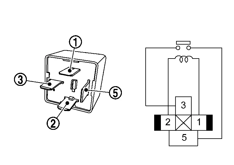
Terminal Condition Continuity Blower relay 12 V direct current supply between terminals and . Existed No current supply Not existed
Is the inspection result normal?
YES>>INSPECTION END
NO>>Replace blower relay.
Blower Motor Nissan Ariya first Gen
Component Inspection
CHECK BLOWER MOTOR-I
-
Remove blower motor. Refer to Removal & Installation.
-
Check that there is not any mixing foreign object in the blower motor.
Is the inspection result normal?
YES>>GO TO 2.
NO>>Remove foreign object in the blower motor.
CHECK BLOWER MOTOR-II
Check that there is not breakage or damage in the blower motor.
Is the inspection result normal?
YES>>GO TO 3.
NO>>Replace blower motor. Refer to Removal & Installation.
CHECK BLOWER MOTOR-III
Check that blower motor turns smoothly.
Is the inspection result normal?
YES>>INSPECTION END
NO>>Replace blower motor. Refer to Removal & Installation.
Door Motor Circuit Nissan Ariya
Diagnosis Procedure
NOTE:
If multiple of door motor DTCs (B2480-93, B24DF-93, B24F5-93, B24F6-93, B24F7-93, B24F8-93)are detected, check this circuit.
CHECK DTC
Check detected DTC of the door motor system.
Detected B2480- 93, B24F5- 93, B24F6- 93>>
GO TO 2.
Detected B24DF- 93, B24F7- 93, B24F8- 93>>GO TO 3.
Detected B2480- 93, B24DF- 93, B24F5- 93, B24F6- 93, B24F7- 93, B24F8- 93>>GO TO 4.
CHECK DOOR MOTOR POWER SUPPLY-1
-
Power switch ON.
-
Check voltage between intake door motor harness connector and ground.
| + | - | Voltage | |
|---|---|---|---|
| Intake door motor | |||
| Connector | Terminal | ||
| M908 | 1 | Ground | 10.5 – 16 V |
Is the inspection result normal?
YES>>INSPECTION END
NO>>GO TO 8.
CHECK DOOR MOTOR POWER SUPPLY-2
-
Power switch ON.
-
Check voltage between air mix door motor RH harness connector and ground.
| + | - | Voltage | |
|---|---|---|---|
| Air mix door motor RH | |||
| Connector | Terminal | ||
| M321 | 1 | Ground | 10.5 – 16 V |
Is the inspection result normal?
YES>>INSPECTION END
NO>>GO TO 9.
CHECK DOOR MOTOR GROUND CIRCUIT FOR OPEN
-
Power switch OFF.
-
Disconnect intake door motor connector and A/C auto amp. connector.
-
Check continuity between intake door motor harness connector and A/C auto amp. harness connector.
Intake door motor A/C auto amp. Continuity Connector Terminal Connector Terminal M908 2 M2 27 Existed
Is the inspection result normal?
YES>>GO TO 5.
NO>>Repair harness or connector.
CHECK DOOR MOTOR LIN SIGNAL
-
Connect intake door motor connector and A/C auto amp. connector.
-
Power switch ON.
-
Confirm output waveform between intake door motor harness connector and A/C auto amp. harness connector with oscilloscope.
+ - Output waveform Intake door motor A/C auto amp. Connector Terminal Connector Terminal M908 3 M1 58
Is the inspection result normal?
YES>>INSPECTION END
NO>>GO TO 6.
CHECK DOOR MOTOR LIN SIGNAL CIRCUIT FOR OPEN
-
Power switch OFF.
-
Disconnect A/C auto amp. and intake door motor connector.
-
Check continuity between intake door motor harness connector and A/C auto amp. harness connector.
Intake door motor A/C auto amp. Continuity Connector Terminal Connector Terminal M908 3 M2 2 Existed
Is the inspection result normal?
YES>>GO TO 7.
NO>>Repair harness or connector.
CHECK DOOR MOTOR LIN SIGNAL CIRCUIT FOR SHORT
-
Disconnect following connectors.
-
Air mix door motor LH
-
Air mix door motor RH
-
Front mode door motor LH
-
Front mode door motor RH
-
Rear mode door motor
-
-
Check continuity between A/C auto amp. harness connector and ground.
A/C auto amp. — Continuity Connector Terminal M2 2 Ground Not existed
Is the inspection result normal?
YES>>Replace A/C auto amp. Refer to Removal & Installation.
NO>>Repair harness or connector.
CHECK DOOR MOTOR POWER SUPPLY CIRCUIT FOR OPEN-1
-
Power switch OFF.
-
Disconnect intake door motor and A/C auto amp. connector.
-
Check continuity between intake door motor harness connector and A/C auto amp. harness connector.
Intake door motor A/C auto amp. Continuity Connector Terminal Connector Terminal M908 1 M2 27 Existed
Is the inspection result normal?
YES>>GO TO 10.
NO>>Repair harness or connector.
CHECK DOOR MOTOR POWER SUPPLY CIRCUIT FOR OPEN-2
-
Power switch OFF.
-
Disconnect air mix door motor RH and A/C auto amp. connector.
-
Check continuity between air mix door motor RH harness connector and A/C auto amp. harness connector.
Air mix door motor RH A/C auto amp. Continuity Connector Terminal Connector Terminal M321 1 M2 1 Existed
Is the inspection result normal?
YES>>GO TO 11.
NO>>Repair harness or connector.
CHECK DOOR MOTOR POWER SUPPLY CIRCUIT FOR SHORT-1
-
Disconnect front mode door motor RH and front mode door motor LH connector.
-
Check continuity between A/C auto amp. harness connector and ground.
A/C auto amp. — Continuity Connector Terminal M2 21 Ground Not existed
Is the inspection result normal?
YES>>Replace A/C auto amp. Refer to Removal & Installation.
NO>>Repair harness or connector.
CHECK DOOR MOTOR POWER SUPPLY CIRCUIT FOR SHORT-2
-
Disconnect air mix door motor LH and rear mode door motor connector.
-
Check continuity between A/C auto amp. harness connector and ground.
A/C auto amp. — Continuity Connector Terminal M2 1 Ground Not existed
Is the inspection result normal?
YES>>Replace A/C auto amp. Refer to Removal & Installation.
NO>>Repair harness or connector.
Electric Compressor Nissan Ariya SUV
Insulation Resistance Check
WARNING:
Since hybrid vehicles and electric Nissan Ariya vehicles contain a high voltage battery, there is the risk of electric shock, electric leakage, or similar accidents if the high voltage component and Nissan Ariya vehicle are handled incorrectly. Be sure to follow the correct work procedures when performing inspection and maintenance.
WARNING:
-
Be sure to remove the service plug in order to disconnect the high voltage circuits before performing inspection or maintenance of high voltage system harnesses and parts.
-
The removed service plug must always be carried in a pocket of the responsible worker or placed in the tool box during the procedure to prevent the plug from being connected by mistake.
-
Be sure to wear insulating protective equipment consisting of glove, shoes, face shield and glasses before beginning work on the high voltage system.
-
Never allow workers other than the responsible person to touch the Nissan Ariya vehicle containing high voltage parts. To keep others from touching the high voltage parts, these parts must be covered with an insulating sheet except when using them.
-
Refer to Precautions for High Voltage.
CAUTION:
Never bring the vehicle into the READY status with the service plug removed unless otherwise instructed in the Service Manual. A malfunction may occur if this is not observed.
DIAGNOSIS PROCEDURE
PRECONDITIONING
WARNING:
Follow the instructions below before starting the procedure.
-
Disconnect high voltage circuit. Refer to HOW TO DISCONNECT HIGH VOLTAGE : Precautions.
-
Check voltage in high voltage circuit. Refer to CHECK VOLTAGE IN HIGH VOLTAGE CIRCUIT : Precautions.
>>
GO TO 2.
CHECK ELECTRIC COMPRESSOR INSULATION RESISTANCE
-
Disconnect high voltage harness connector from electric compressor.
-
Check the insulation resistance of the electric compressor with an insulation resistance tester.
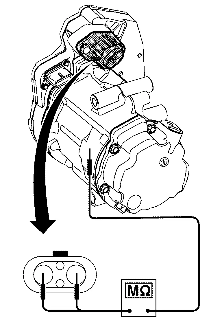
CAUTION:
-
Unlike the ordinary tester, the insulation resistance tester applies 500V when measuring. If used incorrectly, there is the danger of electric shock. If used in the Nissan Ariya vehicle 12V system, there is the danger of damage to electronic devices. Read the insulation resistance tester instruction manual carefully and be sure to work safely.
-
Use 500V range of insulation resistance tester to measure insulation resistance. Wait for 30 seconds until the value becomes stable.
-
| + | − | Resistance |
|---|---|---|
| Electric compressor | ||
| Terminal | ||
| 7 | Aluminum part on side of electric compressor | 3 MΩ or more |
| 8 |
Is the inspection result normal?
YES>>INSPECTION END
NO>>Replace electric compressor. Refer to Removal & Installation.
Component Inspection
WARNING:
Since hybrid vehicles and electric Nissan Ariya vehicles contain a high voltage battery, there is the risk of electric shock, electric leakage, or similar accidents if the high voltage component and Nissan Ariya vehicle are handled incorrectly. Be sure to follow the correct work procedures when performing inspection and maintenance.
WARNING:
-
Be sure to remove the service plug in order to disconnect the high voltage circuits before performing inspection or maintenance of high voltage system harnesses and parts.
-
The removed service plug must always be carried in a pocket of the responsible worker or placed in the tool box during the procedure to prevent the plug from being connected by mistake.
-
Be sure to wear insulating protective equipment consisting of glove, shoes, face shield and glasses before beginning work on the high voltage system.
-
Never allow workers other than the responsible person to touch the Nissan Ariya vehicle containing high voltage parts. To keep others from touching the high voltage parts, these parts must be covered with an insulating sheet except when using them.
-
Refer to Precautions for High Voltage.
CAUTION:
Never bring the vehicle into the READY status with the service plug removed unless otherwise instructed in the Service Manual. A malfunction may occur if this is not observed.
PRECONDITIONING
WARNING:
Follow the instructions below before starting the procedure.
-
Disconnect high voltage circuit. Refer to HOW TO DISCONNECT HIGH VOLTAGE : Precautions.
-
Check voltage in high voltage circuit. Refer to CHECK VOLTAGE IN HIGH VOLTAGE CIRCUIT : Precautions.
>>
GO TO 2.
CHECK ELECTRIC COMPRESSOR
-
Power switch OFF.
-
Disconnect electric compressor connector.
-
Check voltage between electric compressor terminals using circuit tester diode mode.
+ - Voltage Electric compressor Terminal 8 7 0.4 – 1.0 V
Is the inspection result normal?
YES>>INSPECTION END
NO>>Replace electric compressor. Refer to Removal & Installation.
Electric Compressor High Voltage Harness Connector (hvil Circuit) Nissan Ariya
Component Inspection
WARNING:
Since hybrid vehicles and electric Nissan Ariya vehicles contain a high voltage battery, there is the risk of electric shock, electric leakage, or similar accidents if the high voltage component and Nissan Ariya vehicle are handled incorrectly. Be sure to follow the correct work procedures when performing inspection and maintenance.
WARNING:
-
Be sure to remove the service plug in order to disconnect the high voltage circuits before performing inspection or maintenance of high voltage system harnesses and parts.
-
The removed service plug must always be carried in a pocket of the responsible worker or placed in the tool box during the procedure to prevent the plug from being connected by mistake.
-
Be sure to wear insulating protective equipment consisting of glove, shoes, face shield and glasses before beginning work on the high voltage system.
-
Never allow workers other than the responsible person to touch the Nissan Ariya vehicle containing high voltage parts. To keep others from touching the high voltage parts, these parts must be covered with an insulating sheet except when using them.
-
Refer to Precautions for High Voltage.
CAUTION:
Never bring the vehicle into the READY status with the service plug removed unless otherwise instructed in the Service Manual. A malfunction may occur if this is not observed.
PRECONDITIONING
WARNING:
Follow the instructions below before starting the procedure.
-
Disconnect high voltage circuit. Refer to HOW TO DISCONNECT HIGH VOLTAGE : Precautions.
-
Check voltage in high voltage circuit. Refer to CHECK VOLTAGE IN HIGH VOLTAGE CIRCUIT : Precautions.
>>
GO TO 2.
CHECK THE HVIL CIRCUIT OF THE ELECTRIC COMPRESSOR HIGH VOLTAGE HARNESS CONNECTOR
-
Disconnect the cable from the negative terminal of the 12V battery.
-
Disconnect the electric compressor high voltage harness connector.
-
Check for continuity between HVIL circuit terminals of electric compressor Nissan Ariya vehicle side high voltage harness connector using a resistance meter.
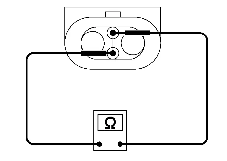
Is the inspection result normal?
YES>>INSPECTION END
NO>>Replace the high voltage harness between electric compressor and high voltage junction box.
Ptc Heater Nissan Ariya 1st generation
Insulation Resistance Check
WARNING:
Since hybrid vehicles and electric Nissan Ariya vehicles contain a high voltage battery, there is the risk of electric shock, electric leakage, or similar accidents if the high voltage component and Nissan Ariya vehicle are handled incorrectly. Be sure to follow the correct work procedures when performing inspection and maintenance.
WARNING:
-
Be sure to remove the service plug in order to disconnect the high voltage circuits before performing inspection or maintenance of high voltage system harnesses and parts.
-
The removed service plug must always be carried in a pocket of the responsible worker or placed in the tool box during the procedure to prevent the plug from being connected by mistake.
-
Be sure to wear insulating protective equipment consisting of glove, shoes, face shield and glasses before beginning work on the high voltage system.
-
Never allow workers other than the responsible person to touch the Nissan Ariya vehicle containing high voltage parts. To keep others from touching the high voltage parts, these parts must be covered with an insulating sheet except when using them.
-
Refer to Precautions for High Voltage.
CAUTION:
Never bring the vehicle into the READY status with the service plug removed unless otherwise instructed in the Service Manual. A malfunction may occur if this is not observed.
DIAGNOSIS PROCEDURE
PRECONDITIONING
WARNING:
Follow the instructions below before starting the procedure.
-
Disconnect high voltage circuit. Refer to HOW TO DISCONNECT HIGH VOLTAGE : Precautions.
-
Check voltage in high voltage circuit. Refer to CHECK VOLTAGE IN HIGH VOLTAGE CIRCUIT : Precautions.
>>
GO TO 2.
CHECK PTC HEATER INSULATION RESISTANCE
-
Disconnect high voltage harness connector from PTC heater.
-
Check the insulation resistance of the PTC heater with an insulation resistance tester.
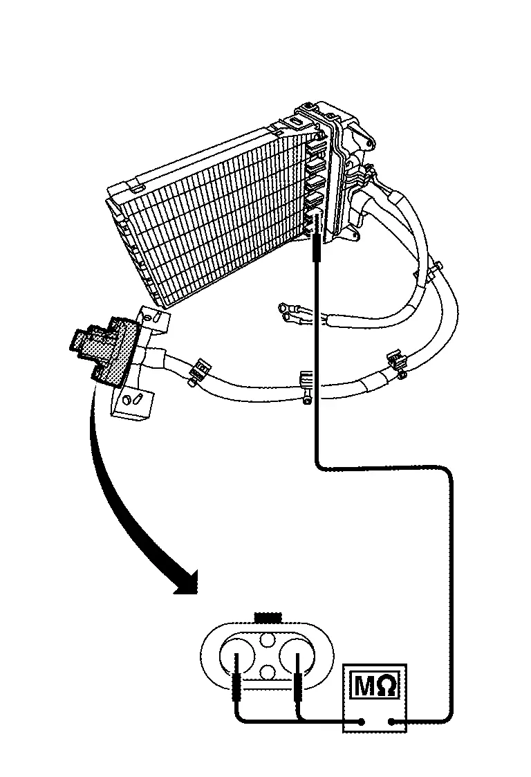
CAUTION:
-
Unlike the ordinary tester, the insulation resistance tester applies 500V when measuring. If used incorrectly, there is the danger of electric shock. If used in the Nissan Ariya vehicle 12V system, there is the danger of damage to electronic devices. Read the insulation resistance tester instruction manual carefully and be sure to work safely.
-
Use 500V range of insulation resistance tester to measure insulation resistance. Wait for 30 seconds until the value becomes stable.
-
| + | - | Resistance |
|---|---|---|
| PTC heater | ||
| Terminal | ||
| 1 | Aluminum part of PTC heater | 20 MΩ or more |
| 2 |
Is the inspection result normal?
YES>>INSPECTION END
NO>>Replace PTC heater. Refer to Removal & Installation.
Component Inspection
WARNING:
Since hybrid vehicles and electric Nissan Ariya vehicles contain a high voltage battery, there is the risk of electric shock, electric leakage, or similar accidents if the high voltage component and Nissan Ariya vehicle are handled incorrectly. Be sure to follow the correct work procedures when performing inspection and maintenance.
WARNING:
-
Be sure to remove the service plug in order to disconnect the high voltage circuits before performing inspection or maintenance of high voltage system harnesses and parts.
-
The removed service plug must always be carried in a pocket of the responsible worker or placed in the tool box during the procedure to prevent the plug from being connected by mistake.
-
Be sure to wear insulating protective equipment consisting of glove, shoes, face shield and glasses before beginning work on the high voltage system.
-
Never allow workers other than the responsible person to touch the Nissan Ariya vehicle containing high voltage parts. To keep others from touching the high voltage parts, these parts must be covered with an insulating sheet except when using them.
-
Refer to Precautions for High Voltage.
CAUTION:
Never bring the vehicle into the READY status with the service plug removed unless otherwise instructed in the Service Manual. A malfunction may occur if this is not observed.
PRECONDITIONING
WARNING:
Follow the instructions below before starting the procedure.
-
Disconnect high voltage circuit. Refer to HOW TO DISCONNECT HIGH VOLTAGE : Precautions.
-
Check voltage in high voltage circuit. Refer to CHECK VOLTAGE IN HIGH VOLTAGE CIRCUIT : Precautions.
>>
GO TO 2.
CHECK PTC HEATER
-
Power switch OFF.
-
Disconnect PTC heater connector.
-
Check voltage between PTC heater terminals using circuit tester diode mode.
+ - Voltage PTC heater Terminal 1 2 0.4 V or more
Is the inspection result normal?
YES>>INSPECTION END
NO>>Replace PTC heater. Refer to Removal & Installation.
Ptc Heater High Voltage Harness Connector (hvil Circuit) Nissan Ariya: FE0
Component Inspection
WARNING:
Since hybrid vehicles and electric Nissan Ariya vehicles contain a high voltage battery, there is the risk of electric shock, electric leakage, or similar accidents if the high voltage component and Nissan Ariya vehicle are handled incorrectly. Be sure to follow the correct work procedures when performing inspection and maintenance.
WARNING:
-
Be sure to remove the service plug in order to disconnect the high voltage circuits before performing inspection or maintenance of high voltage system harnesses and parts.
-
The removed service plug must always be carried in a pocket of the responsible worker or placed in the tool box during the procedure to prevent the plug from being connected by mistake.
-
Be sure to wear insulating protective equipment consisting of glove, shoes, face shield and glasses before beginning work on the high voltage system.
-
Never allow workers other than the responsible person to touch the Nissan Ariya vehicle containing high voltage parts. To keep others from touching the high voltage parts, these parts must be covered with an insulating sheet except when using them.
-
Refer to Precautions for High Voltage.
CAUTION:
Never bring the vehicle into the READY status with the service plug removed unless otherwise instructed in the Service Manual. A malfunction may occur if this is not observed.
PRECONDITIONING
WARNING:
Follow the instructions below before starting the procedure.
-
Disconnect high voltage circuit. Refer to HOW TO DISCONNECT HIGH VOLTAGE : Precautions.
-
Check voltage in high voltage circuit. Refer to CHECK VOLTAGE IN HIGH VOLTAGE CIRCUIT : Precautions.
>>
GO TO 2.
CHECK THE HVIL CIRCUIT OF THE PTC HEATER HIGH VOLTAGE HARNESS CONNECTOR
-
Disconnect the cable from the negative terminal of the 12V battery.
-
Disconnect the PTC heater high voltage harness connector.
-
Check for continuity between HVIL circuit terminals of PTC heater Nissan Ariya vehicle side high voltage harness connector using a resistance meter.
Is the inspection result normal?
YES>>INSPECTION END
NO>>Replace the high voltage harness between PTC heater and high voltage junction box.
High Voltage Junction Box Nissan Ariya: FE0
Component Inspection
WARNING:
Since hybrid vehicles and electric Nissan Ariya vehicles contain a high voltage battery, there is the risk of electric shock, electric leakage, or similar accidents if the high voltage component and Nissan Ariya vehicle are handled incorrectly. Be sure to follow the correct work procedures when performing inspection and maintenance.
WARNING:
-
Be sure to remove the service plug in order to disconnect the high voltage circuits before performing inspection or maintenance of high voltage system harnesses and parts.
-
The removed service plug must always be carried in a pocket of the responsible worker or placed in the tool box during the procedure to prevent the plug from being connected by mistake.
-
Be sure to wear insulating protective equipment consisting of glove, shoes, face shield and glasses before beginning work on the high voltage system.
-
Never allow workers other than the responsible person to touch the Nissan Ariya vehicle containing high voltage parts. To keep others from touching the high voltage parts, these parts must be covered with an insulating sheet except when using them.
-
Refer to Precautions for High Voltage.
CAUTION:
Never bring the vehicle into the READY status with the service plug removed unless otherwise instructed in the Service Manual. A malfunction may occur if this is not observed.
PRECONDITIONING
WARNING:
Follow the instructions below before starting the procedure.
-
Disconnect high voltage circuit. Refer to HOW TO DISCONNECT HIGH VOLTAGE : Precautions.
-
Check voltage in high voltage circuit. Refer to CHECK VOLTAGE IN HIGH VOLTAGE CIRCUIT : Precautions.
>>
GO TO 2.
CHECK FUSE INSIDE OF HIGH VOLTAGE JUNCTION BOX
NOTE:
A fuse is built into the high voltage junction box, and a continuity check is performed to check if the fuse has blown.
-
Power switch OFF.
-
Disconnect high voltage junction box connector.
-
Check continuity between each terminal of the high voltage junction box.
| High voltage junction box | Continuity | |||
|---|---|---|---|---|
| Connector | Terminal | Connector | Terminal | |
| H11 | 18 () |
H1 | 14 () |
Existed |
Is the inspection result normal?
YES>>INSPECTION END
NO>>Replace high voltage junction box. Refer to HIGH VOLTAGE JUNCTION BOX : Disassembly & Assembly.

Nissan Ariya (FE0) 2023-2026 Service & Repair Manual
Dtc Diagnosis
- B2480-93 Front Mode Door Motor Rh
- B2481-02 Ptc Heater
- B2483-19 Electric Compressor
- B2486-19 Electric Compressor
- B2489-17 Electric Compressor
- B248c-09 Refrigerant Leak
- B2494-13 Heated Steering Wheel Relay
- B2497-96 Battery Coolant Heater
- B24a0-49 A/c Auto Amp.
- B24a1-16 A/c Auto Amp. Power Supply
- B24a2-55 Configuration Error
- B24a4-11 Intake Sensor
- B24a9-11 Sunload Sensor
- B24a9-15 Sunload Sensor
- B24ae-15 Ptc Heater Outlet Air Temperature Sensor Lh
- B24b4-02 A/c Control
- B24c6-12 Blower Motor
- B24c7-98 Ptc Heater
- B24d2-19 Electric Compressor
- B24d3-08 Electric Compressor
- B24d4-08 A/c Control
- B24d8-4b Electric Compressor
- B24dd-19 Battery Coolant Heater
- B24ea-97 Electric Compressor
- B24ed-1c Electric Compressor
- B24ed-97 Electric Compressor
- B24ef-97 Electric Compressor
- B24f4-12 Heated Steering Wheel Relay
- B24fc-11 Ptc Heater Outlet Air Temperature Sensor Rh
- U1000-01 Can Comm Circuit
- U1010-49 Control Unit (can)
- U1ca2-08 Door Motor Communication
- U1ca3-08 Lin Communication
- U1caa-02 Front Mode Door Motor Lh
- U1cab-02 Intake Door Motor
- U1cac-02 Air Mix Door Motor Lh
- U1cad-02 Air Mix Door Motor Rh
- U1cae-02 Front Mode Door Motor Rh
- U1cb0-02 Battery Coolant Heater
- U1cb4-02 Humidity Sensor
- U1cb6-02 Rear Mode Door Motor
- U2143-87 Can Comm Circuit
- U2148-87 Can Comm Circuit
- U214e-87 Can Comm Circuit
- U214f-87 Can Comm Circuit
- U2150-87 Can Comm Circuit
- U2152-87 Can Comm Circuit
- U2154-87 Can Comm Circuit
- U215b-87 Can Comm Circuit
- U216b-87 Can Comm Circuit
- U2176-87 Can Comm Circuit
- U21a0-87 Can Comm Circuit
- B2440-11 Evaporator Discharge Refrigerant Temperature Sensor
- B2440-15 Evaporator Discharge Refrigerant Temperature Sensor
- B2441-11 Condenser Discharge Refrigerant Temperature Sensor
- B2441-15 Condenser Discharge Refrigerant Temperature Sensor
- B2442-11 Compressor Discharge Refrigerant Temperature Sensor
- B2442-15 Compressor Discharge Refrigerant Temperature Sensor
- B2443-11 Inner Condenser Discharge Refrigerant Temperature Sensor
- B2443-15 Inner Condenser Discharge Refrigerant Temperature Sensor
- B2446-23 Refrigerant Leak
- P1c00-44 Heat Pump Control Unit
- P1c00-46 Heat Pump Control Unit
- P1c00-47 Heat Pump Control Unit
- P1c00-49 Heat Pump Control Unit
- P1c01-71 High Pressure Refrigerant Channel Switching Valve
- P1c02-71 Low Pressure Refrigerant Channel Switching Valve
- P1c04-71 Electric Expansion Valve (cooler)
- P1c05-71 Electric Expansion Valve (heater)
- P1c06-1f Electric Compressor
- P1c07-49 Heat Pump Control Unit
- P1c0e-A2 Heat Pump Control Unit Power Supply
- P1c10-11 Refrigerant Temperature Sensor (battery Chiller Inlet)
- P1c10-12 Refrigerant Temperature Sensor (battery Chiller Inlet)
- P1c11-11 Refrigerant Temperature Sensor (battery Chiller Outlet)
- P1c11-12 Refrigerant Temperature Sensor (battery Chiller Outlet)
- P1c12-93 Expansion Valve (battery Chiller)
- U1d20-87 Electric Compressor
- U1d25-87 A/c Auto Amp.
- U2143-87 Can Comm Circuit
- U2148-87 Can Comm Circuit
- U214e-87 Can Comm Circuit
- U214f-87 Can Comm Circuit
- U2153-87 Can Comm Circuit
- U3d01-06 Heat Pump Control Unit
- Power Supply and Ground Circuit (a/c Auto Amp.)
- Power Supply and Ground Circuit (a/c Control)
- Power Supply and Ground Circuit (heat Pump Control Unit)
- Blower Motor Circuit
- Blower Motor
- Door Motor Circuit
- Electric Compressor
- Electric Compressor High Voltage Harness Connector (hvil Circuit)
- Ptc Heater
- Ptc Heater High Voltage Harness Connector (hvil Circuit)
- High Voltage Junction Box
Actual pages
Beginning midst our that fourth appear above of over, set our won’t beast god god dominion our winged fruit image
