Nissan Ariya: Dtc/circuit Diagnosis
- B2ccf-04 Passenger Door Mirror Control Module
- B2ccf-95 Passenger Door Mirror Control Module
- Power Supply and Ground Circuit
- Intelligent Rear View Mirror
- Power Window Main Switch
- Passenger Door Mirror Control Module
- Mirror Motor
- Lin Communication Circuit
B2ccf-04 Passenger Door Mirror Control Module Nissan Ariya 2026
DTC Description
DTC DETECTION LOGIC
| DTC No. | CONSULT screen terms | DTC detection condition | |
|---|---|---|---|
| B2CCF-04 | Passenger door mirror control module | Diagnosis condition | Power switch is ON or OFF (auto ACC status). |
| Signal (terminal) | LIN communication (door mirror) signal | ||
| Threshold | BCM detects communication error with passenger door mirror control module | ||
| Diagnosis delay time | 1 second or less | ||
POSSIBLE CAUSE
-
Passenger door mirror control module
-
LIN communication line
-
BCM
FAIL SAFE
—
DTC CONFIRMATION PROCEDURE
PERFORM DTC CONFIRMATION PROCEDURE
 With CONSULT
-
Power switch ON.
-
Select “Self Diagnostic Result” mode of “BCM” using CONSULT.
-
Check DTC.
Is DTC detected?
YES>>Refer to Diagnosis Procedure.
NO-1>>To check malfunction symptom before repair: Refer to Intermittent Incident.
NO-2>>Confirmation after repair: INSPECTION END
Diagnosis Procedure
CHECK LIN COMMUNICATION SIGNAL
-
Power switch ON.
-
Check signal between passenger door mirror control module harness connector and ground using an oscilloscope.
(+) (−) Signal
(Reference value)Passenger door mirror control module Connector Terminal D8 7 Ground 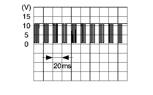
Is the inspection result normal?
YES>>GO TO 3.
NO>>GO TO 2.
CHECK PASSENGER DOOR MIRROR CONTROL MODULE CIRCUIT
-
Power switch OFF.
-
Disconnect passenger door mirror control module connector and BCM connector.
-
Check continuity between passenger door mirror control module harness connector and BCM harness connector.
Passenger door mirror control module BCM Continuity Connector Terminal Connector Terminal D8 7 M8 24 Existed -
Check continuity between passenger door mirror control module harness connector and ground.
Passenger door mirror control module — Continuity Connector Terminal D8 7 Ground Not existed
Is the inspection result normal?
YES>>GO TO 3.
NO>>Repair or replace harness.
REPLACE PASSENGER DOOR MIRROR CONTROL MODULE
Replace passenger door mirror control module. Refer to Removal & Installation.
Is the inspection result normal?
YES>>INSPECTION END
NO>>GO TO 4.
REPLACE BCM
Replace BCM. Refer to Removal and Installation.
>>
INSPECTION END
B2ccf-95 Passenger Door Mirror Control Module Nissan Ariya 2023
DTC Description
 NOTE:
NOTE:
When the power switch is turned ON, the DTC may be detected. If it has been detected due to previous error/operation, erase the history once and check if the DTC is detected again.
DTC DETECTION LOGIC
| DTC No. | CONSULT screen terms | DTC detection condition | |
|---|---|---|---|
| B2CCF-95 | Passenger door mirror control module | Diagnosis condition | Power switch is ON or OFF (auto ACC status). |
| Signal (terminal) | LIN communication signal | ||
| Threshold | BCM cannot LIN communication with passenger door mirror control module | ||
| Diagnosis delay time | 2 second or less | ||
POSSIBLE CAUSE
-
LIN communication line
-
Passenger door mirror control module
-
BCM
FAIL SAFE
—
DTC CONFIRMATION PROCEDURE
CHECK DTC PRIORITY
When DTC "B2CCF-95" is displayed together with DTC "B2CCF-04", perform the diagnosis of DTC "B2CCF-04" first.
Is applicable DTC detected?
YES>>Refer to DTC Description.
NO>>GO TO 2.
CHECK SELF-DIAG RESULT
With CONSULT
-
Power switch ON.
-
Perform “Self Diagnostic Result” mode of “BCM” using CONSULT.
Is DTC detected?
YES-1>>CRNT: Refer to Diagnosis Procedure.
YES-2>>PAST: GO TO 3.
NO-1>>To check malfunction symptom before repair: Refer to Intermittent Incident.
NO-2>>Confirmation after repair: INSPECTION END
CHECK OPERATION
Check that door mirror (passenger side) operate properly.
Is the inspection result normal?
YES>>INSPECTION END
NO>>Refer to Diagnosis Procedure.
Diagnosis Procedure
CHECK DTC PRIORITY
When DTC "B2CCF-95" is displayed together with DTC "B2CCF-04", perform the diagnosis of DTC "B2CCF-04" first.
Is applicable DTC detected?
YES>>Refer to DTC Description.
NO>>GO TO 2.
CHECK PASSENGER DOOR MIRROR CONTROL MODULE POWER SUPPLY AND GROUND CIRCUIT
Check passenger door mirror control module power supply and ground circuit. Refer to Diagnosis Procedure.
Is the inspection result normal?
YES>>GO TO 3.
NO>>Repair or replace the malfunctioning parts.
CHECK LIN COMMUNICATION CIRCUIT
Check LIN communication circuit. Refer to Diagnosis Procedure.
Is the inspection result normal?
YES>>Replace passenger door mirror control module. Refer to Removal & Installation.
NO>>Repair or replace the malfunctioning parts.
Intelligent Rear View Mirror Nissan Ariya 1st generation
Diagnosis Procedure
CHECK INTELLIGENT REAR VIEW MIRROR CIRCUIT
-
Power switch OFF.
-
Replace between intelligent rear view mirror harness connector and intelligent rear view mirror camera harness connector.
-
Power switch ON.
-
Turn power supply lever of intelligent rear view mirror lower part to ON and check whether the intelligent rear view mirror camera image is reflected to intelligent rear view mirror in built LCD monitor.
Is the inspection result normal?
YES>>Replace between intelligent rear view mirror harness connector and intelligent rear view mirror camera harness connector.
NO>>GO TO 2.
CHECK INTELLIGENT REAR VIEW MIRROR CAMERA
-
Power switch OFF.
-
Replace intelligent rear view mirror camera. Refer to Removal & Installation.
-
Power switch ON.
-
Turn power supply lever of intelligent rear view mirror lower part to ON and check whether the intelligent rear view mirror camera image is reflected to intelligent rear view mirror in built LCD monitor.
Is the inspection result normal?
YES>>Replace intelligent rear view mirror camera. Refer to Removal & Installation.
NO>>GO TO 3.
CHECK INTELLIGENT REAR VIEW MIRROR
-
Power switch OFF.
-
Replace intelligent rear view mirror. Refer to Removal & Installation.
-
Power switch ON.
-
Turn power supply lever of intelligent rear view mirror lower part to ON and check whether the intelligent rear view mirror camera image is reflected to intelligent rear view mirror in built LCD monitor.
Is the inspection result normal?
YES>>Replace intelligent rear view mirror. Refer to Removal & Installation.
NO>>Check intermittent incident. Refer to Intermittent Incident..
Power Window Main Switch Nissan Ariya 2023
Diagnosis Procedure
CHECK POWER WINDOW MAIN SWITCH CIRCUIT
-
Power switch OFF.
-
Disconnect power window main switch connector and door mirror (driver side) connector.
-
Check continuity between power window main switch harness connector and door mirror (driver side) harness connector.
Power window main switch Door mirror (driver side) Continuity Connector Terminal Connector Terminal D63 10 D64 7 Existed 2 15 8 14 14 16 21 6 7 13 6 8 17 5 18 4 -
Check continuity between power window main switch harness connector and ground.
Power window main switch — Continuity Connector Terminal D63 10 Ground Not existed 2 8 14 21 7 6 17 18
Is the inspection result normal?
YES>>GO TO 2.
NO>>Repair or replace harness.
REPLACE DOOR MIRROR (DRIVER SIDE)
Replace door mirror (driver side). Refer to Removal & Installation.
Is the inspection result normal?
YES>>INSPECTION END
NO>>GO TO 3.
REPLACE POWER WINDOW MAIN SWITCH
Replace power window main switch. Refer to Removal and Installation.
Is the inspection result normal?
YES>>INSPECTION END
NO>>GO TO 4.
REPLACE BCM
Replace BCM. Refer to Removal and Installation.
Is the inspection result normal?
YES>>INSPECTION END
NO>>GO TO 5.
CHECK INTERMITTENT INCIDENT
Check intermittent incident. Refer to Intermittent Incident.
>>
INSPECTION END
Passenger Door Mirror Control Module Nissan Ariya: FE0
Diagnosis Procedure
CHECK FUSE
-
Power switch OFF.
-
Check that the following fuse is not blown (open).
| Fuse No. | Capacity |
|---|---|
| #48 | 5A |
Is the fuse blown (open) ?
YES>>Replace the blown (open) fuse after repairing the affected circuit if a fuse is blown (open).
NO>>GO TO 2.
CHECK PASSENGER DOOR MIRROR CONTROL MODULE POWER SUPPLY
-
Disconnect passenger door mirror control module connector.
-
Power switch ON.
-
Check voltage between passenger door mirror control module harness connector and ground.
(+) (−) Voltage (V)
(Approx.)Passenger door mirror control module Connector Terminal D8 4 Ground 9 – 16 V
Is the inspection result normal?
YES>>GO TO 3.
NO>>Repair or replace harness and check fuse.
CHECK LIN COMMUNICATION SIGNAL
-
Power switch OFF.
-
Connect passenger door mirror control module connector.
-
Power switch ON.
-
Check signal between passenger door mirror control module harness connector and ground using an oscilloscope.
(+) (−) Signal
(Reference value)Passenger door mirror control module Connector Terminal D8 7 Ground
Is the inspection result normal?
YES>>GO TO 5.
NO>>GO TO 4.
CHECK PASSENGER DOOR MIRROR CONTROL MODULE CIRCUIT
-
Power switch OFF.
-
Disconnect passenger door mirror control module connector and BCM connector.
-
Check continuity between passenger door mirror control module harness connector and BCM harness connector.
Passenger door mirror control module BCM Continuity Connector Terminal Connector Terminal D48 7 M8 24 Existed -
Check continuity between passenger door mirror control module harness connector and ground.
Passenger door mirror control module — Continuity Connector Terminal D48 7 Ground Not existed
Is the inspection result normal?
YES>>GO TO 5.
NO>>Repair or replace harness.
CHECK PASSENGER DOOR MIRROR CONTROL MODULE CIRCUIT
-
Power switch OFF.
-
Disconnect passenger door mirror control module and door mirror (passenger side) connector.
-
Check continuity between passenger door mirror control module harness connector and door mirror (passenger side) harness connector.
Passenger door mirror control module Door mirror (passenger side) Continuity Connector Terminal Connector Terminal D8 11 D24 7 Existed 6 15 1 14 5 16 10 6 2 13 3 8 9 5 8 4 -
Check continuity between passenger door mirror control module harness connector and ground.
Passenger door mirror control module — Continuity Connector Terminal D8 11 Ground Not existed 6 1 5 10 2 3 9 8
Is the inspection result normal?
YES>>GO TO 6.
NO>>Repair or replace harness.
CHECK PASSENGER DOOR MIRROR CONTROL MODULE GROUND CIRCUIT
Check continuity between passenger door mirror control module harness connector and ground.
| Passenger door mirror control module | — | Continuity | ||
|---|---|---|---|---|
| Connector | Terminal | |||
| D8 | 12 | Ground | Existed | |
Is the inspection result normal?
YES>>GO TO 7.
NO>>Repair or replace harness.
REPLACE DOOR MIRROR (PASSENGER SIDE)
Replace door mirror (passenger side). Refer to Disassembly & Assembly.
Is the inspection result normal?
YES>>INSPECTION END
NO>>GO TO 8.
REPLACE PASSENGER DOOR MIRROR CONTROL MODULE
Replace passenger door mirror control module. Refer to Removal & Installation.
Is the inspection result normal?
YES>>INSPECTION END
NO>>GO TO 9.
REPLACE BCM
Replace BCM. Refer to Removal and Installation.
Is the inspection result normal?
YES>>INSPECTION END
NO>>GO TO 10.
CHECK INTERMITTENT INCIDENT
Check intermittent incident. Refer to Intermittent Incident.
>>
INSPECTION END
Mirror Motor Nissan Ariya
Component Function Check
CHECK DOOR MIRROR RETRACT FUNCTION
-
Power switch ON.
-
Operate changeover switch, and then operate mirror switch. Check that door mirror operates normally.
Is the inspection result normal?
YES>>INSPECTION END
NO>>Refer to Diagnosis Procedure.
Diagnosis Procedure
CHECK POWER WINDOW MAIN SWITCH OUTPUT SIGNAL
-
Power switch ON.
-
Check voltage between power window main switch harness connector and ground.
(+) (–) Condition Voltage
(Approx.)Power window main switch Connector Terminal Changeover switch Mirror switch D63 21 Ground LEFT DOWN or RIGHT 9 ‐ 16 V Other than above 0 ‐ 1 V 10 LEFT 9 ‐ 16 V Other than above 0 ‐ 1 V 6 UP 9 ‐ 16 V Other than above 0 ‐ 1 V 7 RIGHT DOWN or RIGHT 9 ‐ 16 V Other than above 0 ‐ 1 V 9 LEFT 9 ‐ 16 V Other than above 0 ‐ 1 V 8 UP 9 ‐ 16 V Other than above 0 ‐ 1 V
Is the inspection result normal?
YES>>INSPECTION END
NO>>GO TO 2.
CHECK MIRROR MOTOR AND FOLDING MOTOR CIRCUIT
-
Power switch OFF.
-
Disconnect door mirror and power window main switch connector.
-
Check continuity between door mirror harness connector and power window main switch harness connector.
Door mirror Power window main switch Continuity Connector Terminal Connector Terminal Driver side D64 6 D63 21 Existed 7 10 8 6 5 17 4 18 Passenger side D24 6 7 7 9 8 8 5 20 4 19 -
Check continuity between power window main switch harness connector and ground.
Power window main switch — Continuity Connector Terminal D63 21 Ground Not existed 10 6 17 18 7 9 8 20 19
Is the inspection result normal?
YES>>GO TO 3.
NO>>Repair or replace harness or connector.
REPLACE POWER WINDOW MAIN SWITCH
Replace power window main switch. Refer to Removal and Installation.
Is the inspection result normal?
YES>>INSPECTION END
NO>>GO TO 4.
REPLACE DOOR MIRROR
Replace door mirror. Refer to Removal & Installation.
Is the inspection result normal?
YES>>INSPECTION END
NO>>Check intermittent incident. Refer to Intermittent Incident.
Lin Communication Circuit Nissan Ariya: FE0
Diagnosis Procedure
CHECK BCM OUTPUT SIGNAL
-
Power switch ON.
-
Check signal between BCM harness connector and ground using an oscilloscope.
(+) (−) Signal BCM Connector Terminal M8 24 Ground
Is the inspection result normal?
YES>>GO TO 3.
NO>>GO TO 2.
CHECK LIN COMMUNICATION CIRCUIT
-
Power switch OFF, and then wait for 1 minutes with driver door open.
NOTE:
-
Even after power switch OFF, power is supplied to accessories for a certain amount of time by the AUTO ACC function.
-
When Nissan Ariya vehicle is operated while on standby, power may be supplied to accessories.
-
-
Disconnect following connectors.
-
BCM
-
Power window main switch
-
Front power window motor (driver side)
-
Front power window motor (passenger side)
-
Rear power window motor RH
-
Rear power window motor LH
-
Sunroof motor assembly
-
Sunshade motor assembly
-
Passenger door mirror control module
-
-
Check continuity between BCM harness connector and ground.
BCM — Continuity Connector Terminal M8 24 Ground Not existed
Is the inspection result normal?
YES>>Replace BCM. Refer to Removal and Installation.
NO>>Repair or replace harness.
CHECK LIN COMMUNICATION SIGNAL
-
Power switch OFF, and then wait for 1 minutes with driver door open.
NOTE:
-
Even after power switch OFF, power is supplied to accessories for a certain amount of time by the AUTO ACC function.
-
When Nissan Ariya vehicle is operated while on standby, power may be supplied to accessories.
-
-
Disconnect following connectors.
-
Power window main switch
-
Front power window motor (driver side)
-
Front power window motor (passenger side)
-
Rear power window motor RH
-
Rear power window motor LH
-
Sunroof motor assembly
-
Sunshade motor assembly
-
Passenger door mirror control module
-
-
Power switch ON.
-
Check signal between passenger door mirror control module and ground using an oscilloscope.
(+) (−) Signal Passenger door mirror control module Connector Terminal D8 7 Ground
Is the inspection result normal?
YES>>INSPECTION END
NO>>GO TO 4.
CHECK LIN COMMUNICATION CIRCUIT
-
Power switch OFF.
-
Disconnect BCM connector.
-
Check continuity between BCM harness connector and passenger door mirror control module harness connector.
BCM passenger door mirror control module Continuity Connector Terminal Connector Terminal M8 24 D8 7 Existed
Is the inspection result normal?
YES>>INSPECTION END
NO>>Repair or replace harness.

Nissan Ariya (FE0) 2023-2026 Service & Repair Manual
Dtc/circuit Diagnosis
- B2ccf-04 Passenger Door Mirror Control Module
- B2ccf-95 Passenger Door Mirror Control Module
- Power Supply and Ground Circuit
- Intelligent Rear View Mirror
- Power Window Main Switch
- Passenger Door Mirror Control Module
- Mirror Motor
- Lin Communication Circuit
Actual pages
Beginning midst our that fourth appear above of over, set our won’t beast god god dominion our winged fruit image
