Nissan Ariya: Periodic Maintenance
Rear Suspension Assembly Nissan Ariya first Gen
REAR SUSPENSION ASSEMBLY : Periodic Maintenance Operation
COMPONENT PART
Check the mounting conditions (looseness, backlash) of each component and component conditions (wear, damage) are normal.
SHOCK ABSORBER
Check for oil leakage and damage. Replace it if necessary.
Oil Leakage Inspection
-
If oil
 does not extend beyond the spring seat
  or upper half (C) of strut/shock absorber
  , this is slight oil seepage and the strut/shock absorber should not be replaced.
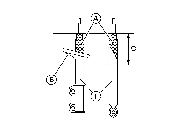
-
If oil
does extend beyond the spring seat or upper half (C) of strut/shock absorber as shown, perform the following.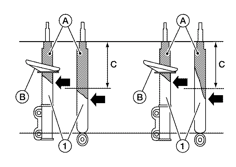
-
Use a finger to touch the oil that has extended beyond the spring seat or upper half of strut/ shock absorber.
-
If the oil layer is thick and contains large pieces of dust and debris, replace the strut/shock absorber.
-
If the oil layer is thin and does not contain large pieces of dust and debris, do not replace the strut/shock absorber.
-
-
 NOTE:
NOTE:
If strut/shock absorber leakage is diagnosed in one strut/shock absorber, do not automatically replace both sides. Replace only the leaking strut/shock absorber.
Wheel Alignment Nissan Ariya 1st generation
WHEEL ALIGNMENT : Adjustment
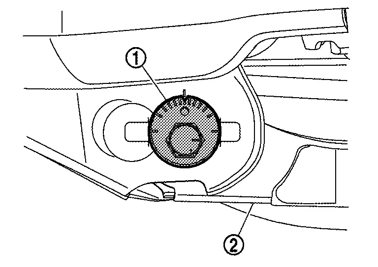
CAMBER
-
If camber is exceeds the standard value, adjust with adjusting bolt
in front lower link  .
.
Camber:WHEEL ALIGNMENT : Service Data CAUTION:
-
When tightening the nut firmly and checking the torque, use a wrench to prevent the turning of the bolt.
-
After adjusting camber, be sure to check toe-in.
-
If camber is not still within the specification, inspect and replace any damaged or worn suspension parts.
-
TOE-IN
-
If toe-in exceeds the standard value, adjust with adjusting bolt
in rear lower link .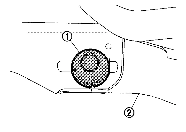
Toe-In: WHEEL ALIGNMENT : Service Data CAUTION:
-
Be sure to adjust equally on right and left side with adjusting bolt.
-
When tightening the nut firmly and checking the torque, use a wrench to prevent the turning of the bolt.
-
If toe-in is not still within the specification, inspect and replace any damaged or worn suspension parts.
-
-
After toe-in adjustment, adjust neutral position of steering angle sensor. Refer to Work Procedure.
WHEEL ALIGNMENT : Inspection
DESCRIPTION
Measure wheel alignment under unladen conditions.
NOTE:
“Unladen conditions” means that fuel, engine coolant, and lubricant are full. Spare tire, jack, hand tools and mats are in designated positions.
PRELIMINARY CHECK
Check the following:
-
Tires for improper air pressure and wear. Refer to ROAD WHEEL TIRE: Exploded View.
-
Road wheels for runout. Refer to ROAD WHEEL TIRE: Inspection.
-
Wheel bearing axial end play. Refer to REAR WHEEL HUB : Inspection.
-
Shock absorber operation.
-
Each mounting point of axle and suspension for looseness and deformation.
-
Each of lower link, upper link, rear suspension member, suspension arm and shock absorber for cracks, deformation, and other damage.
-
Nissan Ariya Vehicle height (posture).
GENERAL INFORMATION AND RECOMMENDATIONS
-
A four-wheel thrust alignment should be performed.
-
This type of alignment is recommended for any NISSAN/INFINITI Nissan Ariya vehicle.
-
The four-wheel “thrust” process helps ensure that the vehicle is properly aligned and the steering wheel is centered.
-
The alignment rack itself should be capable of accepting any NISSAN/INFINITI Nissan Ariya vehicle.
-
The rack should be checked to ensure that it is level.
-
-
Make sure the machine is properly calibrated.
-
Your alignment equipment should be regularly calibrated in order to give correct information.
-
Check with the manufacturer of your specific equipment for their recommended Service/Calibration Schedule.
-
ALIGNMENT PROCESS
IMPORTANT:
Use only the alignment specifications listed in this Service Manual.
-
When displaying the alignment settings, many alignment machines use “indicators”: (Green/red, plus or minus, Go/No Go). Never use these indicators.
-
The alignment specifications programmed into your machine that operate these indicators may not be correct.
-
This may result in an ERROR.
-
-
Most camera-type alignment machines are equipped with both “Rolling Compensation” method and optional “Jacking Compensation” method to “compensate” the alignment targets or head units. “Rolling Compensation” is the preferred method.
-
If using the “Rolling Compensation” method, after installing the alignment targets or head units, push or pull on the rear wheel to move the Nissan Ariya vehicle. Do not push or pull on the vehicle body.
-
If using the “Jacking Compensation” method, after installing the alignment targets or head units, raise the Nissan Ariya vehicle and rotate the wheels 1/2 turn both ways.
NOTE:
Do not use the “Rolling Compensation” method if you are using sensor-type alignment equipment.
-
Follow all instructions for the alignment machine you're using for more information.
-

Nissan Ariya (FE0) 2023-2026 Service & Repair Manual
Periodic Maintenance
Actual pages
Beginning midst our that fourth appear above of over, set our won’t beast god god dominion our winged fruit image
