Nissan Ariya: Removal and Installation
- Rear Shock Absorber
- Coil Spring
- Radius Rod
- Front Lower Link
- Rear Lower Link
- Rear Stabilizer
- Suspension Arm
- Rear Suspension Member
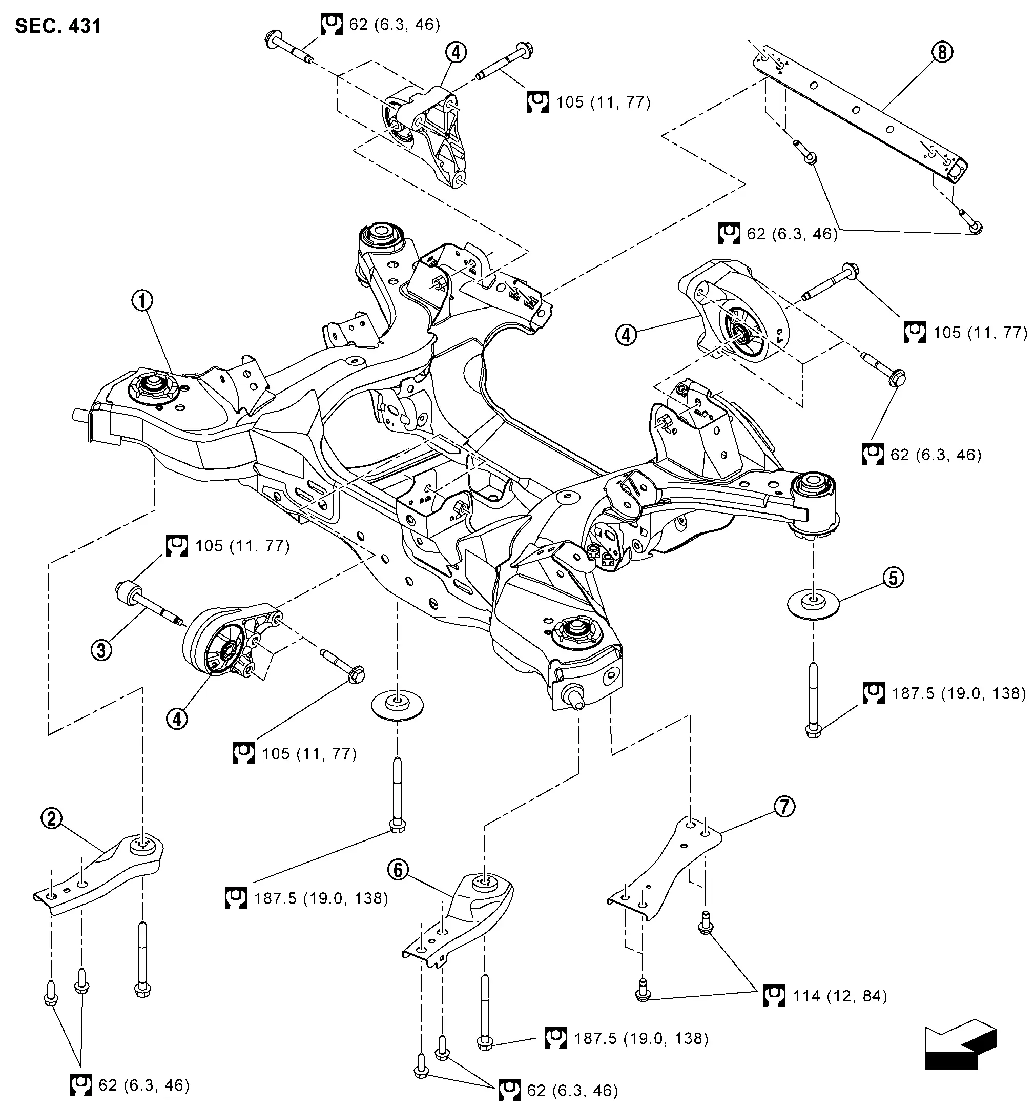
Rear Shock Absorber Nissan Ariya: FE0
REAR SHOCK ABSORBER : Exploded View
FOR 2WD MODELS
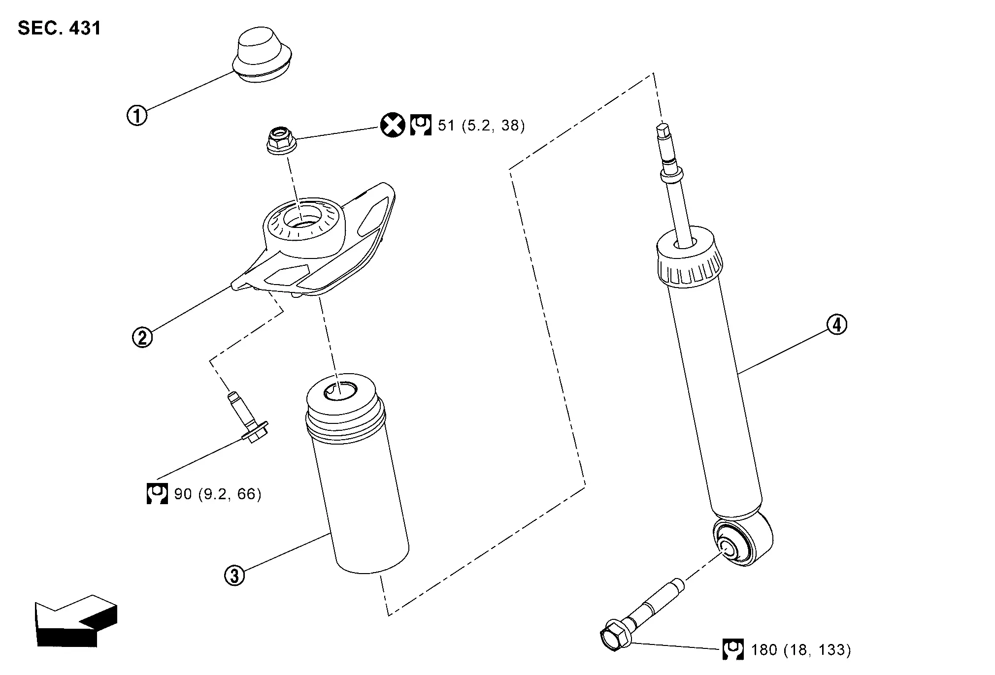
 |
Cap |  |
Shock absorber mounting bracket |  |
Bound bumper |
 |
Shock absorber | ||||
 |
: Nissan Ariya Vehicle front | ||||
 |
: N·m (kg-m, ft-lb) | ||||
 |
: Always replace after every disassembly. | ||||
FOR 4WD MODELS
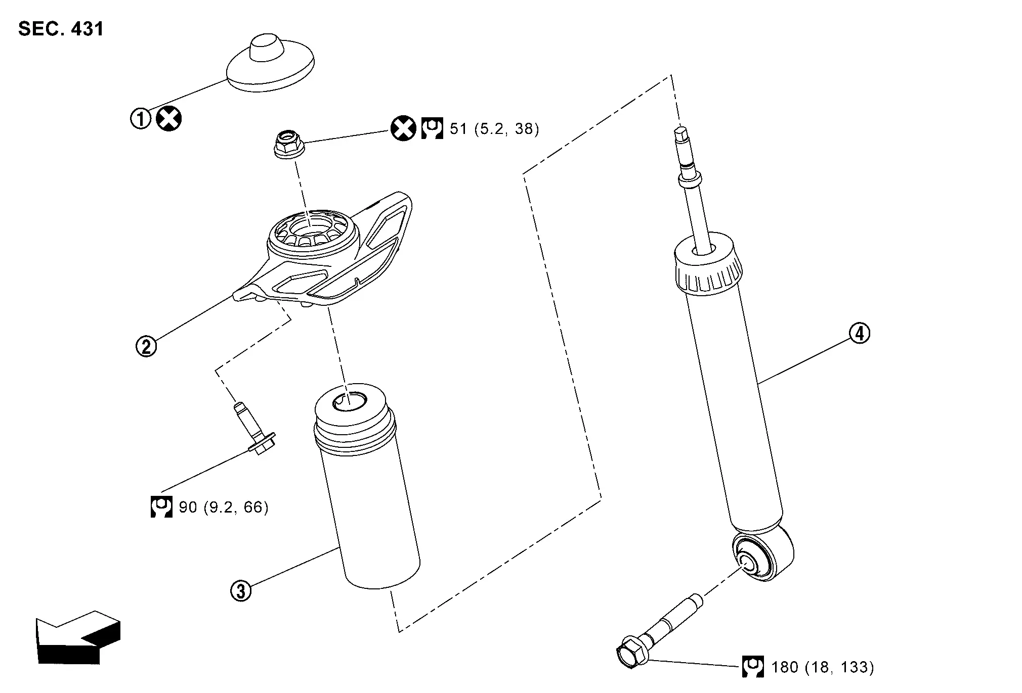
|
Cap | |
Shock absorber mounting bracket | |
Bound bumper |
|
Shock absorber | ||||
|
: Nissan Ariya Vehicle front | ||||
|
: N·m (kg-m, ft-lb) | ||||
|
: Always replace after every disassembly. | ||||
REAR SHOCK ABSORBER : Removal & Installation
REMOVAL
Remove tires. Refer to ROAD WHEEL TIRE : Removal and Installation.
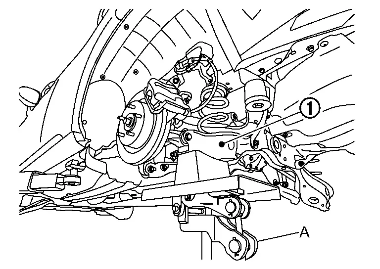
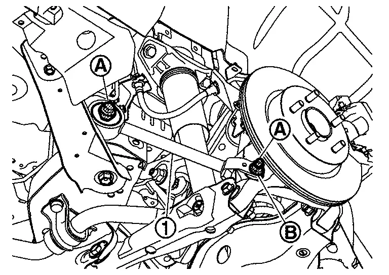
Set jack (A) under front lower link.
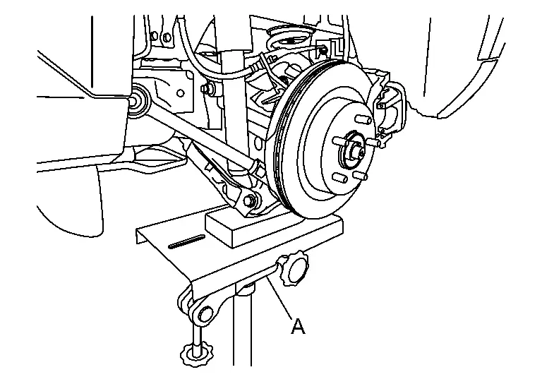
CAUTION:
-
Check the stable condition when using a jack.
-
Never damage front lower link with a jack.
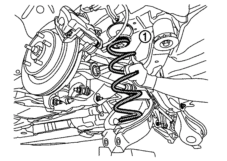
Remove shock absorber mounting bolt  (lower side).
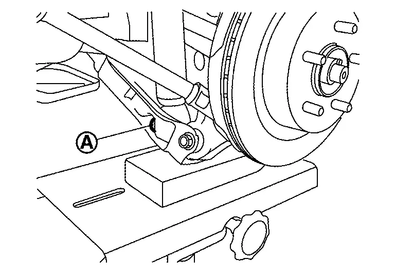
Slowly lower jack, separate shock absorber from front lower link.
CAUTION:
Operate jack while checking its supporting status.
Remove mounting bolt of shock absorber and then remove shock absorber.
Remove cap from mounting bracket, if necessary.
Perform inspection after removal. Refer to REAR SHOCK ABSORBER : Inspection.
INSTALLATION
Note the following, and install in the reverse order of removal.
-
Perform final tightening of fixing parts at installation position (rubber bushing) to the Nissan Ariya vehicle , under unladen conditions with tires on level ground.
-
Perform inspection after installation. Refer to REAR SHOCK ABSORBER : Inspection.
-
After replacing the shock absorber, always follow the disposal procedure to discard the shock absorber. Refer to REAR SHOCK ABSORBER : Disposal.
REAR SHOCK ABSORBER : Disassembly & Assembly
DISASSEMBLY
CAUTION:
-
Never damage shock absorber piston rod when removing components from shock absorber.
-
When fixing shock absorber with a vise, wrap a shop cloth around lower side of shock absorber to protect from damage. Never set the cylindrical part of shock absorber with a vise.
-
When installing piston rod lock nut
, secure the piston rod tip to prevent piston rod from turning.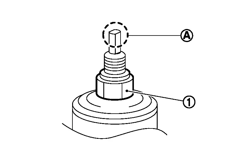
-
Perform inspection after disassembly. Refer to REAR SHOCK ABSORBER : Inspection.
ASSEMBLY
Note the following, and install in the reverse order of removal.
-
Never damage shock absorber piston rod when removing components from shock absorber.
-
When fixing shock absorber with a vise, wrap a shop cloth around lower side of shock absorber to protect from damage. Never set the cylindrical part of shock absorber with a vise.
-
When installing piston rod lock nut
, secure the piston rod tip to prevent piston rod from turning.CAUTION:
Never reuse piston rod lock nut.
-
Perform inspection after assembly. Refer to REAR SHOCK ABSORBER : Inspection.
REAR SHOCK ABSORBER : Inspection
INSPECTION AFTER REMOVAL
Check rear shock absorber for deformation, crack, and damage.
INSPECTION AFTER DISASSEMBLY
Mounting Bracket
Check mounting bracket for deformation, crack and damage. Replace it if necessary.
Bound Bumper
Check bound bumper bracket for deformation, crack and damage. Replace it if necessary.
Shock Absorber
Check the following item of shock absorber, and replace it if necessary.
-
Shock absorber and bushing for deformation, cracks, and other damage.
-
Piston rod for damage, uneven wear, and distortion.
-
Oil leakage
INSPECTION AFTER ASSEMBLY
Check shock absorber for operation. Replace it if necessary.
INSPECTION AFTER INSTALLATION
Check wheel alignment. Refer to Wheel Alignment: Inspection.
REAR SHOCK ABSORBER : Disposal
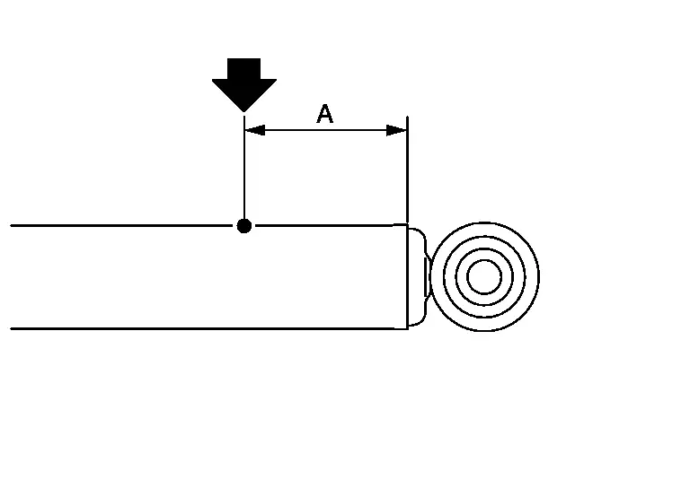
Set shock absorber horizontally to the ground with the piston rod fully extracted.
Drill 2 – 3 mm (0.08 – 0.12 in) hole at the position ( ) from top as shown in the figure to release gas gradually.
CAUTION:
-
Wear eye protection (safety glasses).
-
Wear gloves.
-
Be careful with metal chips or oil blown out by the compressed gas.
 NOTE:
NOTE:
-
Drill vertically in this direction show by arrow(
 ).
). -
Directly drill in the outer tube avoiding brackets.
-
The gas is clear, colorless, odorless, and harmless.
| Dimension A | : 20 – 30 mm (0.79 – 1.18 in) |
Drain oil from drilled hole by moving the piston rod several times.
CAUTION:
Dispose of drained oil according to the law and local regulations.
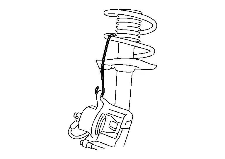
Coil Spring Nissan Ariya 1st generation
COIL SPRING : Exploded View
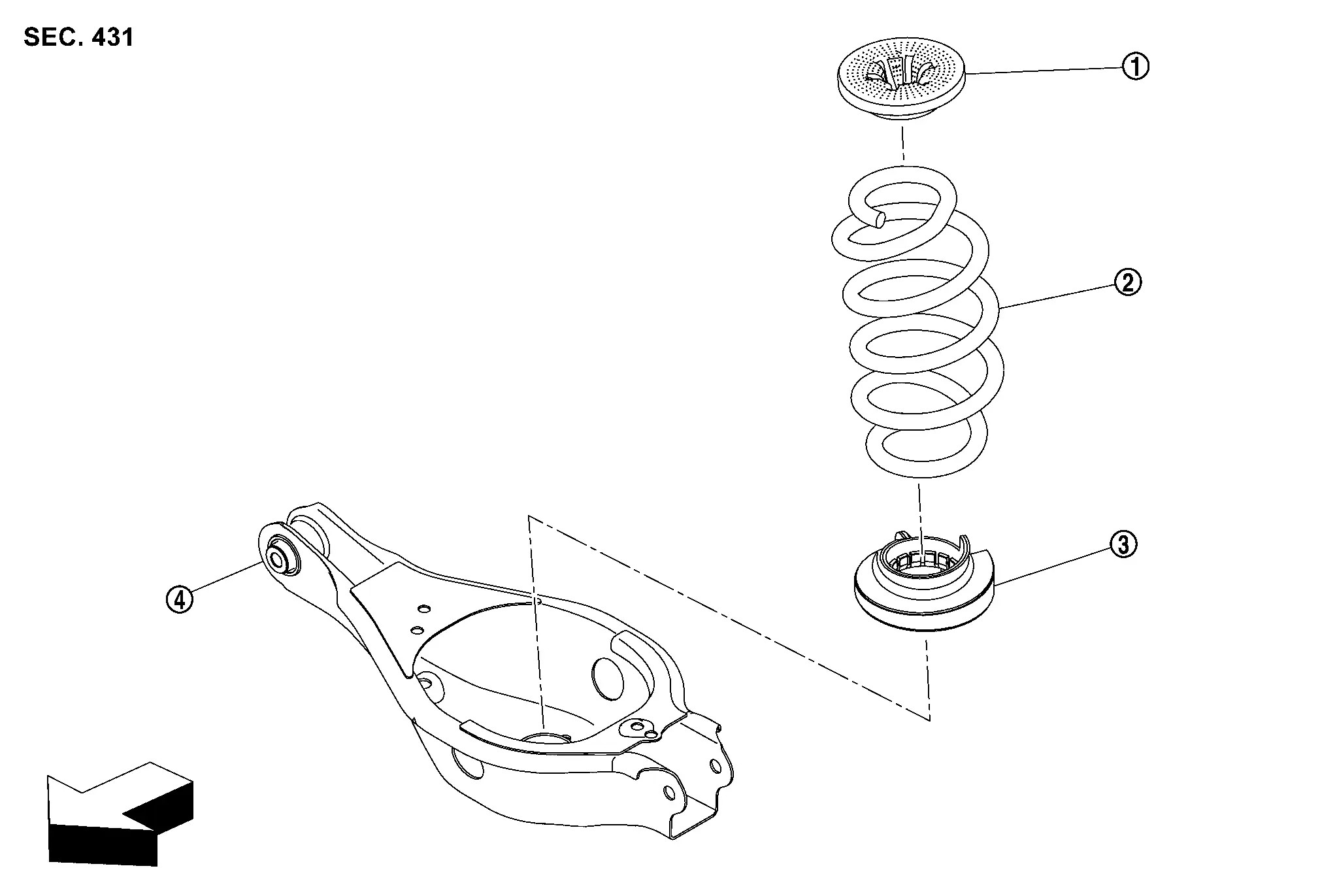
|
Upper rubber seat | |
Coil spring | |
Lower rubber seat |
|
Rear lower link | ||||
|
: Nissan Ariya Vehicle front | ||||
COIL SPRING : Removal & Installation
REMOVAL
Remove tires. Refer to ROAD WHEEL TIRE: Exploded View.
Remove rear diffuser front. Refer to Removal and Installation.
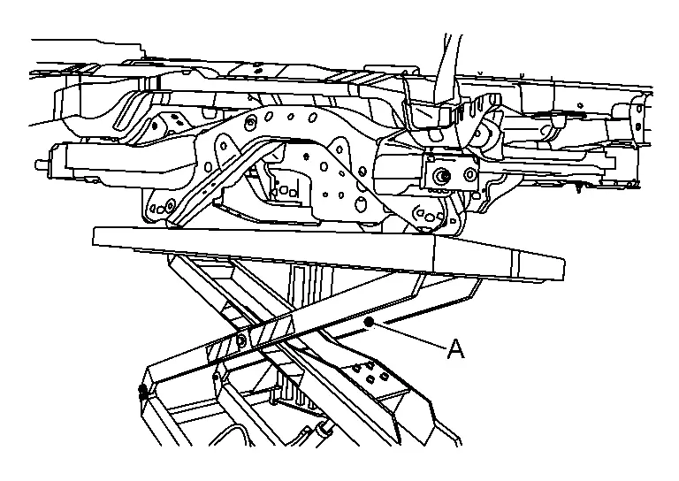
Set jack (A) to rear lower link .
CAUTION:
-
Never damage the rear lower link with a jack.
-
Check the stable condition when using a jack.
Loosen rear lower link mounting bolt and nut (rear suspension member side).
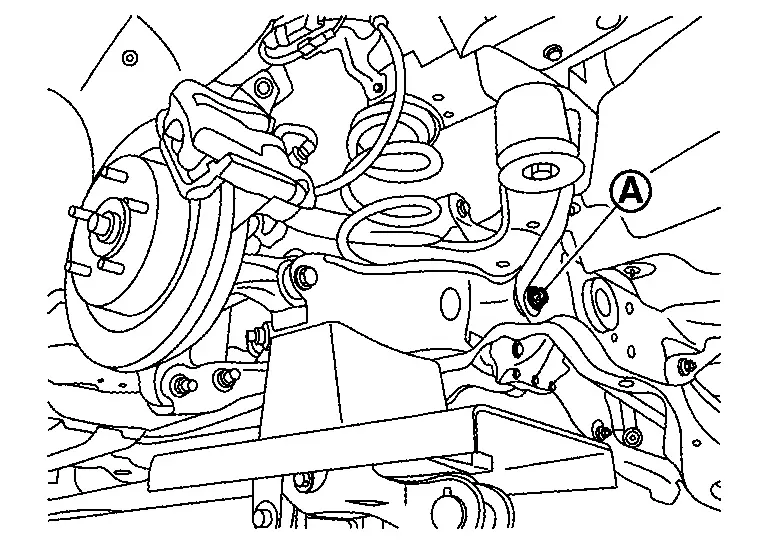
Remove mounting bolt and nut of rear lower link (axle housing side).
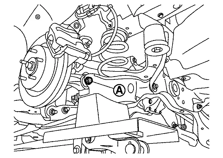
Slowly lower jack, remove upper rubber seat and coil spring .
CAUTION:
Operate jack while checking its supporting status.
Remove lower rubber seat from rear lower link.
Perform inspection after removal. Refer to COIL SPRING : Inspection.
INSTALLATION
Note the following, and install in the reverse order of removal.
-
Install lower rubber seat
by aligning its protrusion with the hole  of rear lower link .
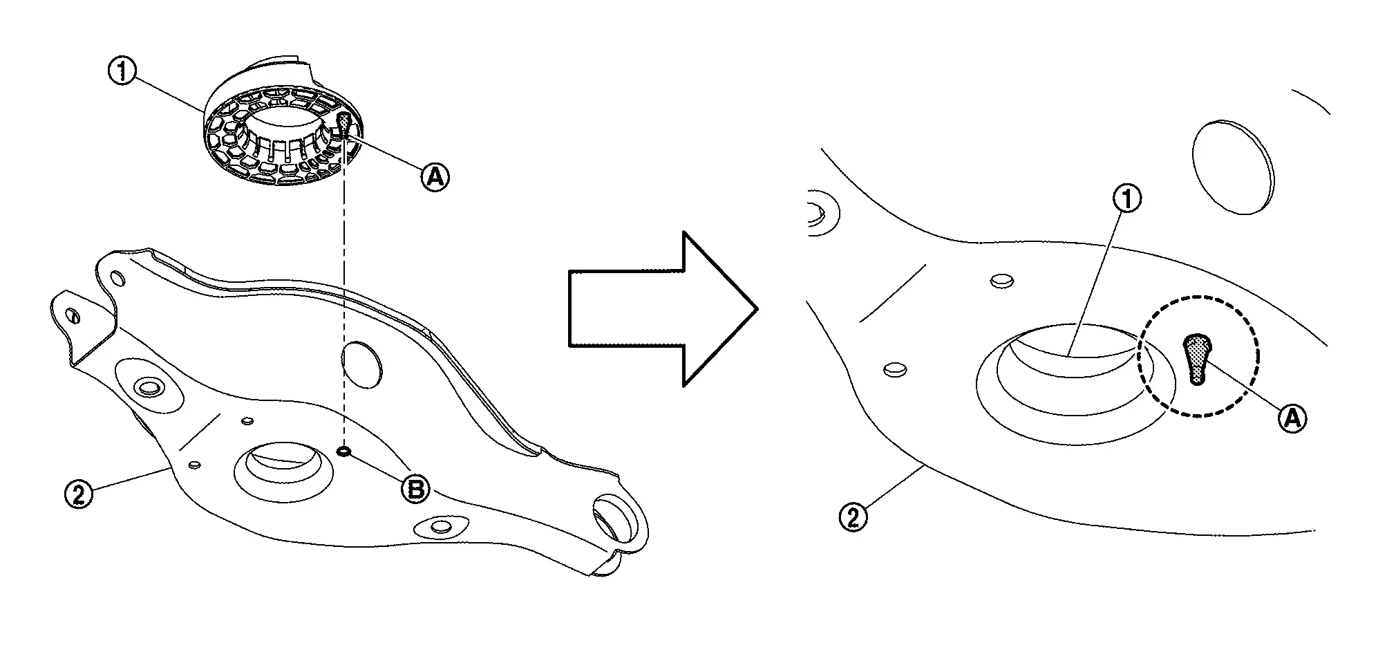
CAUTION:
The protrusion of lower rubber seat must securely be inserted into the hole of rear lower link.
-
Install coil spring by aligning lower end of coil spring
with lower rubber seat as shown in the figure.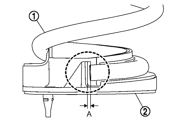
Dimension (A) : 5 mm (0.20 in) or less CAUTION:
Set coil spring by aligning paint mark
with the position from the bottom end of the coil spring shown in the figure.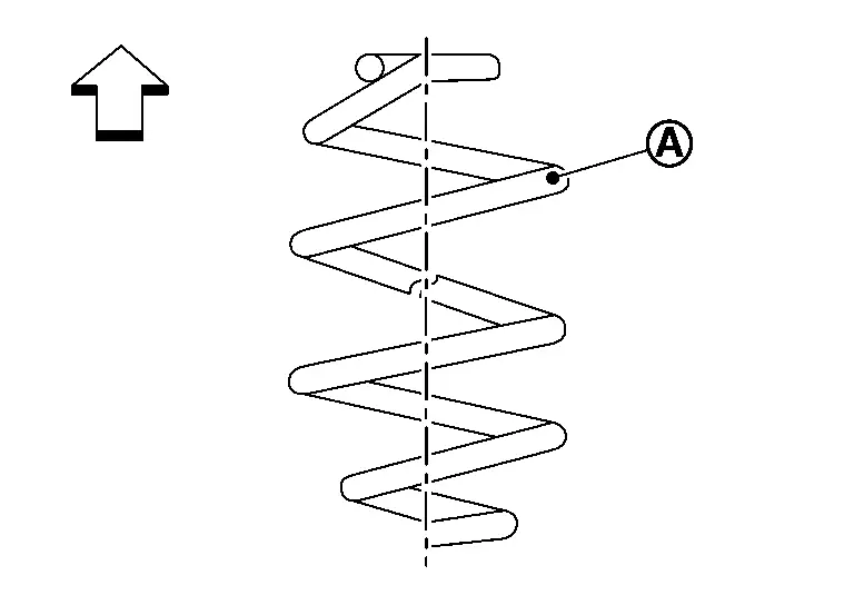
: Upper side : 4.5 turns -
Perform final tightening of fixing parts at installation position (rubber bushing) to the Nissan Ariya vehicle, under unladen conditions with tires on level ground.
-
Perform inspection after installation. Refer to COIL SPRING : Inspection.
COIL SPRING : Inspection
INSPECTION AFTER ASSEMBLY
Check the rear lower link, upper rubber seat, lower rubber seat, and coil spring for deformation, cracks, damage. Replace it if necessary.
INSPECTION AFTER INSTALLATION
Check wheel alignment. Refer to Wheel Alignment: Inspection.
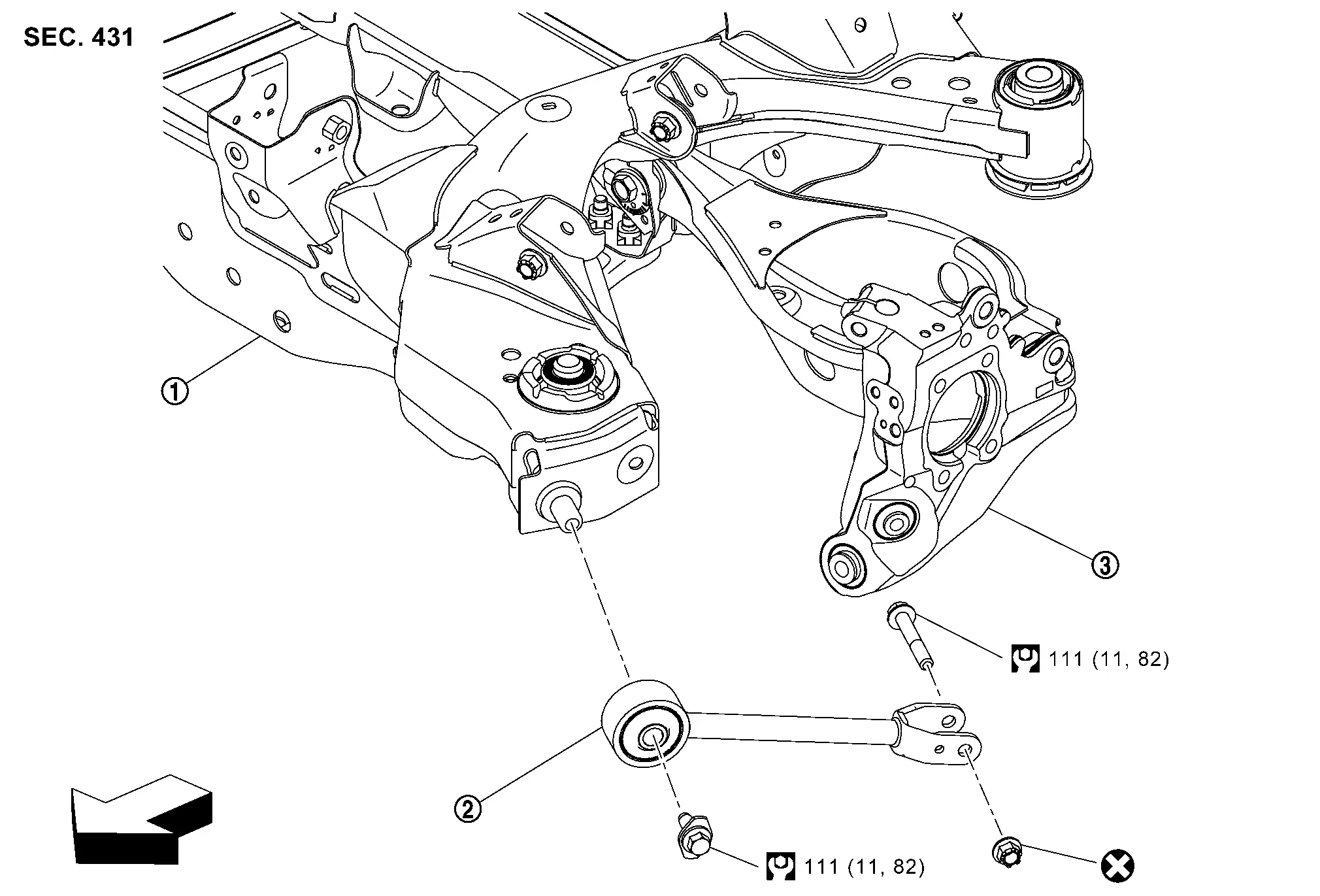
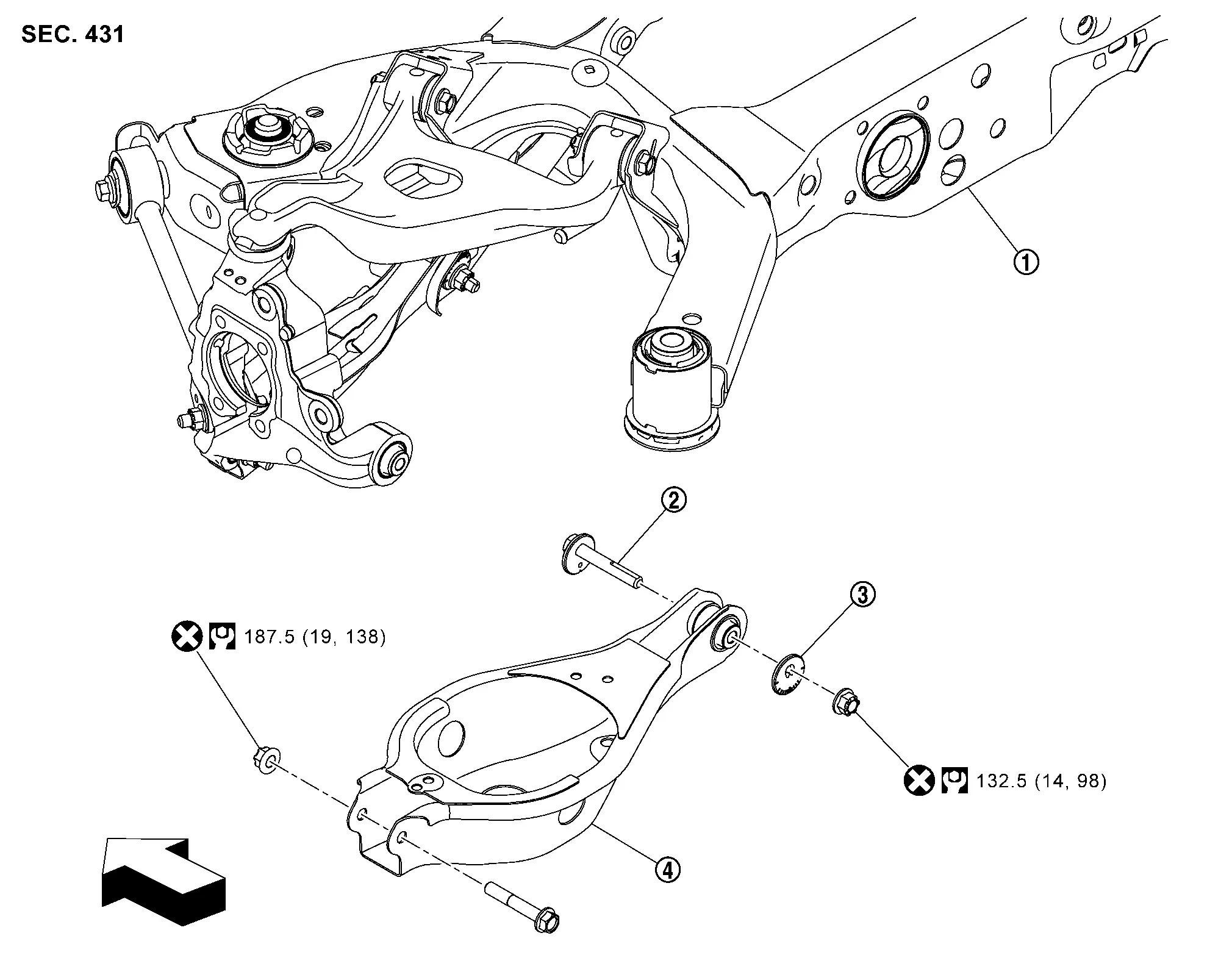
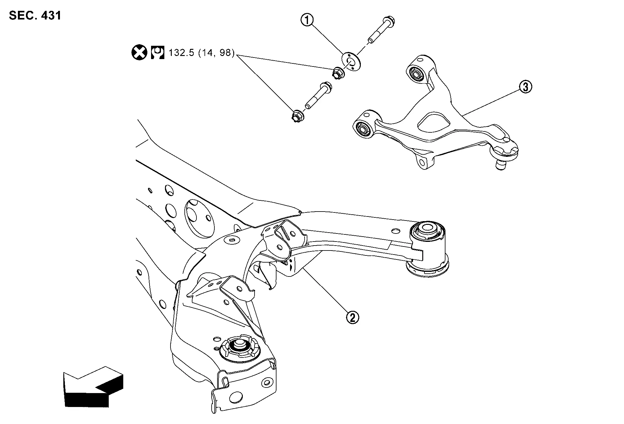
Radius Rod Nissan Ariya SUV
RADIUS ROD : Exploded View
FOR 2WD MODELS
|
Rear suspension member | |
Radius rod | |
Axle housing |
|
: Nissan Ariya Vehicle front | ||||
|
: N·m (kg-m, ft-lb) | ||||
|
: Always replace after every disassembly. | ||||
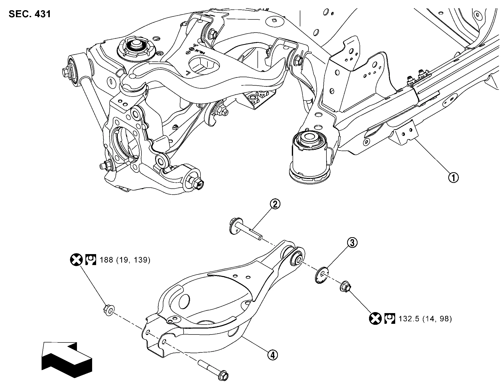
FOR 4WD MODELS
|
Rear suspension member | |
Radius rod | |
Axle housing |
|
: Nissan Ariya Vehicle front | ||||
|
: N·m (kg-m, ft-lb) | ||||
|
: Always replace after every disassembly. | ||||
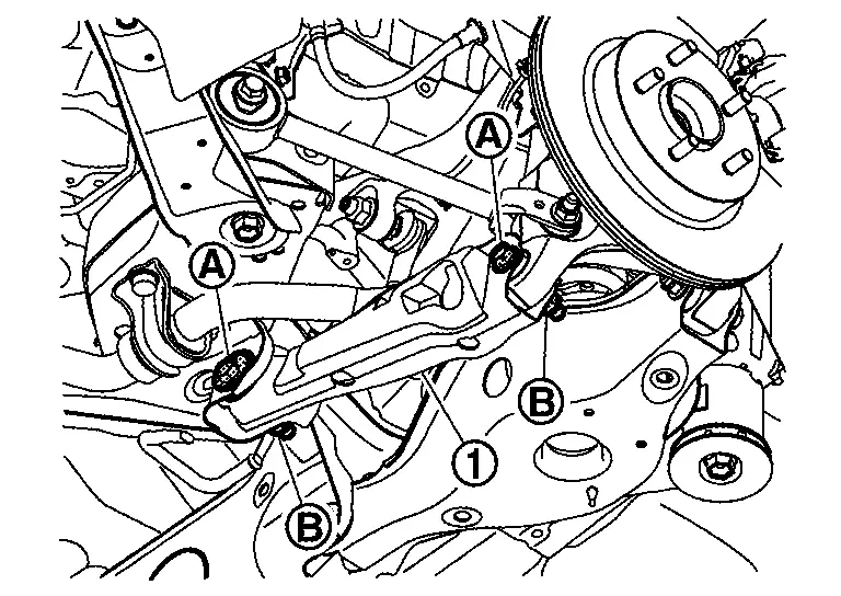
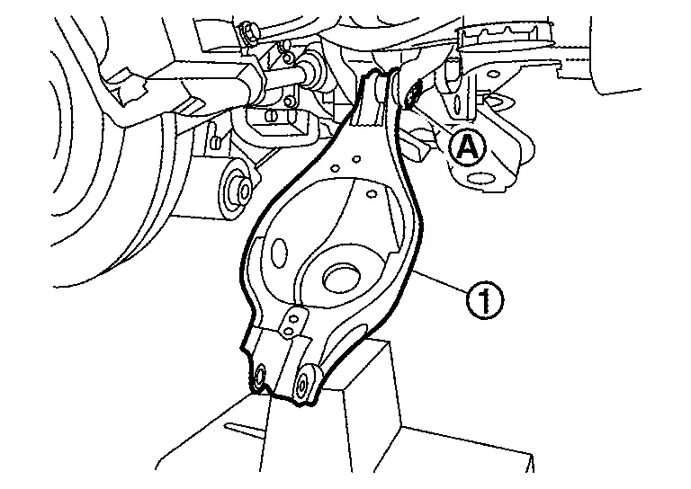
RADIUS ROD : Removal & Installation
REMOVAL
Remove tires. Refer to ROAD WHEEL TIRE : Removal and Installation.
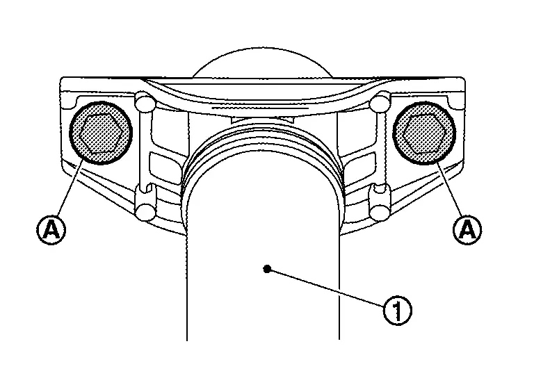
Set jack to axle housing, and raise jack until the position where bolt of axle housing side can be pulled out.
Remove radius rod mounting bolt and nut .
Remove radius rod. Refer to RADIUS ROD : Exploded View.
Perform inspection after installation. Refer to RADIUS ROD : Inspection.
INSTALLATION
Note the following, and install in the reverse order of removal.
-
Perform final tightening of fixing parts at installation position (rubber bushing) to the Nissan Ariya vehicle, under unladen conditions with tires on level ground.
-
For parts unable to reuse, Refer to RADIUS ROD : Exploded View.
-
Perform inspection after installation. Refer to RADIUS ROD : Inspection.
RADIUS ROD : Inspection
INSPECTION AFTER REMOVAL
Check radius rod and bushing for deformation, cracks, and damage. Replace it if necessary.
INSPECTION AFTER INSTALLATION
Check wheel alignment. Refer to Wheel Alignment: Inspection.
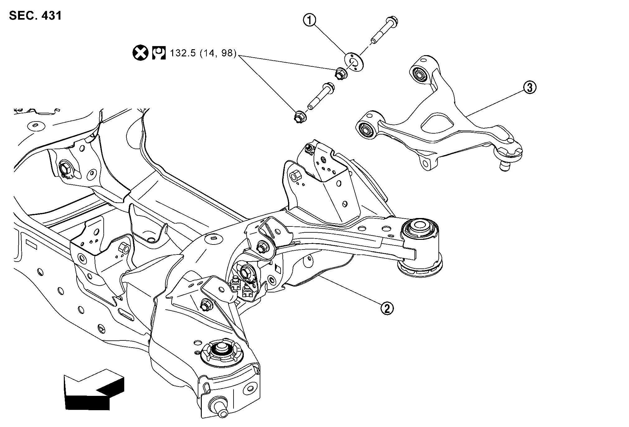
Front Lower Link Nissan Ariya 2023
FRONT LOWER LINK : Exploded View
FOR 2WD MODELS
|
Rear suspension member | |
Eccentric disk | |
Adjusting bolt |
|
Front lower link |  |
Axle housing | ||
|
: Nissan Ariya Vehicle front | ||||
|
: N·m (kg-m, ft-lb) | ||||
|
: Always replace after every disassembly. | ||||
FOR 4WD MODELS
|
Rear suspension member | |
Eccentric disk | |
Adjusting bolt |
|
Front lower link | |
Axle housing | ||
|
: Nissan Ariya Vehicle front | ||||
|
: N·m (kg-m, ft-lb) | ||||
|
: Always replace after every disassembly. | ||||
FRONT LOWER LINK : Removal & Installation
REMOVAL
Remove tires. Refer to ROAD WHEEL TIRE : Removal and Installation.
Set jack to axle housing.
Remove rear diffuser front. Refer to Removal and Installation.
Remove rear shock absorber. REAR SHOCK ABSORBER : Removal and Installation.
Remove rear stabilizer. Refer to REAR STABILIZER : Removal and Installation.
Remove front lower link mounting bolts and nuts .
Remove front lower link from Nissan Ariya vehicle.
Perform inspection after removal. Refer to FRONT LOWER LINK : Inspection.
INSTALLATION
Note the following, and install in the reverse order of removal.
-
Perform final tightening of fixing parts at installation position (rubber bushing) to the Nissan Ariya vehicle , under unladen conditions with tires on level ground.
-
For non-reusable parts, Refer to FRONT LOWER LINK : Exploded View.
-
Perform inspection after installation. Refer to FRONT LOWER LINK : Inspection.
FRONT LOWER LINK : Inspection
INSPECTION AFTER REMOVAL
Check front lower link and bushing for deformation, crack, and damage. Replace it if necessary.
INSPECTION AFTER INSTALLATION
Check wheel alignment. Refer to Wheel Alignment: Inspection.
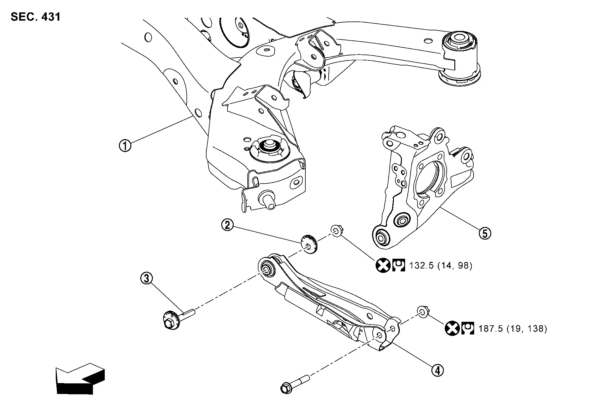
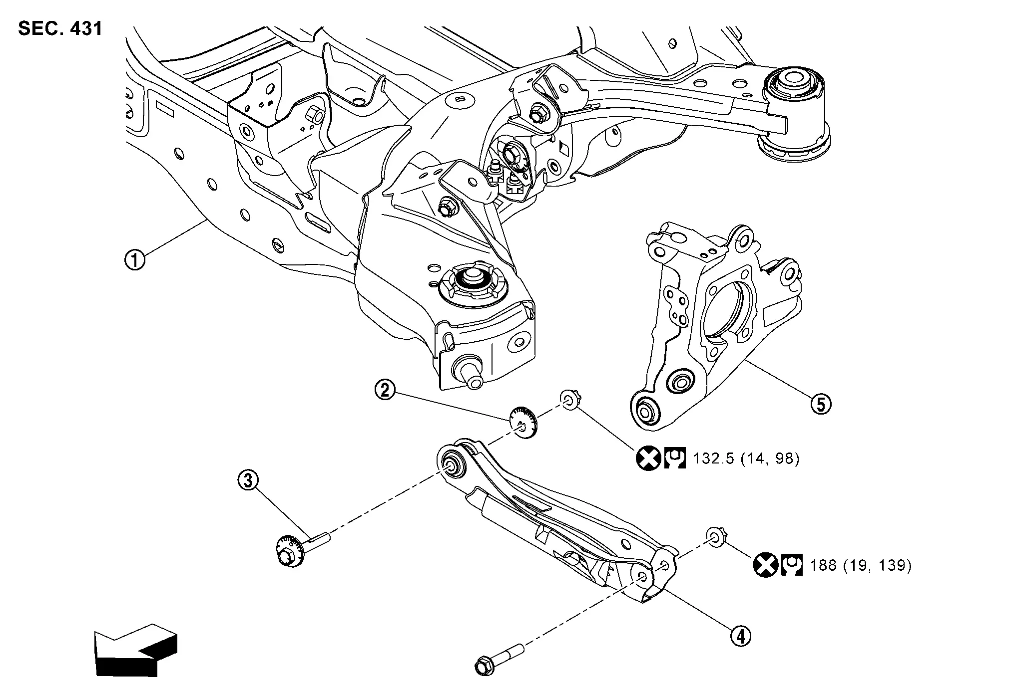
Rear Lower Link Nissan Ariya first Gen
REAR LOWER LINK : Exploded View
FOR 2WD MODELS
|
Rear suspension member | |
Adjusting bolt | |
Eccentric disk |
|
Rear lower link | ||||
|
: Nissan Ariya Vehicle front | ||||
|
: N·m (kg-m, ft-lb) | ||||
|
: Always replace after every disassembly. | ||||
FOR 4WD MODELS
|
Rear suspension member | |
Adjusting bolt | |
Eccentric disk |
|
Rear lower link | ||||
|
: Nissan Ariya Vehicle front | ||||
|
: N·m (kg-m, ft-lb) | ||||
|
: Always replace after every disassembly. | ||||
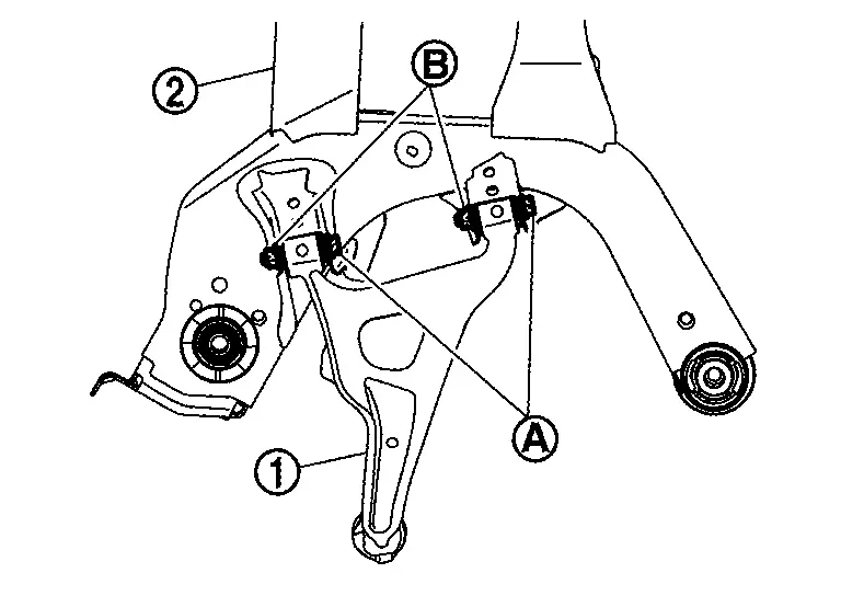
REAR LOWER LINK : Removal & Installation
REMOVAL
Remove rear coil spring. Refer to COIL SPRING : Removal and Installation.
Remove front lower link mounting bolt .
Perform inspection after removal. Refer to COIL SPRING : Inspection.
INSTALLATION
Note the following, and install in the reverse order of removal.
-
Perform final tightening of fixing parts at installation position (rubber bushing) to the Nissan Ariya vehicle , under unladen conditions with tires on level ground.
-
For parts unable to reuse, Refer to REAR LOWER LINK : Exploded View.
-
Perform inspection after installation. Refer to REAR LOWER LINK : Inspection.
REAR LOWER LINK : Inspection
INSPECTION AFTER REMOVAL
Check lower link and bushing for deformation, cracks, and damage. Replace it if necessary.
INSPECTION AFTER INSTALLATION
Check wheel alignment. Refer to Wheel Alignment: Inspection.
Rear Stabilizer Nissan Ariya: FE0
REAR STABILIZER : Exploded View
FOR 2WD MODELS
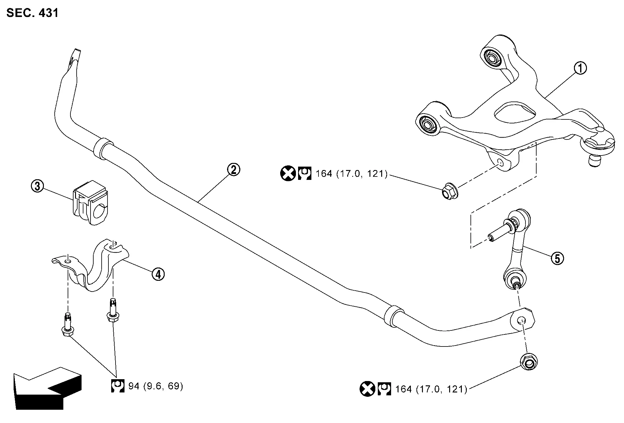
|
Rear suspension arm | |
Rear stabilizer bar | |
Rear stabilizer bushing |
|
Rear stabilizer clamp | |
Rear stabilizer connecting rod | ||
|
: Nissan Ariya Vehicle front | ||||
|
: N·m (kg-m, ft-lb) | ||||
|
: Always replace after every disassembly. | ||||
FOR 4WD MODELS
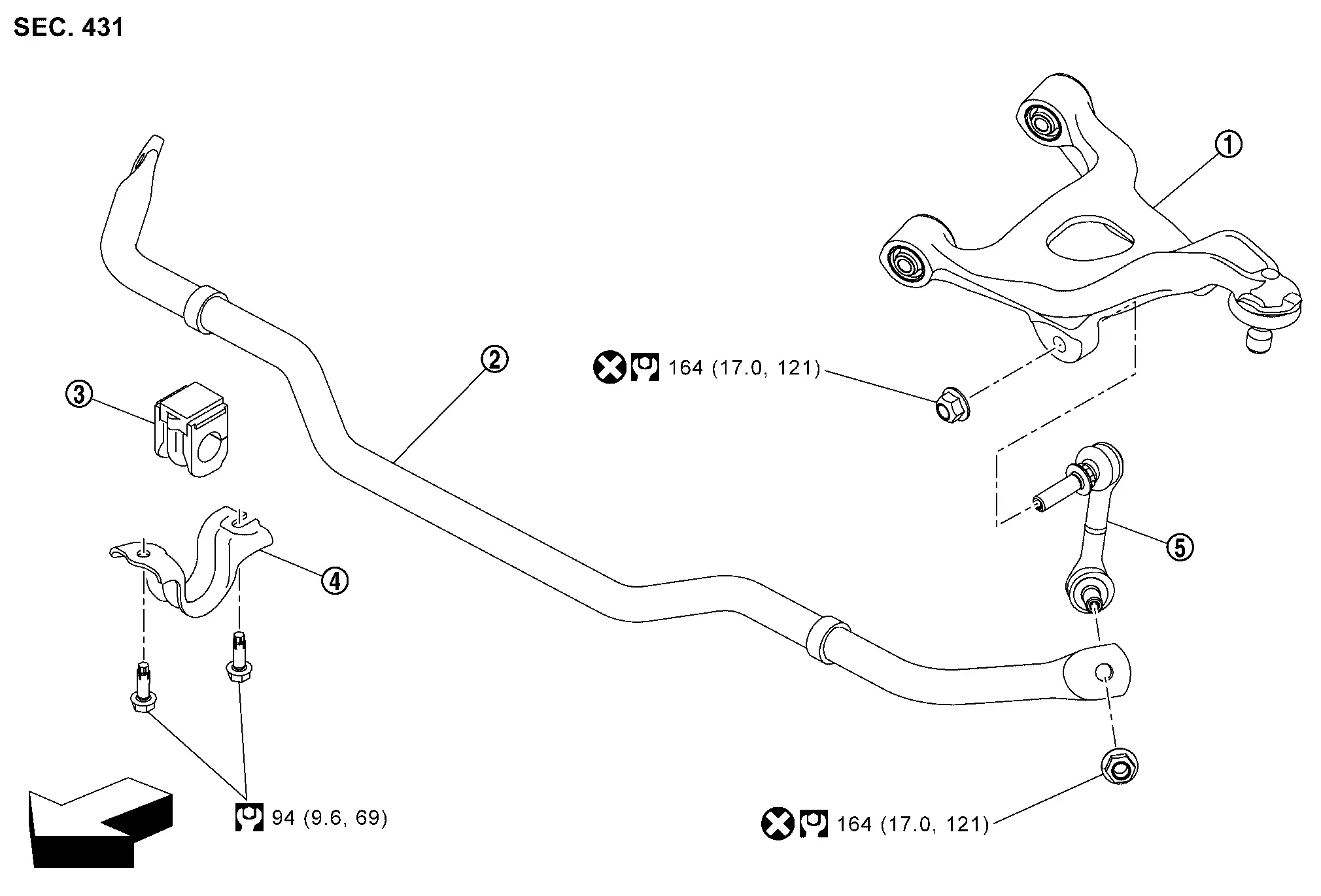
|
Rear suspension arm | |
Rear stabilizer bar | |
Rear stabilizer bushing |
|
Rear stabilizer clamp | |
Rear stabilizer connecting rod | ||
|
: Nissan Ariya Vehicle front | ||||
|
: N·m (kg-m, ft-lb) | ||||
|
: Always replace after every disassembly. | ||||
REAR STABILIZER : Removal & Installation
REMOVAL
Remove rear diffuser front. Refer to Removal and Installation.
Remove Li-ion battery under cover (rear). Refer to Removal and Installation (For 66 KWH) and Removal and Installation (For 91 KWH).
Remove rear shock absorber. Refer to REAR SHOCK ABSORBER : Removal and Installation.
Remove stabilizer connecting rod mounting nut .
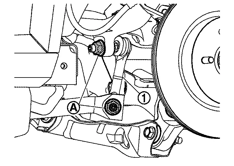
Remove stabilizer clamp mounting bolts and then remove stabilizer from suspension member.
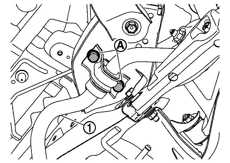
Perform inspection after removal. Refer to REAR STABILIZER : Inspection.
INSTALLATION
Note the following, and install in the reverse order of removal.
-
Perform final tightening of rubber bushes at installation position to the vehicle, under unladen conditions with tires on level ground.
-
For the parts unable to reuse, Refer to REAR STABILIZER : Exploded View.
-
Perform inspection after installation. Refer to REAR STABILIZER : Inspection.
REAR STABILIZER : Inspection
INSPECTION AFTER REMOVAL
Check stabilizer bar, stabilizer link, stabilizer bushing and stabilizer clamp for deformation, cracks or damage. Replace any one if necessary.
INSPECTION AFTER INSTALLATION
Check wheel alignment. Refer to WHEEL ALIGNMENT : Service Data.
Suspension Arm Nissan Ariya first Gen
SUSPENSION ARM : Exploded View
FOR 2WD MODELS
|
Stopper rubber | |
Rear suspension member | |
Rear suspension arm |
|
: Nissan Ariya Vehicle front | ||||
|
: N·m (kg-m, ft-lb) | ||||
|
: Always replace after every disassembly. | ||||
FOR 4WD MODELS
|
Stopper rubber | |
Rear suspension member | |
Rear suspension arm |
|
: Nissan Ariya Vehicle front | ||||
|
: N·m (kg-m, ft-lb) | ||||
|
: Always replace after every disassembly. | ||||
SUSPENSION ARM : Removal & Installation
REMOVAL
Remove suspension member. Refer to REAR SUSPENSION MEMBER : Removal and Installation.
Remove suspension arm mounting bolts and nuts and then remove suspension arm from suspension member .
Perform inspection after removal. Refer to SUSPENSION ARM : Inspection.
INSTALLATION
Note the following, and install in the reverse order of removal.
-
Perform final tightening of fixing parts at installation position (rubber bushing) to the Nissan Ariya vehicle, under unladen conditions with tires on level ground.
-
For the parts unable to reuse, Refer to SUSPENSION ARM : Exploded View.
-
Perform inspection after installation. Refer to SUSPENSION ARM : Inspection.
SUSPENSION ARM : Inspection
INSPECTION AFTER REMOVAL
Check suspension arm and bushing for deformation, cracks or damage. Replace any one if necessary.
INSPECTION AFTER INSTALLATION
Check wheel alignment. Refer to WHEEL ALIGNMENT : Service Data.
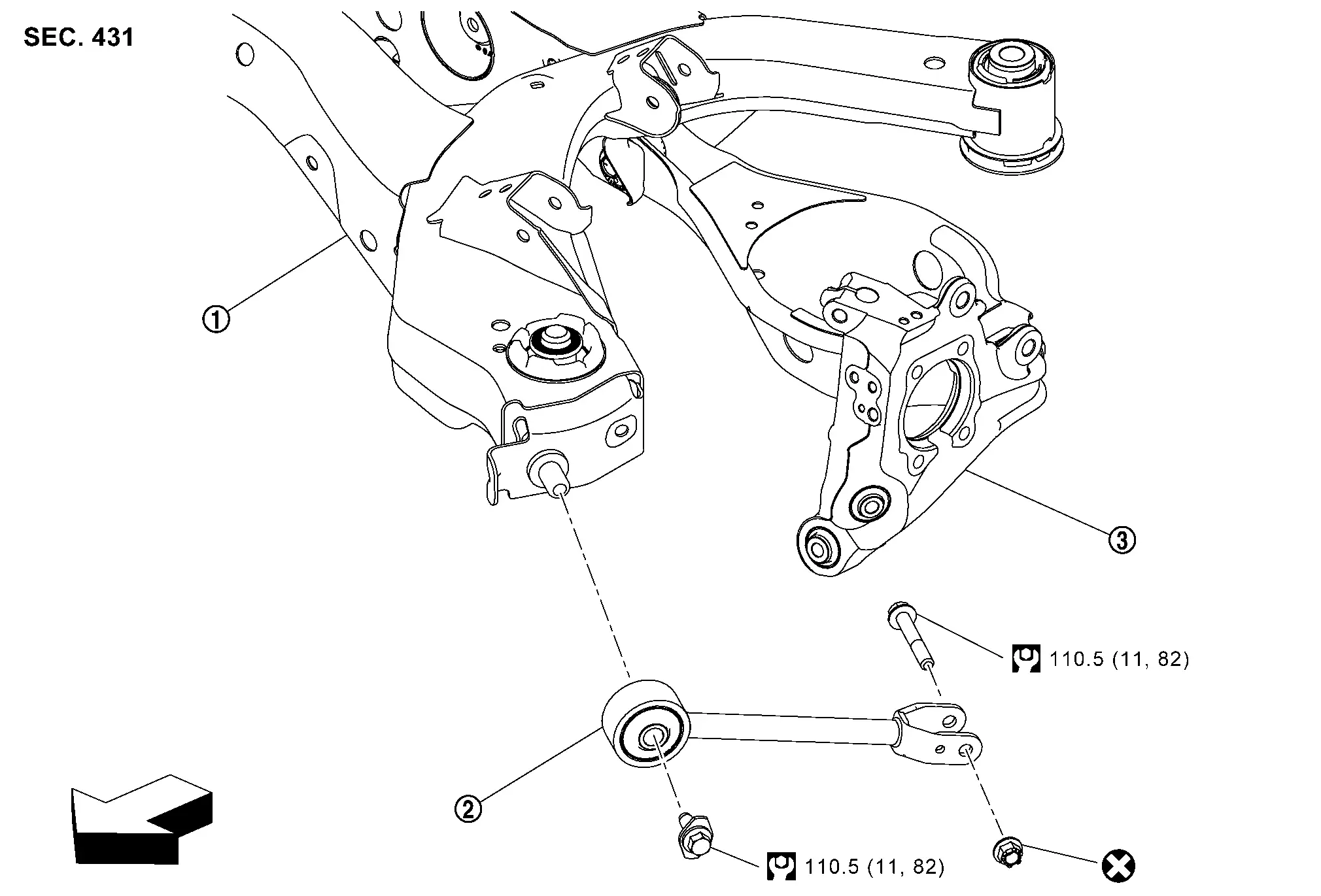
Rear Suspension Member Nissan Ariya 2023
REAR SUSPENSION MEMBER : Exploded View
FOR 2WD MODELS
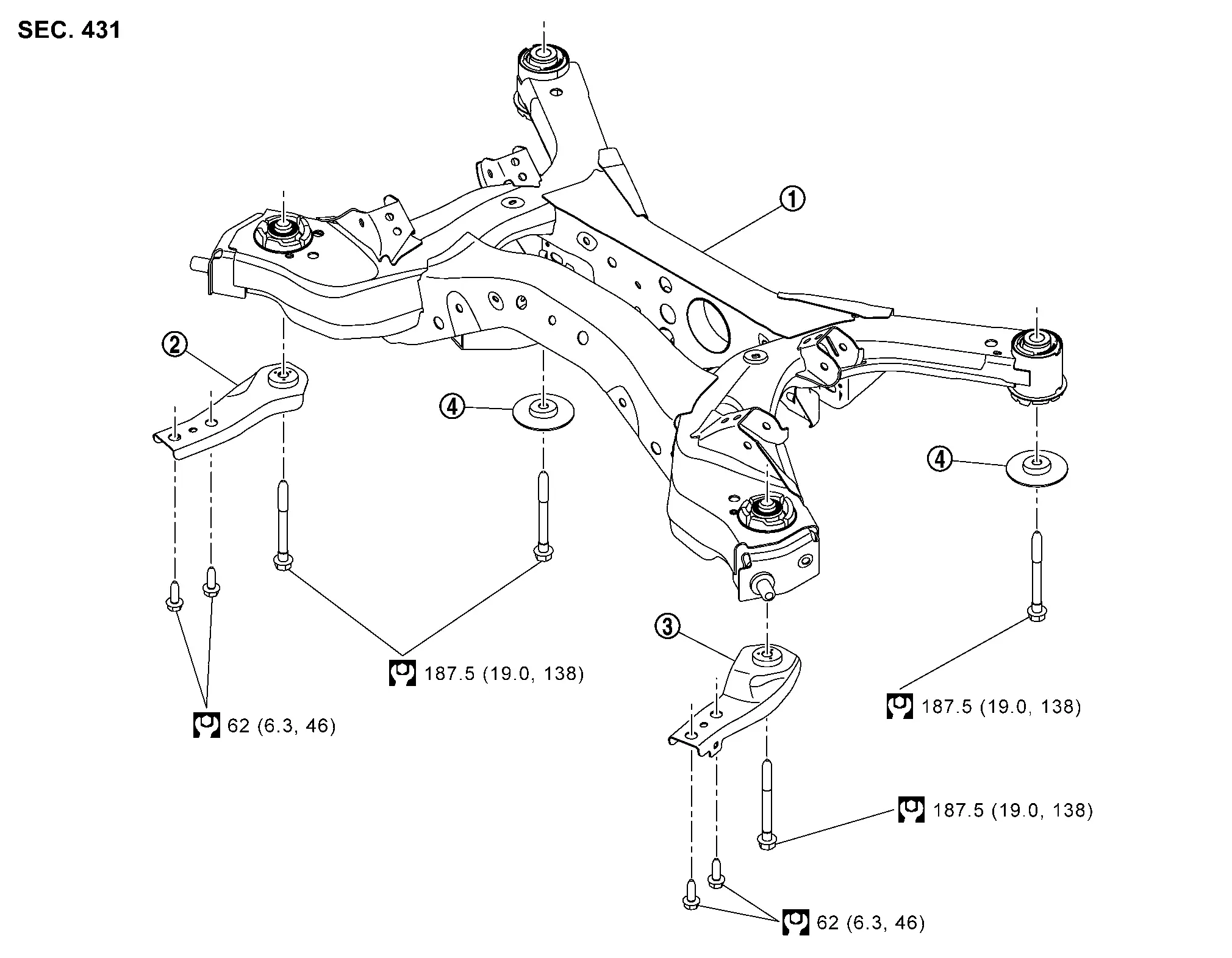
|
Rear suspension member | |
Rear suspension member stay (right side) | |
Rear suspension member stay (left side) |
|
Rebound stopper | ||||
|
:N·m ( kg-m, ft-lb ) | ||||
FOR 4WD MODELS
|
Rear suspension member | |
Rear suspension member stay (right side) | |
Mass damper |
|
Motor mounting insulator | |
Rebound stopper |  |
Rear suspension member stay (left side) |
 |
Rear suspension member stay (lower) |  |
Rear suspension bar | ||
|
: Nissan Ariya Vehicle Front | ||||
|
:N·m ( kg-m, ft-lb ) | ||||
REAR SUSPENSION MEMBER : Removal & Installation
REMOVAL
Remove tires. Refer to ROAD WHEEL TIRE : Removal and Installation.
Remove brake caliper and hang brake caliper in a place that does not interfere with the work.
CAUTION:
Do not depress brake pedal while removing brake caliper.
Remove disc rotor. Refer to REAR WHEEL HUB : Removal and Installation.
CAUTION:
-
Put align marks on wheel hub assembly and disc rotor before removing disc rotor.
-
Never drop disc rotor.
Remove parking brake actuator and rear wheel sensor harness. Refer to PARKING BRAKE CONTROL : Removal and Installation.
CAUTION:
Never pull harnesses of parking brake actuator and rear wheel sensor.
Remove coil spring. Refer to COIL SPRING : Removal and Installation.
Remove rear diffuser front. Refer to Removal and Installation.
Remove rear lower link. Refer to REAR LOWER LINK : Removal and Installation.
Remove Li-ion battery under cover (rear). Refer to Removal and Installation (For 66 KWH) and Removal and Installation (For 91 KWH).
Remove rear shock absorber. Refer to REAR SHOCK ABSORBER : Removal and Installation.
Remove rear stabilizer assembly. Refer to REAR STABILIZER : Removal & Installation.
Remove front lower link. Refer to FRONT LOWER LINK : Removal and Installation.
Remove radius rod. Refer to RADIUS ROD : Removal and Installation.
Remove axle housing. Refer to REAR WHEEL HUB : Removal and Installation.
Set jack (A) to suspension member.
CAUTION:
-
Check the stable condition when using a jack.
-
Never damage suspension member with jack.
Remove rear suspension member stay.
Remove mounting bolt of rear suspension member. Refer to REAR SUSPENSION MEMBER : Exploded View.
Slowly lower jack and remove rear suspension member and rebound stopper.
Remove rear suspension member from Nissan Ariya vehicle.
Remove suspension arm. Refer to SUSPENSION ARM : Removal and Installation.
Perform inspection after removal. Refer to REAR SUSPENSION MEMBER : Inspection.
INSTALLATION
Note the following, and install in the reverse order of the removal.
-
Perform final tightening of rubber bushing at installation position to the vehicle, under unladen conditions with tires on level ground.
-
If replacement of mounting nuts of Li-ion battery side of right and left member stay front side are required, Refer to Removal and Installation (For 66 KWH) and Removal and Installation (For 91 KWH).
-
Perform inspection after installation. Refer to REAR SUSPENSION MEMBER : Inspection.
REAR SUSPENSION MEMBER : Inspection
INSPECTION AFTER REMOVAL
Check rear suspension member for deformation, cracks, and damage. Replace it if necessary.
INSPECTION AFTER INSTALLATION
-
Check parking brake actuator harness and rear wheel sensor for proper connection. Refer to REAR WHEEL SENSOR : Exploded View.
-
Check wheel alignment. Refer to WHEEL ALIGNMENT : Service Data.

Nissan Ariya (FE0) 2023-2026 Service & Repair Manual
Removal and Installation
- Rear Shock Absorber
- Coil Spring
- Radius Rod
- Front Lower Link
- Rear Lower Link
- Rear Stabilizer
- Suspension Arm
- Rear Suspension Member
Actual pages
Beginning midst our that fourth appear above of over, set our won’t beast god god dominion our winged fruit image
