Nissan Ariya: Removal and Installation
Reduction Gear Differential Side Oil Seal Nissan Ariya
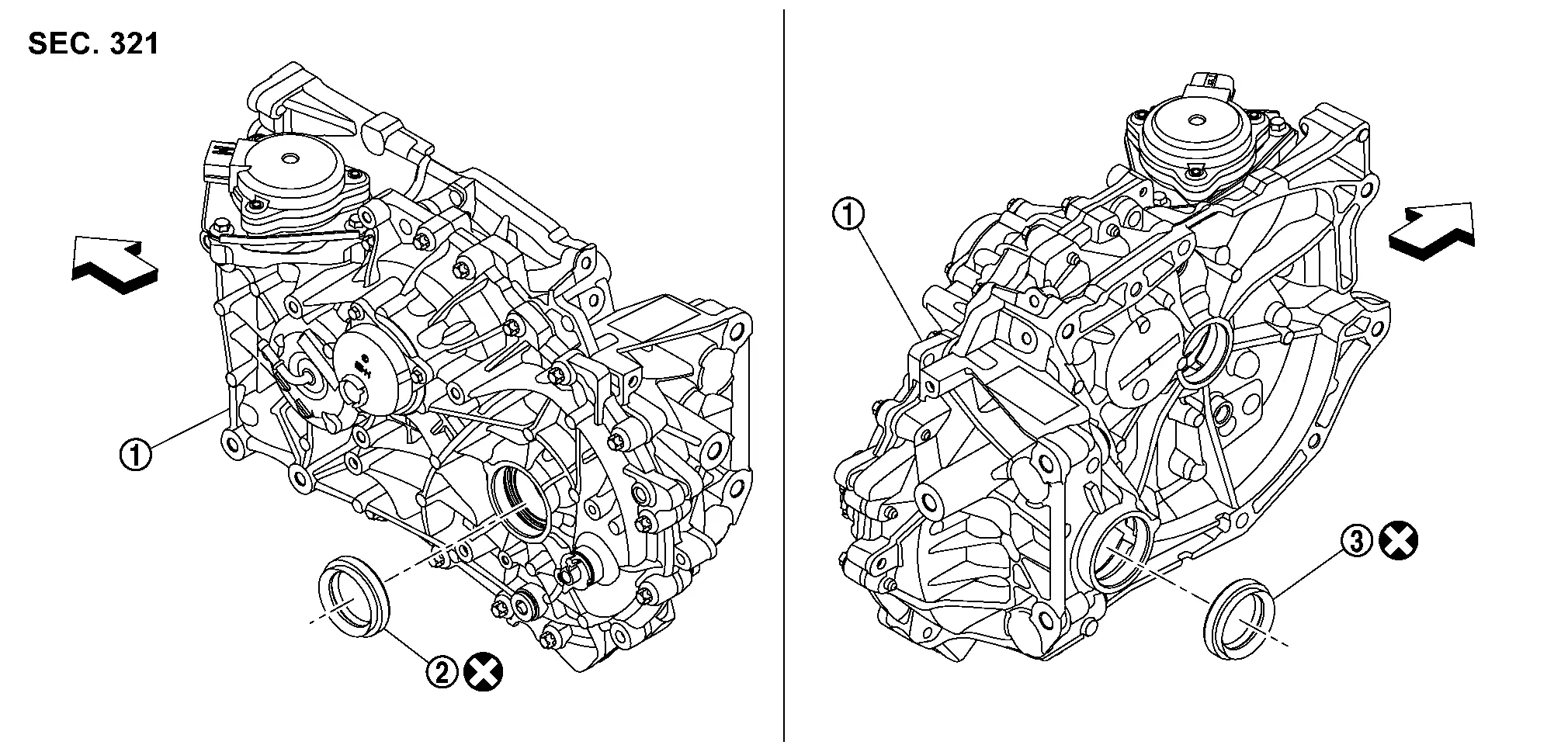
REDUCTION GEAR DIFFERENTIAL SIDE OIL SEAL : Exploded View
 |
Reduction gear |  |
Side oil seal (left side) |  |
Side oil seal (right side) |
 : Nissan Ariya Vehicle front : Nissan Ariya Vehicle front |
|||||
 : Always replace after every disassembly. : Always replace after every disassembly. |
|||||
REDUCTION GEAR DIFFERENTIAL SIDE OIL SEAL : Removal & Installation
REMOVAL
Remove the front drive shaft (LH side and/or RH side). Refer to FRONT DRIVE SHAFT: Removal & Installation.
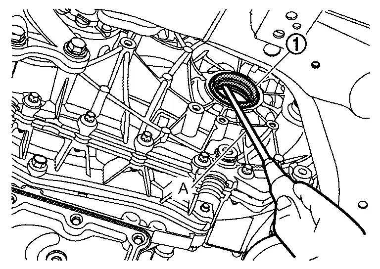
Remove side oil seal (left side and/or right side), using oil seal remover (A) (commercial service tool).
CAUTION:
Never damage mounting surfaces of the side oil seal.
INSTALLATION
Note the following, and install in the reverse order of removal.
-
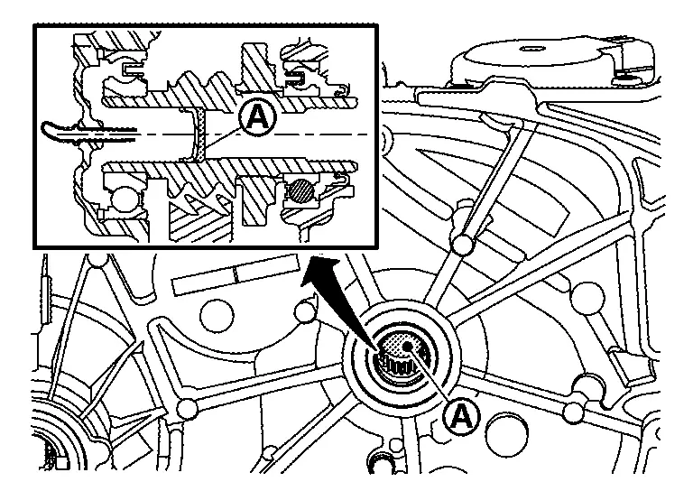
Using a drift (commercial service tools), drive the side oil seal
within the dimension (C) and (D) shown as follows.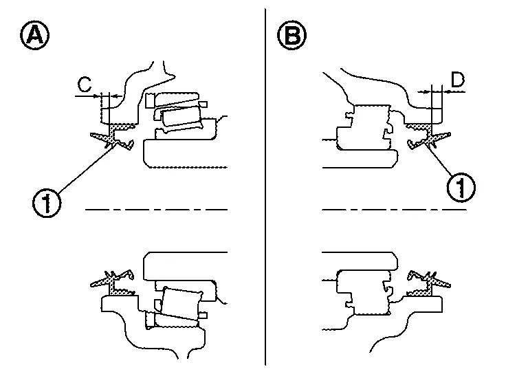

: Left side 
: Right side Dimension (C) : 2.6 ±0.3 mm (0.102 ±0.012 in) Dimension (D) : 3.45 ±0.3 mm (0.1358 ±0.012 in) CAUTION:
-
Never reuse oil seal.
-
Be careful not to scratch the lip of the oil seal.
-
When installing, never incline oil seal.
-
If oil seal is inserted deeper than the reference value, use new oil seal and perform installing again.
 NOTE:
NOTE:
The reference is the pull-in direction of the side oil seal.
-
-
Check the oil level and the oil leakage after installation. And check the oil leakage from reduction gear again, after driving the Nissan Ariya vehicle. Refer to REDUCTION GEAR OIL : Inspection.
Reduction Gear Air Breather Nissan Ariya first Gen
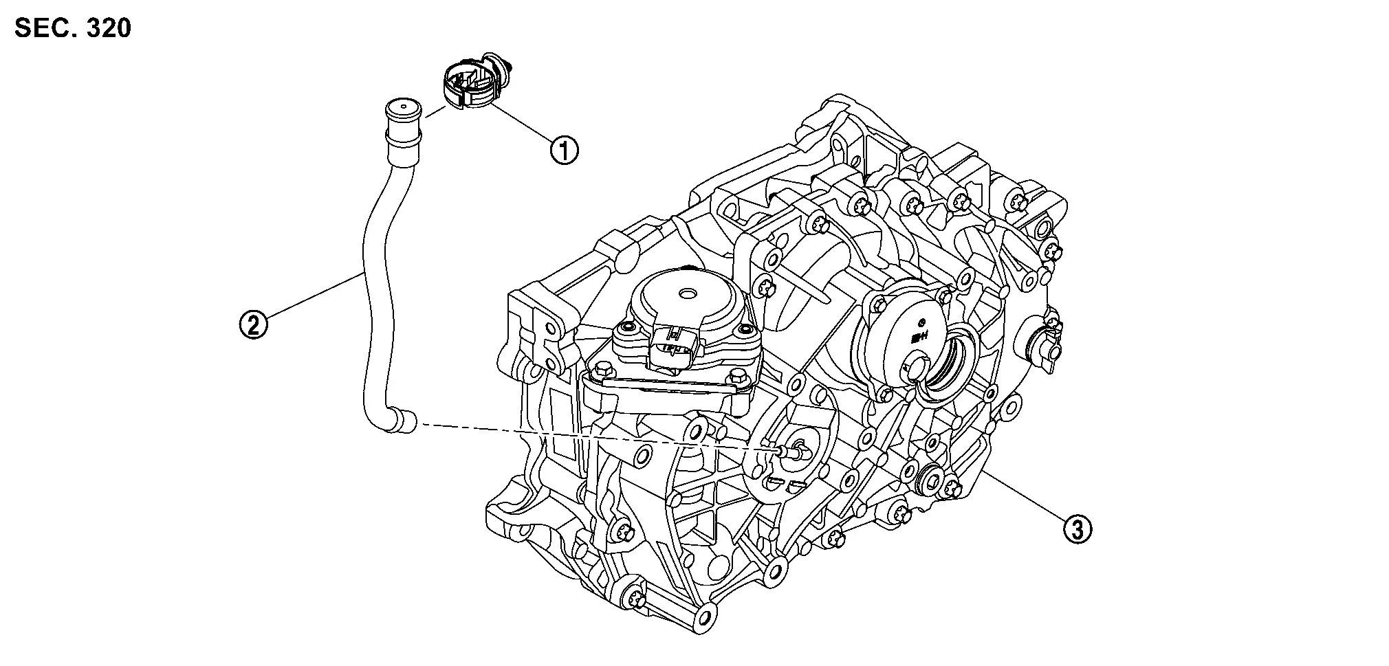
REDUCTION GEAR AIR BREATHER : Exploded View
|
Clip | |
Air breather hose | |
Reduction gear |
REDUCTION GEAR AIR BREATHER : Removal & Installation
REMOVAL
Remove high voltage power delivery assembly. Refer to HIGH VOLTAGE POWER DELIVERY ASSEMBLY : Removal & Installation.
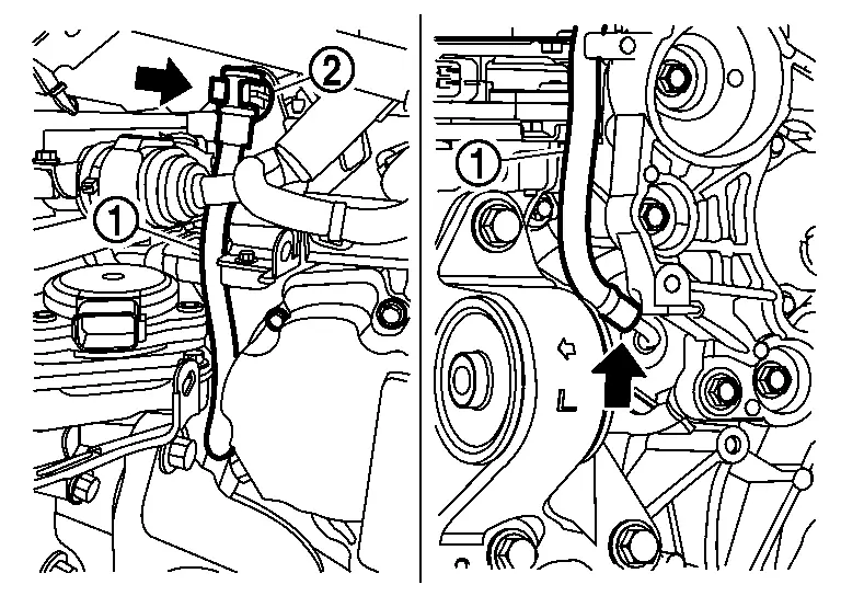
Remove air breather hose and clip .
INSTALLATION
Note the following, and install in the reverse order of removal.
-
When installing air breather hose, preventing crush and clogging caused by bending.
-
Insert the air breather hose all the way to the bulged part of tube.
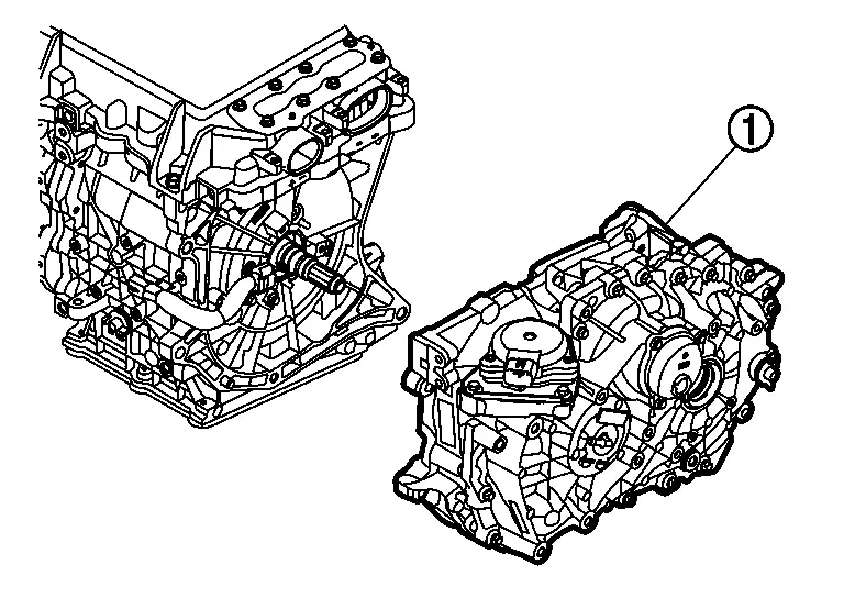
Reduction Gear Nissan Ariya 2023
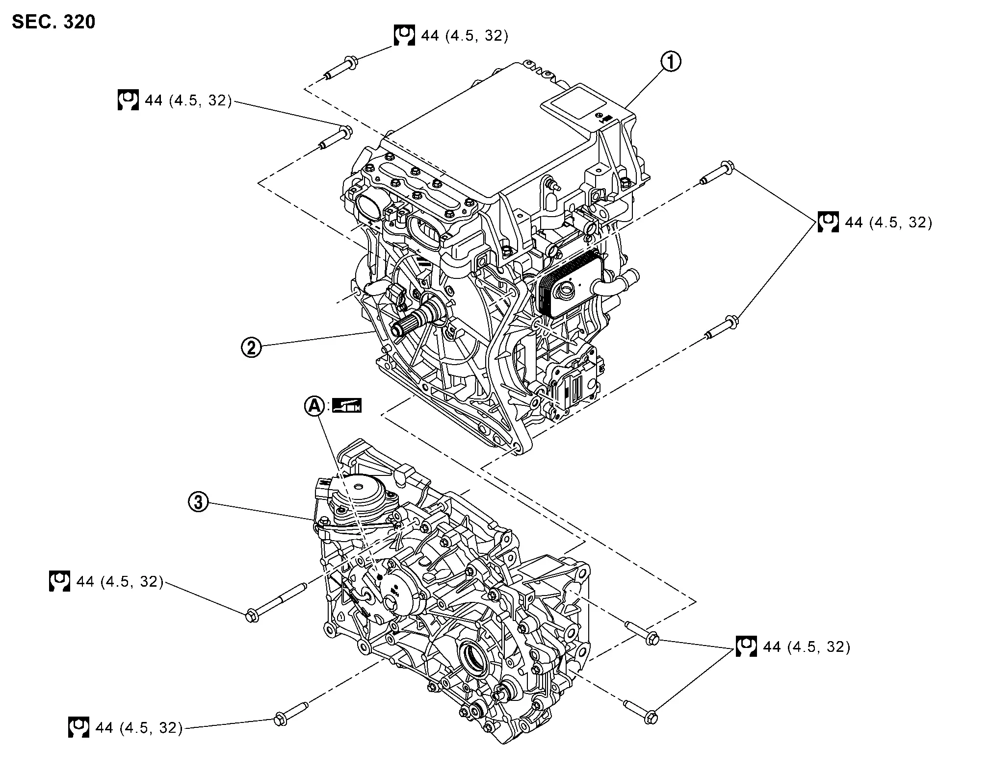
REDUCTION GEAR : Exploded View
|
Inverter (front) | |
Front traction motor | |
Reduction gear |
|
Inside of input shaft (insertion part of front traction motor shaft splines) | ||||
 : N·m (kg-m, ft-lb) : N·m (kg-m, ft-lb) |
|||||
 : Apply lithium-based grease including molybdenum disulphide. : Apply lithium-based grease including molybdenum disulphide. |
|||||
REDUCTION GEAR : Unit Removal & Installation
REMOVAL
Drain the gear oil. Refer to REDUCTION GEAR OIL : Draining.
Remove front suspension member assembly, together with reduction gear and front traction motor with inverter (front) from Nissan Ariya vehicle. Refer to FRONT SUSPENSION MEMBER : Removal & Installation.
Remove reduction gear, front traction motor and inverter (front) as a set from front suspension member assembly. Refer to FRONT TRACTION MOTOR : Removal & Installation.
Remove reduction gear air breather hose. Refer to REDUCTION GEAR AIR BREATHER : Removal & Installation.
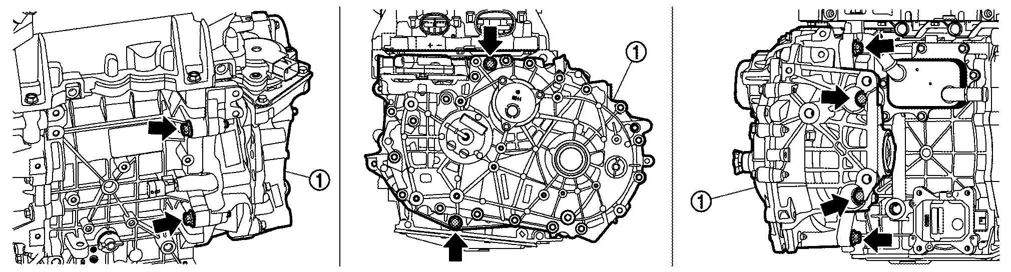
Remove compressor bracket , motor mounting LH bracket , and motor mounting rear bracket .
-
Compressor bracket: Refer to Removal & Installation.
-
Motor mounting LH bracket and motor mounting rear bracket: Refer to FRONT TRACTION MOTOR : Removal & Installation.
Remove the bolts that fasten reduction gear and front traction motor.
Remove reduction gear from front traction motor.
INSTALLATION
Note the following, and install in the reverse order of removal.
-
For each tightening torque, Refer to REDUCTION GEAR : Exploded View.
-
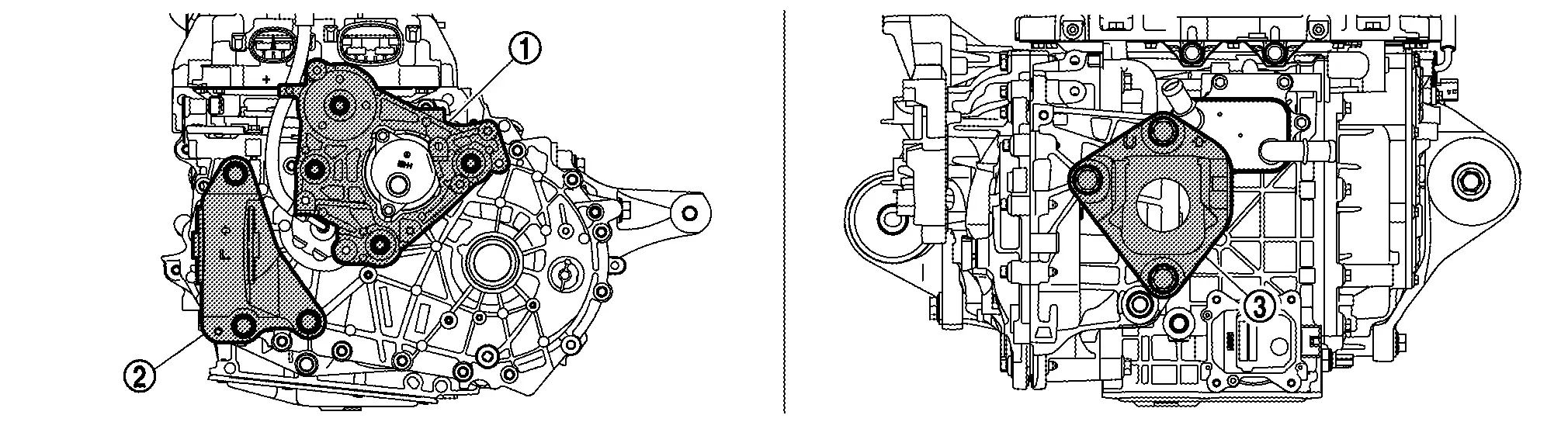
Check fitting of dowel pins
on front traction motor side of reduction gear installation surface, and remove any moisture, oil, or foreign material from matching surface on front traction motor and reduction gear.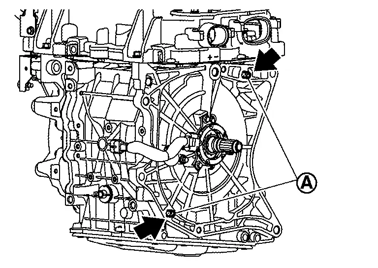
-
Before installing reduction gear to front traction motor, apply recommended grease to the inside of reduction gear input shaft (insertion part of front traction motor shaft splines), as per the following procedure.
-
For applying grease, Refer to REDUCTION GEAR : Exploded View.
-
-
Clean front traction motor shaft splines and inside of reduction gear input shaft to remove old grease and powder arisen from abrasion.
-
Inject the specified amount of recommended grease into the reduction gear input shaft back side (greasing part:
).
Specified grease amount : 3.5 ±0.5 g (0.12 ±0.018 oz) CAUTION:
Be sure not to exceed specified amount of grease. Excessive grease may overflow during installing and break the O-ring.
-
When removing reduction gear from front traction motor, replace O-ring of front traction motor shaft. Refer to FRONT TRACTION MOTOR : Exploded View.
-
When installing reduction gear
to front traction motor , align markings on reduction gear input shaft and front traction motor shaft.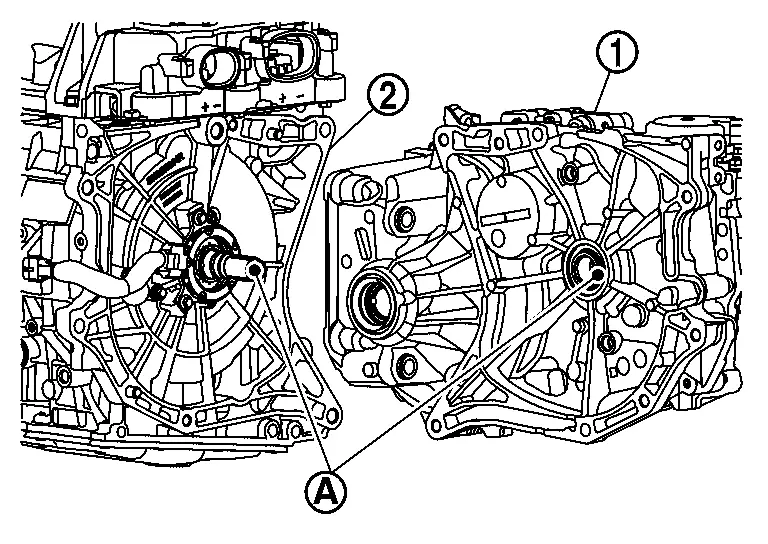 NOTE:
NOTE:
The marking
on front traction motor shaft is shown in the figure.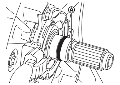
-
Check the oil level and the oil leakage after installation. Refer to REDUCTION GEAR OIL : Inspection.
-
When replacing reduction gear, perform adjustment after installation.Refer to REDUCTION GEAR : Adjustment.
REDUCTION GEAR : Adjustment
ADJUSTMENT AFTER INSTALLATION
When replaced reduction gear assembly, perform P position learning of parking actuator. Refer to Work Procedure.

Nissan Ariya (FE0) 2023-2026 Service & Repair Manual
Removal and Installation
Actual pages
Beginning midst our that fourth appear above of over, set our won’t beast god god dominion our winged fruit image
