Nissan Ariya: Removal and Installation
Rear Wheel Hub and Housing Nissan Ariya 2026
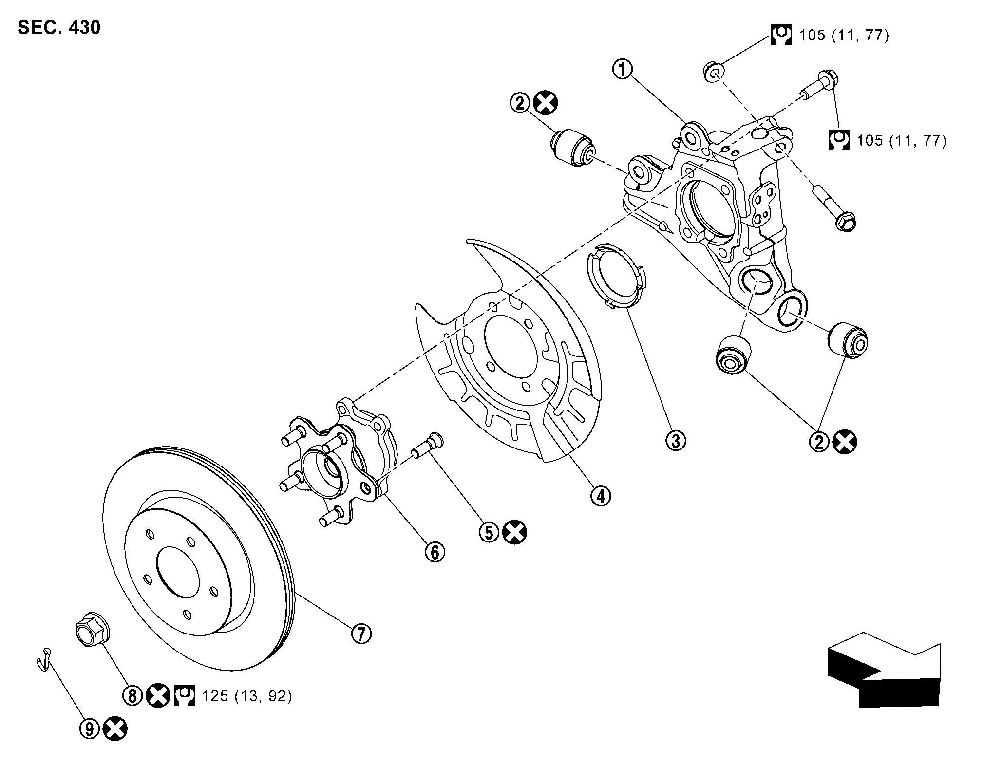
Exploded View
 |
Axle housing |  |
Bushing |  |
Hub cap |
 |
Back plate |  |
Hub bolt |  |
Wheel hub and bearing assembly |
 |
Disc rotor |  |
Wheel hub lock nut |  |
Cotter pin |
 |
: Nissan Ariya Vehicle front | ||||
 |
: N·m (kg-m, ft-lb) | ||||
 |
: Always replace after every disassembly. | ||||
Removal and Installation
REMOVAL
Remove tires. Refer to Exploded View.
Remove wheel sensor from axle housing. Refer to Removal & Installation.
Remove caliper assembly. Hang caliper assembly in a place where it will not interfere with work. Refer to Exploded View.
CAUTION:
Never depress brake pedal while brake caliper is removed.
Remove disc rotor.
CAUTION:
-
Put matching marks
 on the wheel hub and bearing assembly and the disc rotor before removing the disc rotor.
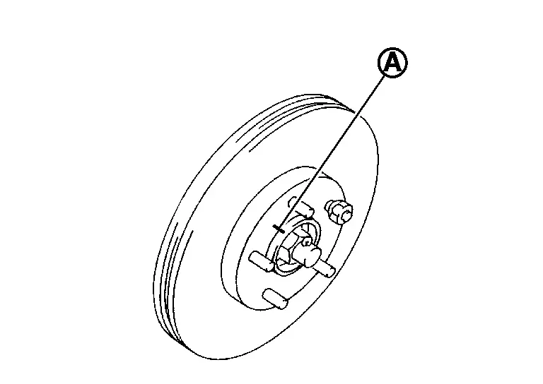
-
Never drop disc rotor.
Remove wheel hub lock nut. Refer to Exploded View.
Remove wheel hub and bearing assembly mounting bolts .
Remove wheel hub and bearing assembly and back plate.
Remove radius rod. Refer to Removal & Installation.
Remove front lower link. Refer to Removal & Installation.
Remove coil spring. Refer to Removal & Installation.
Remove rear suspension arm mounting bolts and nuts  from axle housing .
Separate rear suspension arm, and then remove axle housing.
Remove hub bolts from wheel hub and bearing assembly, using the ball joint remover (A) (commercial service tool).
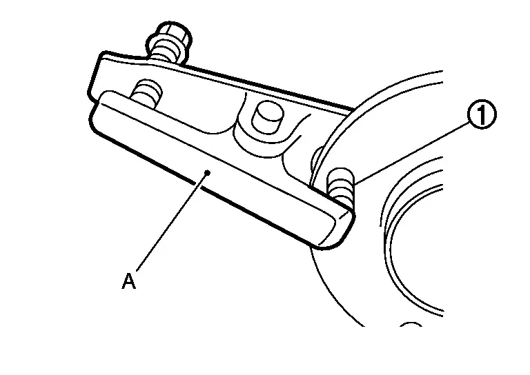
CAUTION:
-
Remove hub bolt only when necessary.
-
Never hammer the hub bolt to avoid impact to the wheel hub and bearing assembly.
-
Pull out the hub bolt in a direction perpendicular to the wheel hub and bearing assembly.
Perform inspection after removal. Refer to Inspection.
INSTALLATION
Note the following, and install in the reverse order of removal.
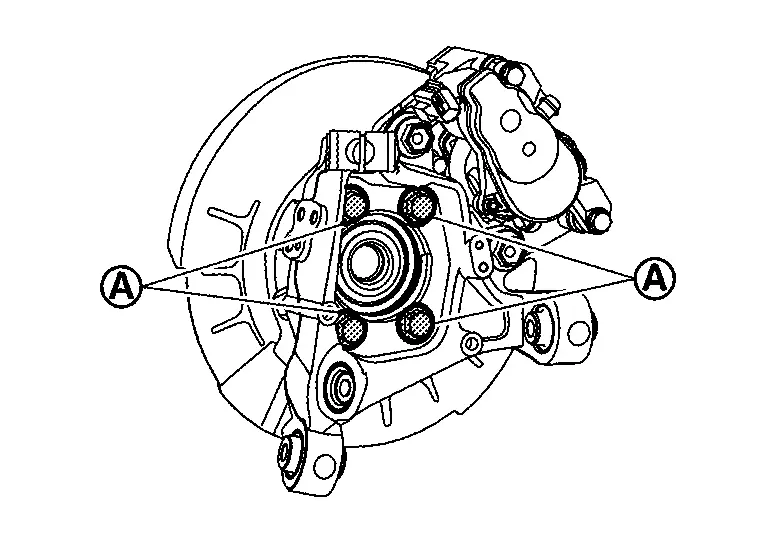
-
Place a washer
as shown in the figure to install the hub bolts by using the tightening force of the nut .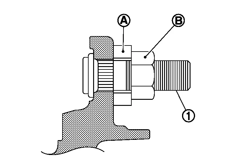
CAUTION:
-
Check that there is no clearance between wheel hub and bearing assembly, and hub bolt.
-
Never reuse hub bolt.
-
-
Align the matching marks
made during removal when reusing the disc rotor.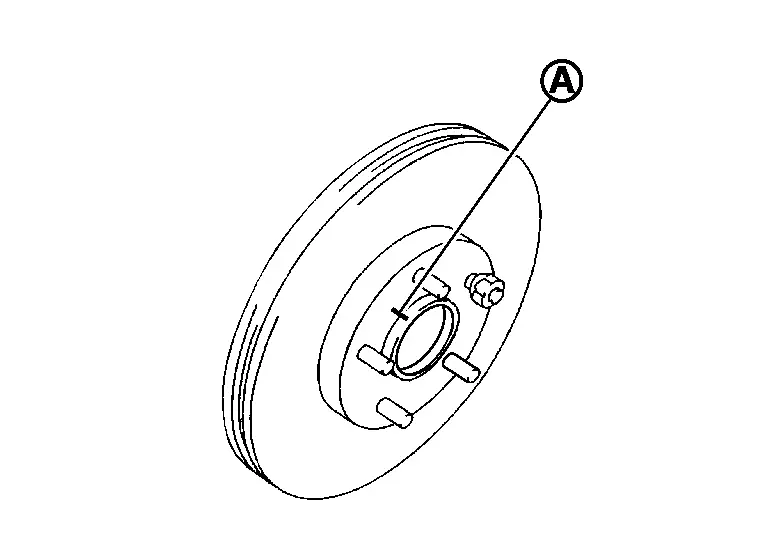
-
Perform inspection after installation. Refer to Inspection.
Inspection
INSPECTION AFTER REMOVAL
Check wheel hub and bearing assembly for wear, cracks, and damage. Replace if there are.
INSPECTION AFTER INSTALLATION
Check wheel sensor harness for proper connection. Refer to Exploded View.
If pressing the piston of rear brake caliper assembly, perform "REMOVAL/REPLACEMENT OF REAR BRAKE PAD OR REAR BRAKE CALIPER". Refer to Removal & Installation.
Check wheel alignment. Refer to Inspection.
Adjust neutral position of steering angle sensor. Refer to Work Procedure.
Rear Drive Shaft Nissan Ariya: FE0
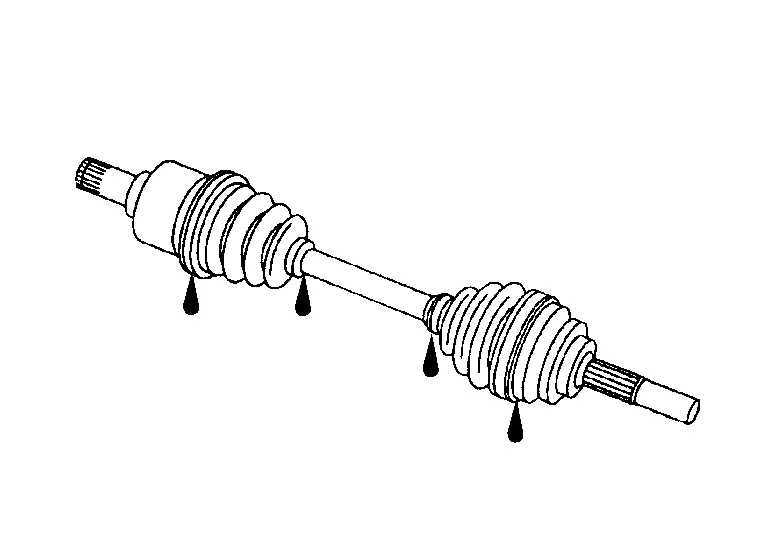
Exploded View
FOR RH DRIVE SHAFT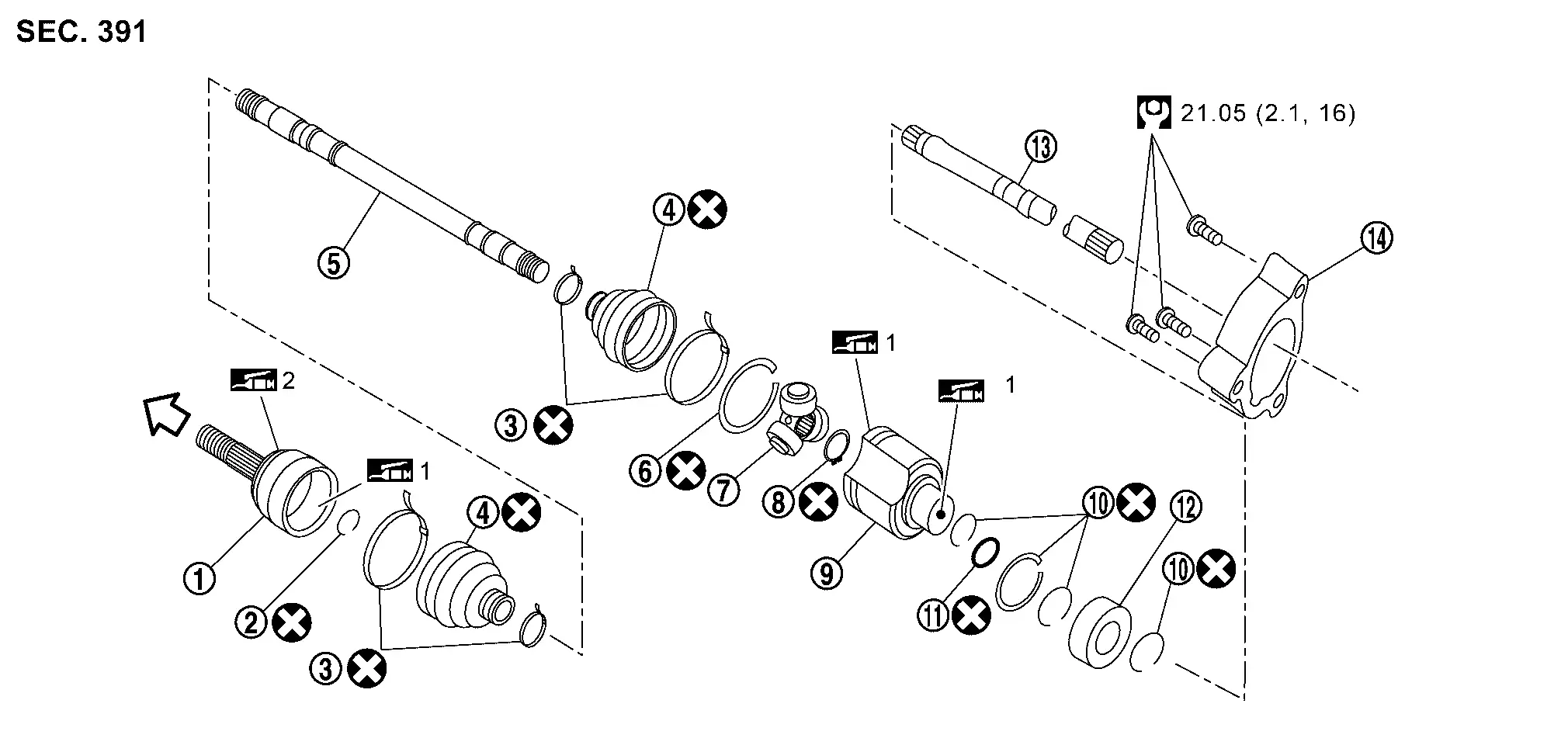
|
Joint sub-assembly | |
Circular clip | |
Boot band |
|
Boot | |
Shaft | |
Stopper ring |
|
Spider assembly | |
Snap ring | |
Housing |
 |
Circular clip |  |
O-ring |  |
Bearing |
 |
Link SFT |  |
Bearing bracket | ||
|
: Wheel side | ||||
|
: N·m (kg-m, ft-lb) | ||||
 1 1 |
: Nissan genuine designated grease (Refer to parts catalog) | ||||
| 2 |
: Apply paste [service parts (440037S000)] | ||||
|
: Always replace after every disassembly. | ||||
FOR LH DRIVE SHAFT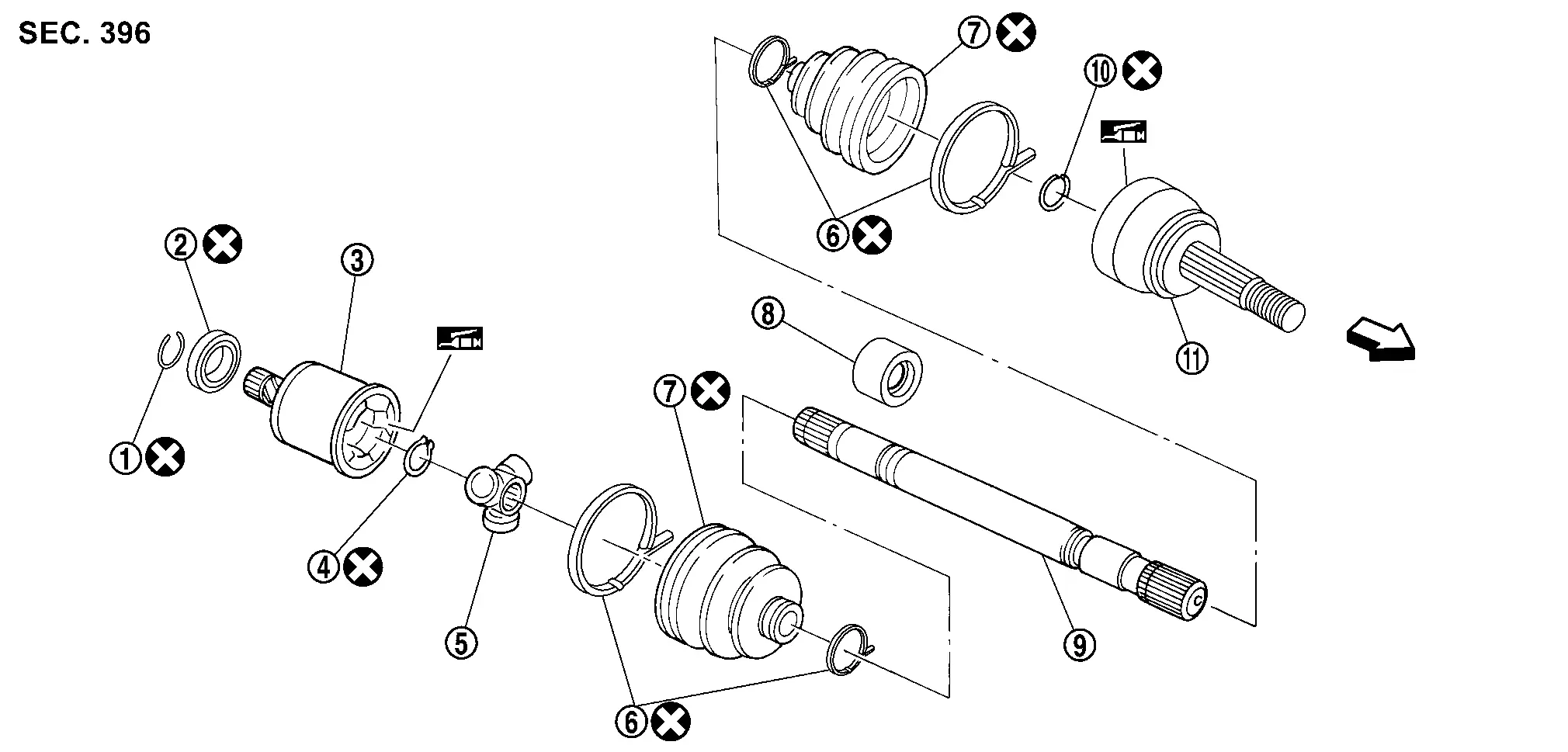
|
Circular clip | |
Dust shield | |
Housing |
|
Snap ring | |
Spider assembly | |
Stopper ring |
|
Boot band | |
Boot | |
Shaft |
|
Circular clip | |
Joint sub-assembly | ||
|
: Wheel side | ||||
|
: Fill NISSAN genuine grease or an equivalent. | ||||
|
: Always replace after every disassembly. | ||||
Removal and Installation
REMOVAL
Remove tires. Refer to Removal & Installation.
Remove wheel sensor from wheel hub and bearing assembly. Refer to Removal & Installation.
Remove caliper assembly. Hang caliper assembly in a place where it will not interfere with work. Refer to Removal & Installation.
CAUTION:
Never depress brake pedal while brake caliper is removed.
Remove disc rotor. If disc rotor cannot be removed, remove as follows.
CAUTION:
-
Parking brake completely in the released position.
-
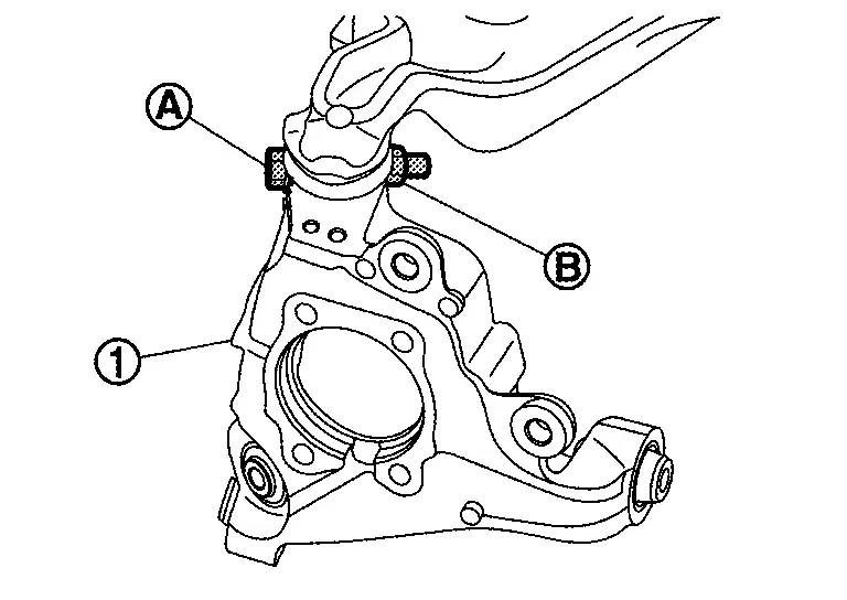
Put matching marks
on the wheel hub and bearing assembly and the disc rotor before removing the disc rotor. -
Never drop disc rotor.
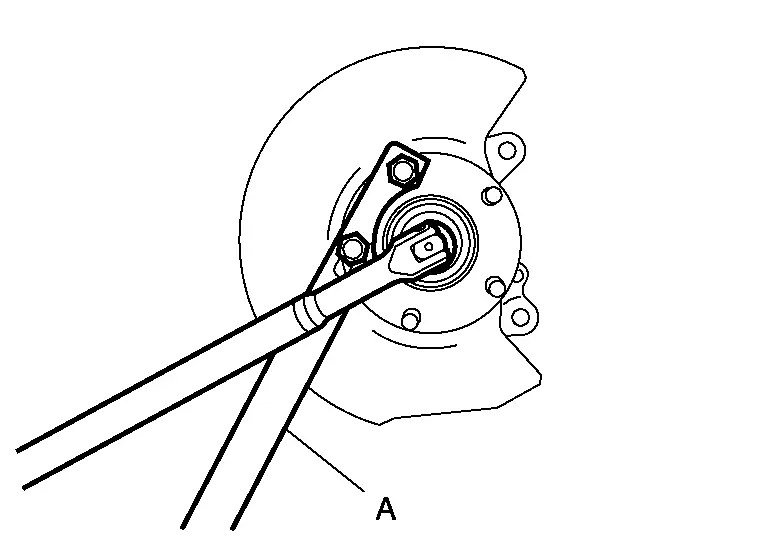
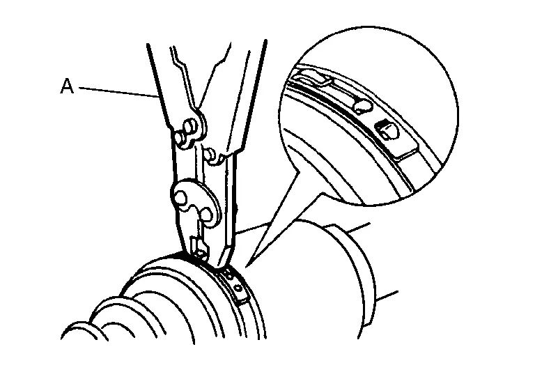
Remove cotter pin, and then loosen wheel hub lock nut, using a wheel hub lock nut wrench (A) (SST: KV40104000).
Patch hub lock nut with a piece of wood. Hammer the wood to disengage wheel hub and bearing assembly from drive shaft.
 NOTE:
NOTE:
Use suitable puller, if wheel hub and bearing assembly and drive shaft cannot be separated even after performing the above procedure.
Remove wheel hub and bearing assembly.
CAUTION:
Remove parking brake assembly only when necessary.
Remove back plate.
Remove hub cap.
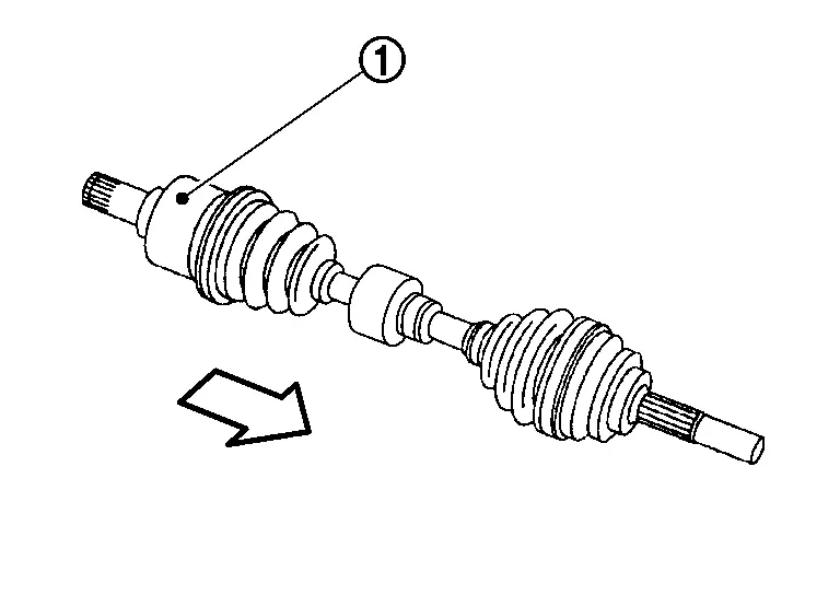
Remove the rear drive shaft from transaxle assembly.
CAUTION:
-
Never place drive shaft joint at an extreme angle.
-
Be careful not to overextend slide joint.
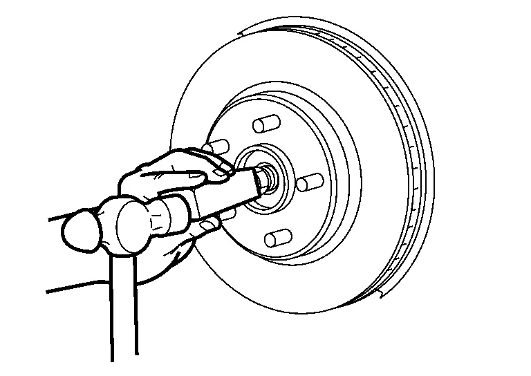
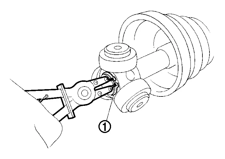
Remove the rear drive shaft from the rear final drive.
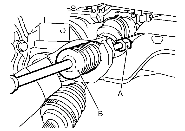
-
Use the drive shaft attachment (A) (SST: KV40107500) and a sliding hammer (B) while inserting tip of the drive shaft attachment between housing and final drive assembly.
CAUTION:
-
Never place drive shaft joint at an extreme angle when removing drive shaft. Also be careful not to overextend slide joint.
-
Confirm that the circular clip is attached to the drive shaft.
-
Perform inspection after removal. Refer to Inspection.
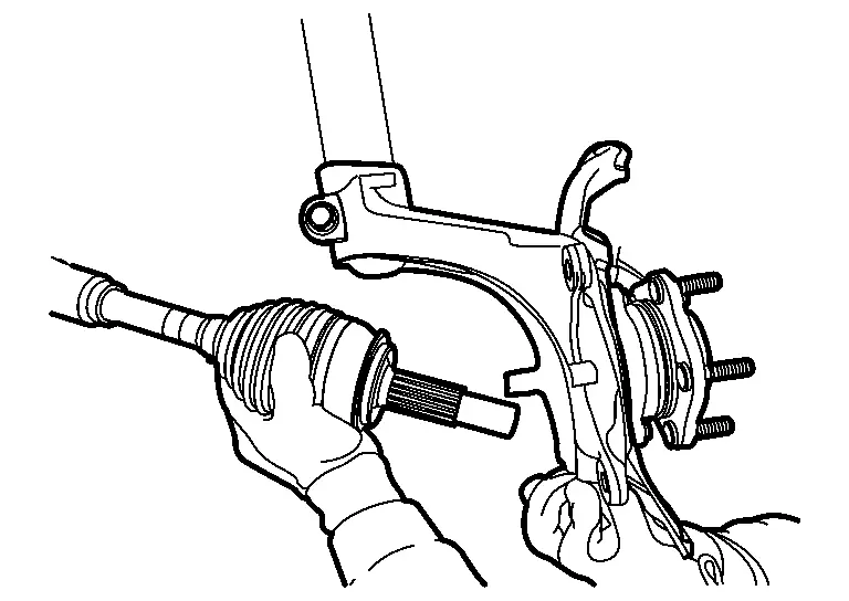
INSTALLATION
Note the following, and install in the reverse order of removal.
CAUTION:
Always replace side oil seal with new one when installing drive shaft. Refer to REDUCTION GEAR DIFFERENTIAL SIDE OIL SEAL : Removal & Installation.
RH SIDE
-
Install New O-ring to link shaft.
CAUTION:
-
Apply grease (MOLYKOTE BR2 plas correspnding) to all length and aroud
of the spline.Amount paste 0.5– 1.2 g (0.04 – 0.10 oz)
-
Insert drive shaft and slide the slide joint of drive shaft like a hammering to securely install it.
CAUTION:
-
Upon set insertion, O-ring must not be damaged.
WARNING:
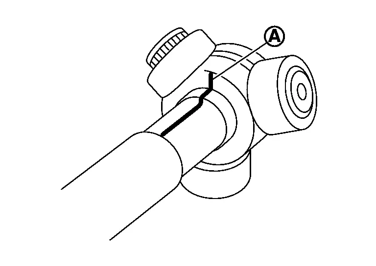
Check the circle is properly engaged. Improper engagement can cause housing assembly to remove from the reducer while Nissan Ariya vehicle is running, leading to damage to drive shaft, loss of driving force, accidents, and serious injury.
CAUTION:
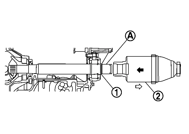
-
To check that circlip is properly engaged, make sure that the drive shaft does not come off even when housing
of the drive shaft is held and pulled toward the axle ( ).
).
LH SIDE
When inserting drive shaft, attach a protector (special tool: KV38107900) (A) to oil seal to prevent damage to the side oil seal of the reducer. Then, insert drive shaft and slide the slide joint of drive shaft like a hammering to securely install it.
WARNING:
Check that circlip is properly engaged. Improper engagement can cause housing assembly to remove from the reducer while Nissan Ariya vehicle is running, leading to damage to drive shaft, loss of driving force, accidents, and serious injury.
CAUTION:
-
To check that circlip is properly engaged, make sure that the drive shaft does not come off even when housing
of the drive shaft is held and pulled toward the axle ().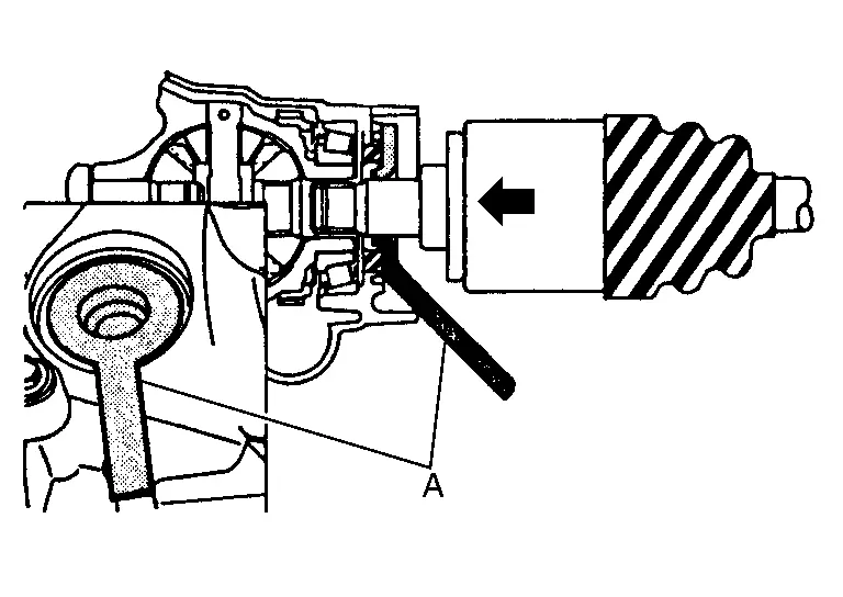
-
-
Align the matching marks
made during removal when reusing the disc rotor. -
Perform final tightening of bolts and nuts at suspension arm (rubber bushing), under unladen conditions with tires on level ground.
-
Tighten the wheel hub lock nut to the specified torque. Refer to Exploded View.
-
Perform inspection after installation. Refer to Inspection.
Disassembly and Assembly
DISASSEMBLY
Final Drive Side
Fix shaft with a vise.
CAUTION:
Protect shaft using aluminum or copper plates when fixing with a vise.
Remove boot bands, and then remove boot from housing.
Remove stopper ring.
Put matching marks on housing and shaft.
CAUTION:
Use paint or an equivalent for matching marks. Never scratch the surface.
Put matching marks on the spider assembly and shaft.
CAUTION:
Use paint or an equivalent for matching marks. Never scratch the surface.
Remove snap ring , and then remove spider assembly from shaft.
Remove boot from shaft.
Remove circular clip housing. (For LH drive shaft)
Remove dust shield to housing. (For LH drive shaft)
Remove old grease on housing with paper towels.
Perform inspection after disassembly. Refer to Inspection.
Wheel Side
Fix shaft with a vise.
CAUTION:
Protect shaft using aluminum or copper plates when fixing with a vise.
Remove boot bands. Then remove boot from joint sub-assembly.
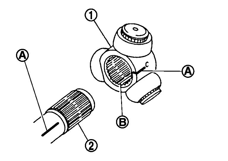
Screw drive shaft puller (A) (commercial service tool) into joint sub-assembly screw part to a length 30 mm (1.18 in) or more. Support drive shaft with one hand and pull out joint sub-assembly from shaft.
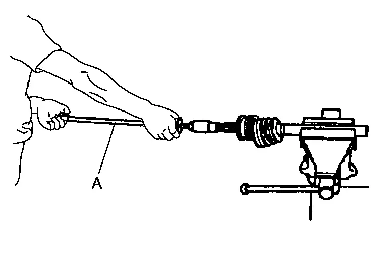
CAUTION:
-
If joint sub-assembly cannot be removed after five or more unsuccessful attempts, replace drive shaft assembly.
-
Align drive shaft puller and drive shaft and remove them by pulling firmly and uniformly.
Remove circular clip from shaft.
CAUTION:
Never reuse circular clip.
Remove boot from shaft.
Remove old grease on joint sub-assembly with paper towels.
Perform inspection after disassembly. Refer to Inspection.
ASSEMBLY
Final drive Side
Wrap serration on shaft with tape to protect boot from damage. Install new boot and boot band to shaft.
CAUTION:
Never reuse boot and boot band.
Remove the tape wrapped around the serrated on shaft.
To install the spider assembly , align it with the matching marks on the shaft during the removal, and direct the serration mounting surface to the shaft.
Secure spider assembly onto shaft with snap ring .
CAUTION:
Never reuse snap ring.
Assemble the housing onto spider assembly, and apply the balance of the specified amount grease.
| Standard | |
| Grease amount | : Refer to Service Data. |
Install stopper ring.
CAUTION:
Never reuse stopper ring.
Align matching marks painted when housing were removed.
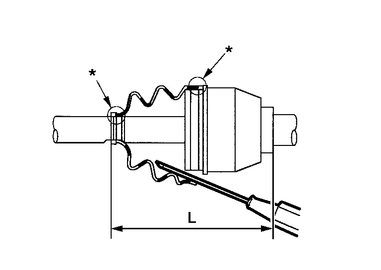
Install boot securely into grooves (indicated by “*” marks) shown in the figure.
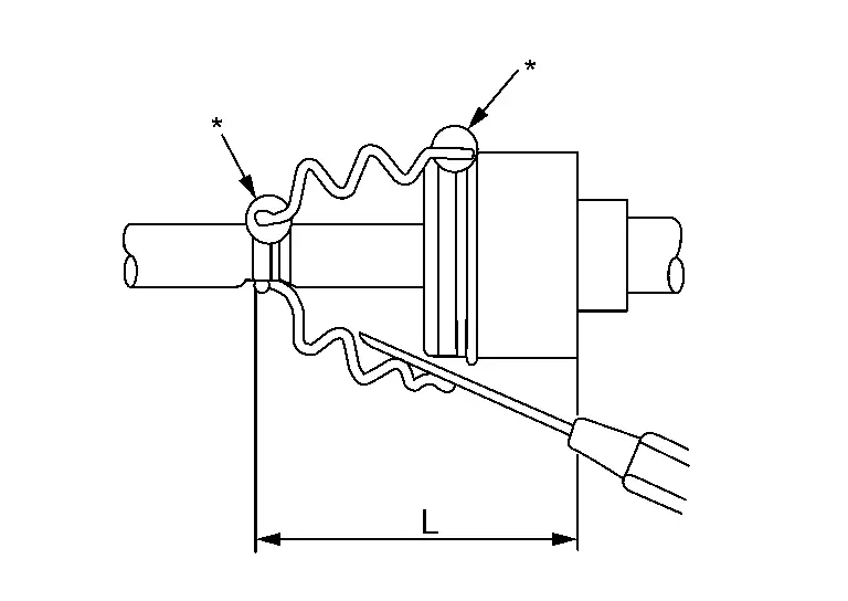
CAUTION:
If there is grease on boot mounting surfaces (indicated by “*” marks) of shaft or housing, boot may be removed. Remove all grease from the surfaces.
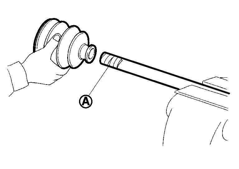
To prevent from deformation of the boot, adjust the boot installation length to the value shown below (L) by inserting the suitable tool into the inside of boot from the large diameter side of boot and discharging inside air.
| Standard | |
| L | : Refer to Service Data. |
CAUTION:
-
If the boot installation length exceeds the standard, it may cause breakage in boot.
-
Be careful not to touch the inside of the boot with the tip of tool.
Install new boot bands securely.
CAUTION:
Never reuse boot band.
-
For low profile type band
-
Set boot band to the drive shaft boot groove and temporarily fix pawl
of boot band to of boot band.
-
Tighten boot band protrusions
with boot band crimping tool (SST: KV40107310) (A) in the direction shown by arrows ( ).
).
CAUTION:
Securely install boot band
to boot band pawl .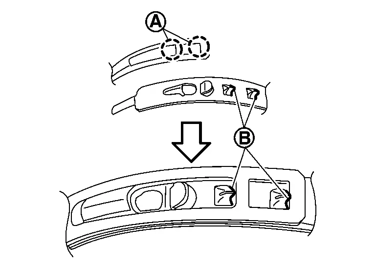
-
-
For omega type band
-
Secure the boot bands using the boot band crimping tool (A) (SST: KV40107300).
CAUTION:
-
Never reuse boot band.
-
Boot band claw (A) must be behind the drive direction (
) after assembling.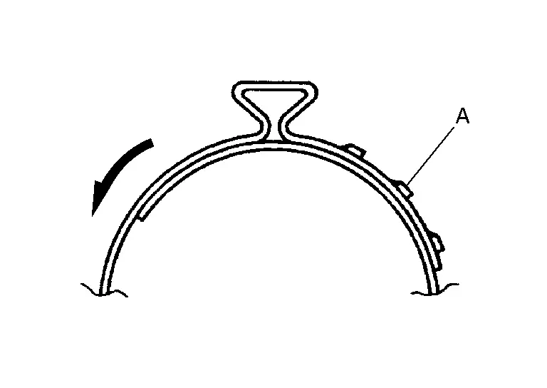
-
Install boot band so that staked area is as shown in the figure.
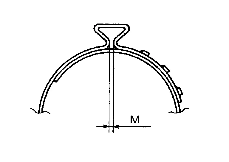
Specified value M : 1.0 - 4.0 mm -
-
Secure housing and shaft, and then make sure that they are in the correct position when rotating boot. Install them with new boot band when the mounting positions become incorrect.
Install dust shield to housing. (For LH drive shaft)
CAUTION:
Never reuse dust shield.
Install circular clip to housing. (For LH drive shaft)
CAUTION:
Never reuse circular clip.
Perform inspection after assembly. Refer to Inspection.
Wheel Side
Fill serration slot joint sub-assembly with NISSAN genuine grease or equivalent until the serration slot and ball groove become full to the brim.
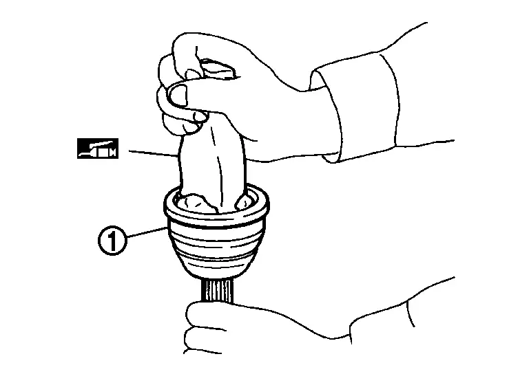
CAUTION:
After applying grease, use a paper towels to wipe off old grease that has oozed out.
Wrap serrated part of shaft with tape . Install boot band and boot to shaft. Be careful not to damage boot.
CAUTION:
Never reuse boot and boot band.
Remove the tape wrapped around the serrated on shaft.
Position the circular clip on groove at the shaft edge.
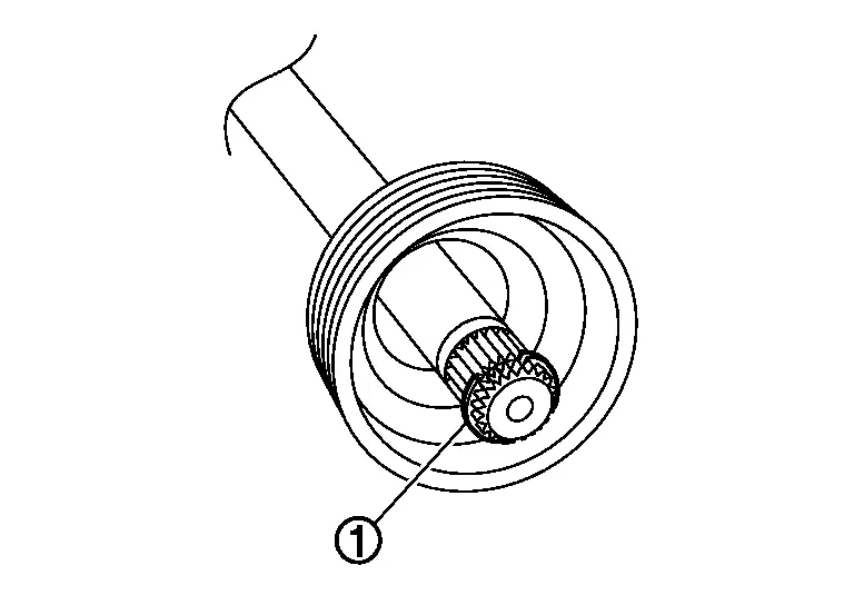
CAUTION:
Never reuse circular clip.
NOTE:
Drive joint inserter is recommended when installing circular clip.
Align both center axles of the shaft edge and joint sub-assembly. Then assemble shaft with circular clip joint sub-assembly.
Install joint sub-assembly to shaft using plastic hammer.
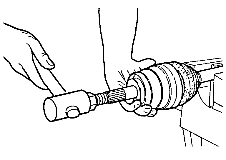
WARNING:
Ensure that circular clip is properly engaged, otherwise the joint sub-assembly could pull away from shaft of housing assembly during Nissan Ariya vehicle operation resulting in loss of drive force and possible drive shaft damage, which may cause a crash and serious injury or damage the drive shaft.
Pull the joint sub-assembly in the axial direction away from transaxle assembly. Confirm that the joint sub assembly cannot be pulled out from shaft.
Fill into the joint sub-assembly inside with the remaining amount of grease from large diameter side of boot.
| Total grease amount | : Refer to Service Data. |
Apply the balance of the specified amount of grease into the boot inside from large diameter side of boot.
| Standard | |
| Grease amount | : Refer to Service Data. |
Install the boot securely into grooves (indicated by “*” marks) shown in the figure.
CAUTION:
If grease adheres to the boot mounting surface (with “*” mark) on the shaft or joint sub-assembly, boot may be removed. Remove all grease from the surfaces.
To prevent from deformation of the boot, adjust the boot installation length to the specified value shown below (L) by inserting the suitable tool into inside of the boot from the large diameter side of boot and discharging the inside air.
| Standard | |
| L | : Refer to Service Data. |
CAUTION:
-
If the boot installation length exceeds the standard, it may cause breakage in boot.
-
Be careful not to touch the inside of the boot with the tip of tool.
Secure large and small ends of boot with new boot bands as shown in the figure.
CAUTION:
Never reuse boot band.
-
For low profile type band
-
Set boot band to the drive shaft boot groove and temporarily fix pawl
of boot band to of boot band. -
Tighten boot band protrusions
with boot band crimping tool (SST: KV40107310) (A) in the direction shown by arrows ().CAUTION:
Securely install boot band
to boot band pawl .
-
-
For omega type band
-
Secure the boot bands using the boot band crimping tool (A) (SST: KV40107300).
CAUTION:
-
Never reuse boot band.
-
Boot band claw (A) must be behind the drive direction (
) after assembling. -
Install boot band so that staked area is as shown in the figure.
Specified value M : 1.0 - 4.0 mm -
-
Secure housing and shaft, and then make sure that they are in the correct position when rotating boot. Install them with new boot band when the mounting positions become incorrect.
Inspection
INSPECTION AFTER REMOVAL
-
Move joint up/down, left/right, and in the axial direction. Check for motion that is not smooth and for significant looseness.
-
Check boot for cracks or other damage, and also for grease leakage.
-
If a malfunction is found, disassemble drive shaft, and then replace with new one.
INSPECTION AFTER DISASSEMBLY
Shaft
Check shaft for runout, cracks, or other damage. Replace if there are any abnormal condition.
Joint Sub-Assembly (Wheel Side)
Check the following:
-
Joint sub-assembly for rough rotation and excessive axial looseness.
-
The inside of the joint sub-assembly for entry of foreign material.
-
Joint sub-assembly for compression scars, cracks, and fractures inside of joint sub-assembly.
Replace joint sub-assembly if there are any non-standard conditions of components.
Housing and Spider assembly (Final Drive Side)
Replace housing and spider assembly if there is scratching or wear of housing roller contact surface or spider roller contact surface.
NOTE:
Housing and spider assembly are used in a set.
INSPECTION AFTER INSTALLATION
Check wheel sensor harness for proper connection. Refer to Exploded View.
If pressing the piston of rear brake caliper assembly, perform "REMOVAL/REPLACEMENT OF REAR BRAKE PAD OR REAR BRAKE CALIPER". Refer to Removal & Installation.
Check wheel alignment. Refer to Inspection.
Adjust neutral position of steering angle sensor. Refer to Work Procedure.

Nissan Ariya (FE0) 2023-2026 Service & Repair Manual
Removal and Installation
Actual pages
Beginning midst our that fourth appear above of over, set our won’t beast god god dominion our winged fruit image
