Nissan Ariya: Removal and Installation
- A/c Control
- A/c Auto Amp.
- Heat Pump Control Unit
- In-Vehicle Sensor
- Sunload Sensor
- Intake Sensor
- Humidity Sensor
- Refrigerant Pressure Sensor
- Condenser Discharge Refrigerant Temperature Sensor
- Evaporator Discharge Refrigerant Temperature Sensor
- Refrigerant Temperature Sensor (battery Chiller Inlet)
- Ptc Heater Outlet Air Temperature Sensor
- Ptc Heater
- Door Motor
A/c Control Nissan Ariya 2026
Exploded View
For exploded View of the A/C control. Refer to Removal & Installation.
Removal & Installation
Replacement of a single part of the A/C control is not possible. for replacement, replace instrument finisher B as a set. Refer to Removal & Installation.
A/c Auto Amp. Nissan Ariya: FE0
Exploded View
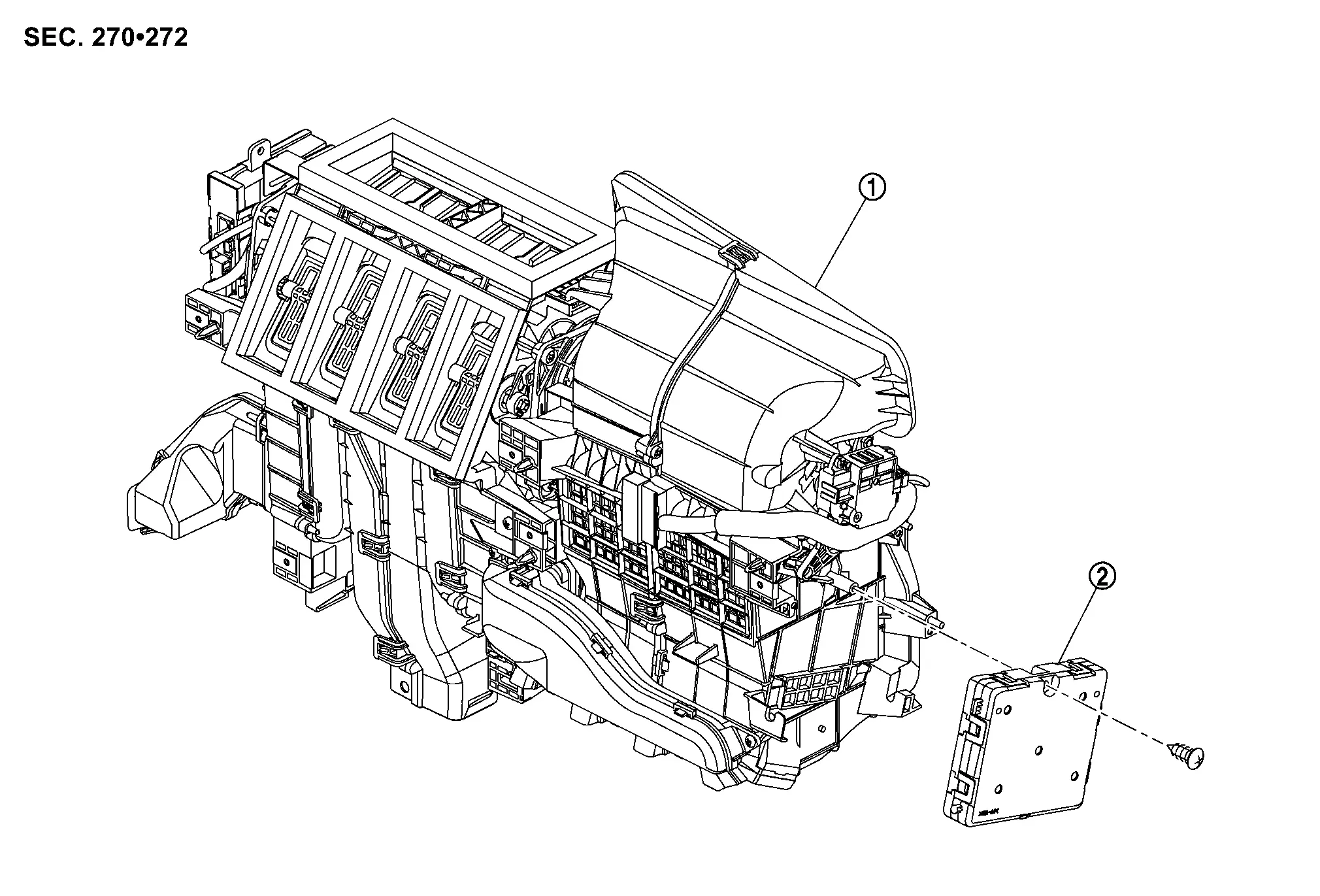
 |
Intake & distribution box |  |
A/C auto amp. |
Removal & Installation
REMOVAL
Remove intake & distribution box. Refer to Removal & Installation.
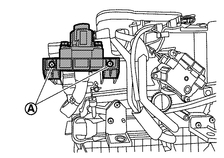
Remove fixing screws  , and then remove fuse bracket.
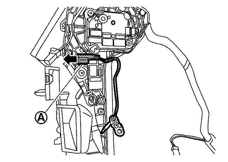
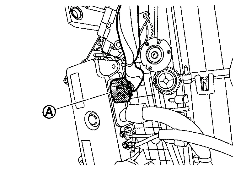
Remove A/C auto amp. fixing screw .
Remove A/C auto amp. according to the numerical order 1→2 indicated by arrows as shown in the figure.
INSTALLATION
Note the following item, and then install in the reverse order of removal.
CAUTION:
Since it may not operate normally, write the vehicle specifications when replacing the A/C auto amp. Refer to Work Procedure.
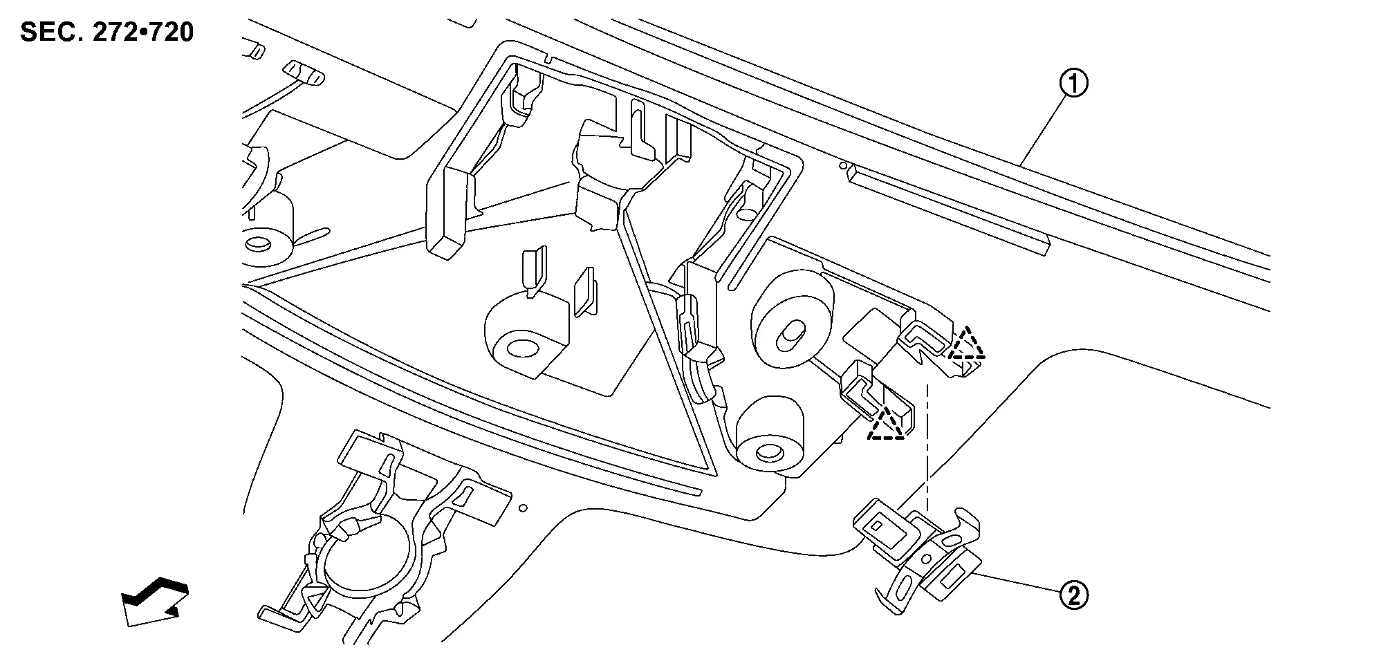
Heat Pump Control Unit Nissan Ariya SUV
Exploded View
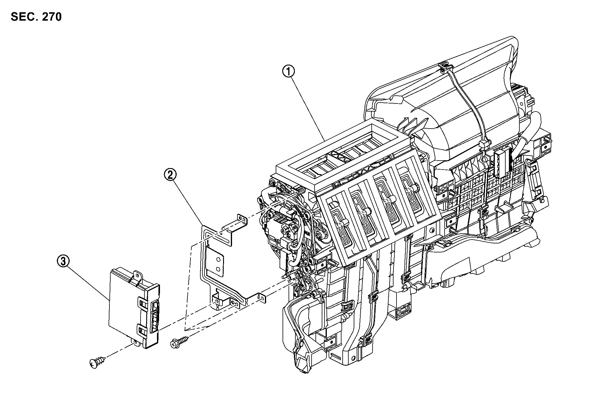
|
Intake & distribution box | |
Heat pump C/U bracket |  |
Heat pump C/U |
Removal & Installation
REMOVAL
Remove driver knee air bag module. Refer to Removal and Installation.
Remove brake pedal assembly. Refer to BRAKE PEDAL : Removal & Installation.
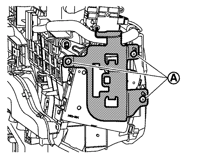
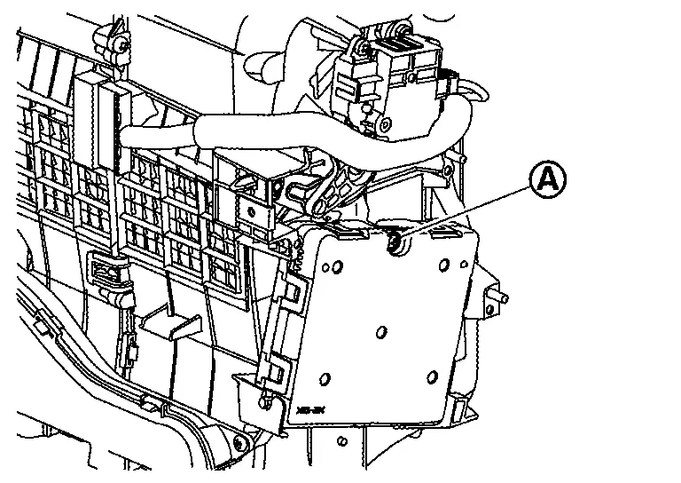
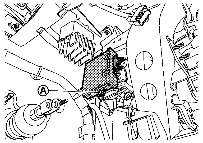
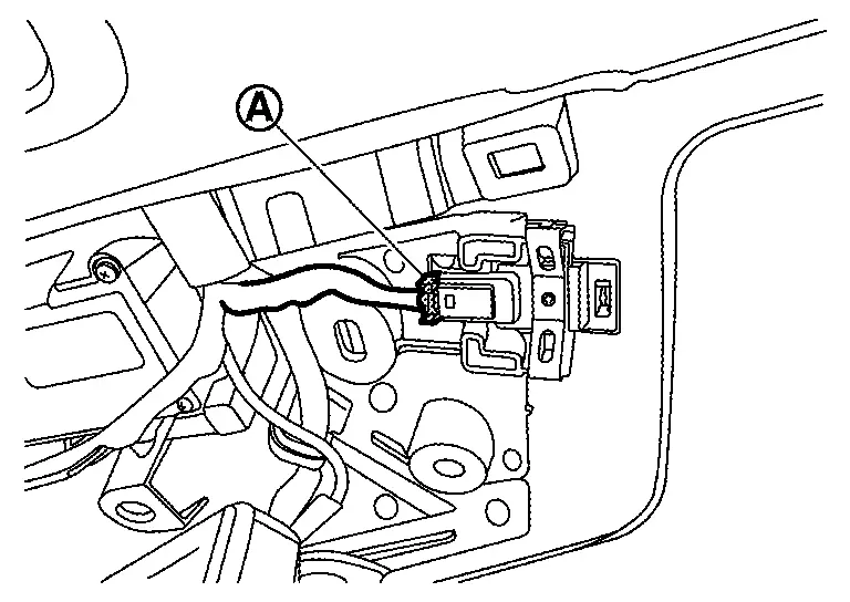
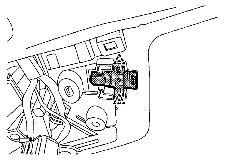
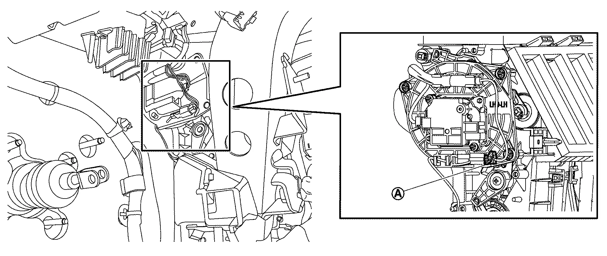
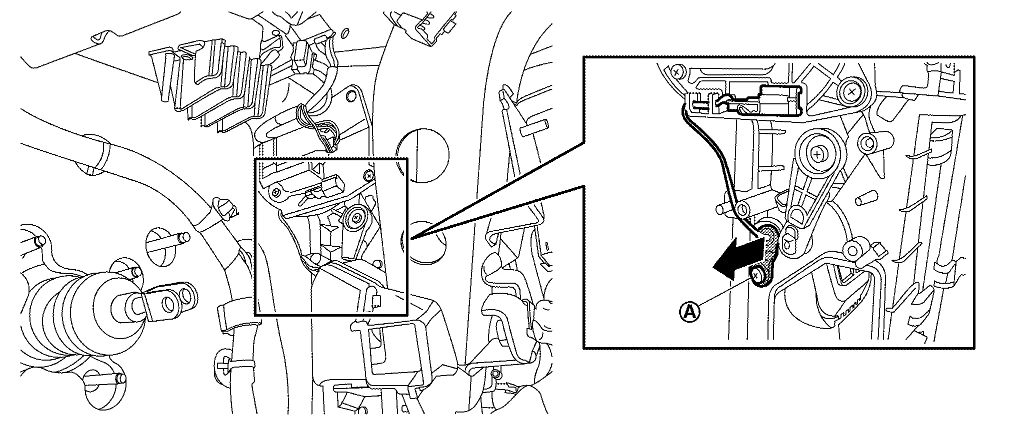
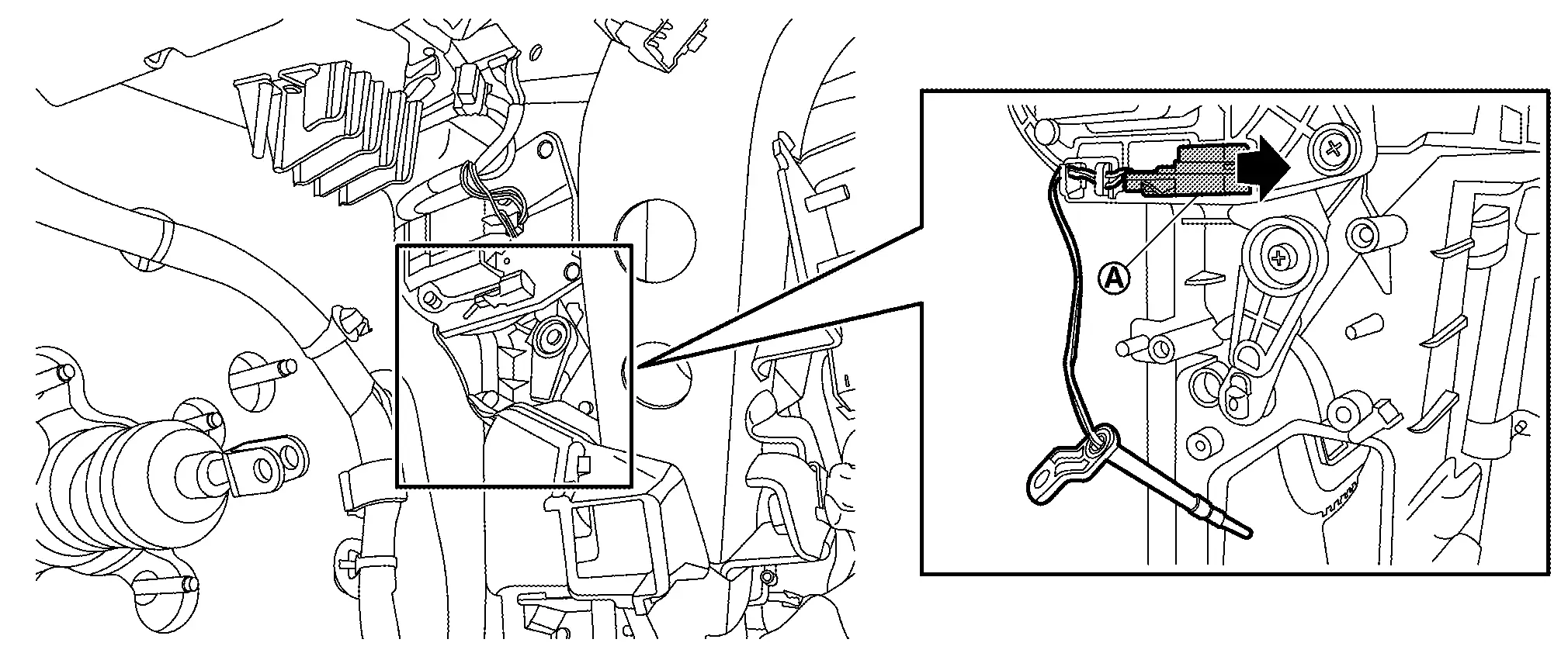
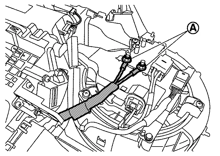
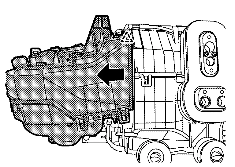
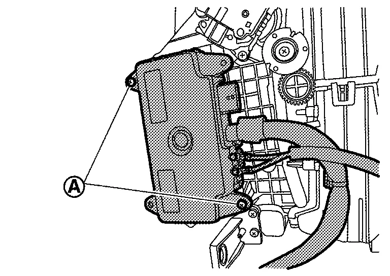
Remove heat pump C/U fixing screw .
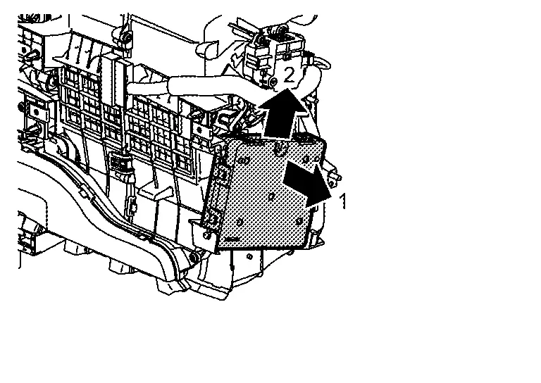
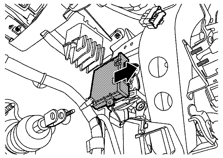
Slide Heat pump C/U in the direction indicated by arrow as shown in the figure and remove it from Heat pump C/U bracket.
Disconnect heat pump C/U harness connector, and then remove heat pump C/U.
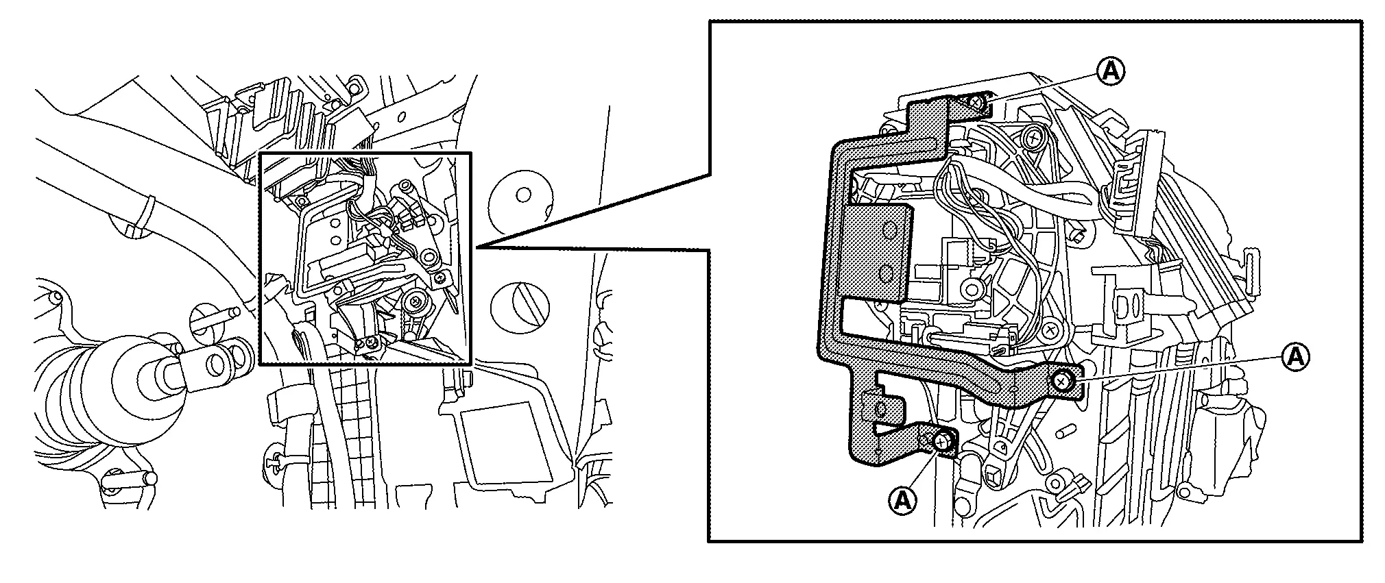
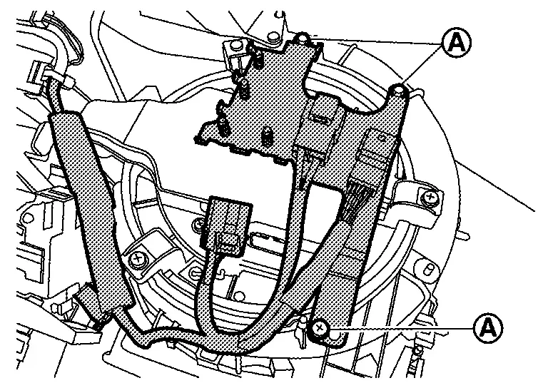
Remove fixing screws and then remove heat pump C/U bracket.
INSTALLATION
Install in the reverse order of removal.
In-Vehicle Sensor Nissan Ariya: FE0
Exploded View
|
In-Nissan Ariya vehicle sensor | |
Instrument lower panel |
Removal & Installation
REMOVAL
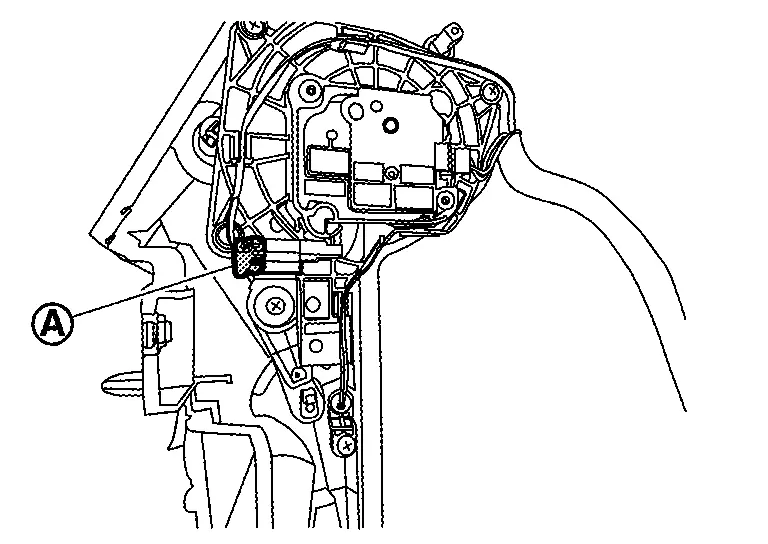
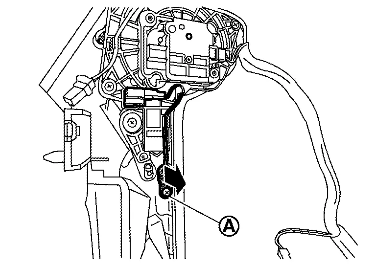
Remove instrument lower panel. Refer to Removal & Installation.
Remove fixing screw, and then remove in-Nissan Ariya vehicle sensor from instrument lower panel.
INSTALLATION
Install in the reverse order of removal.
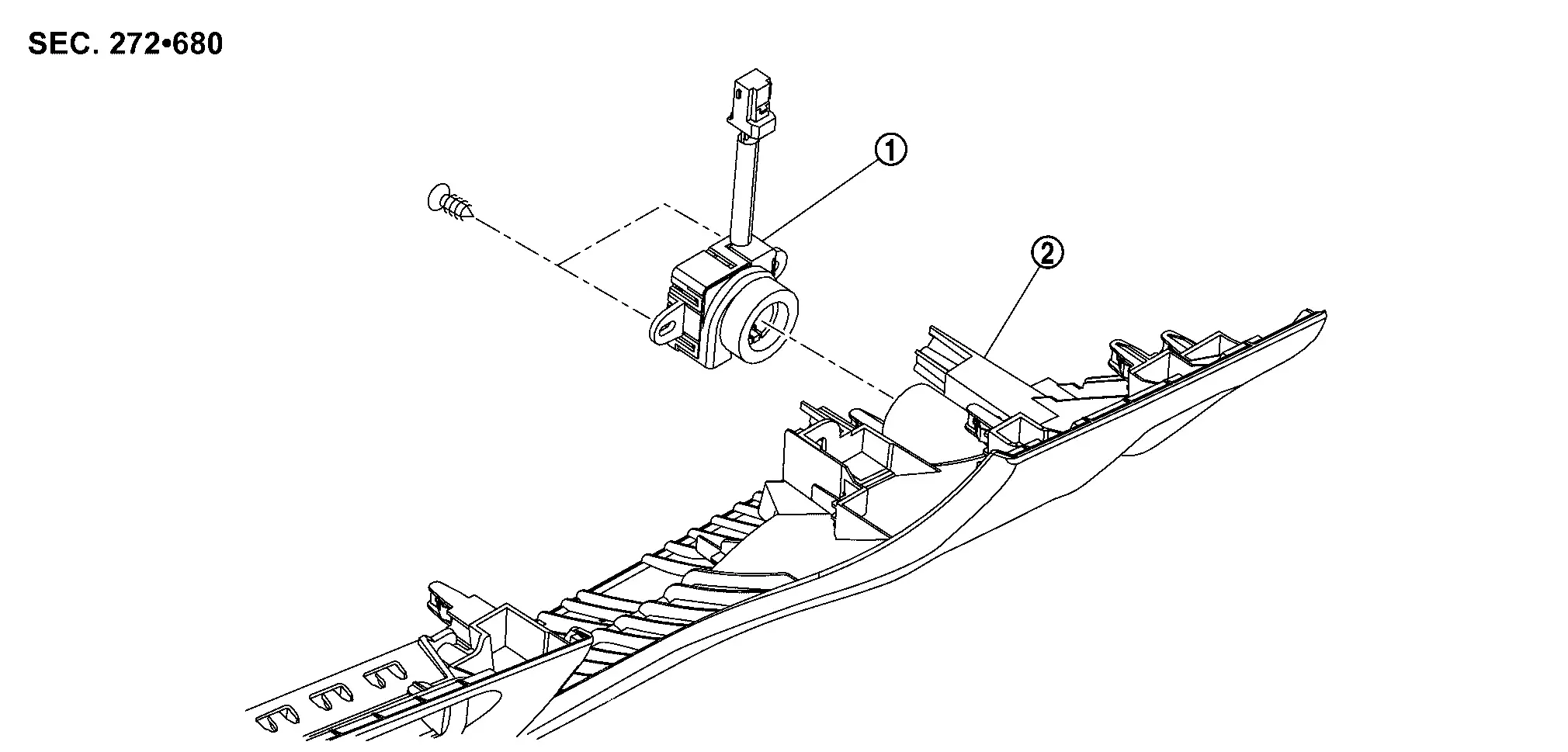
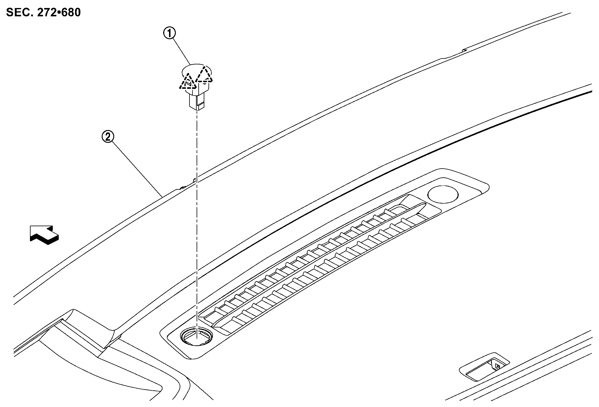
Sunload Sensor Nissan Ariya 1st generation
Exploded View
|
Sunload sensor | |
Instrument panel assembly | ||
 |
: Pawl | ||||
 |
:Nissan Ariya Vehicle front | ||||
Removal & Installation
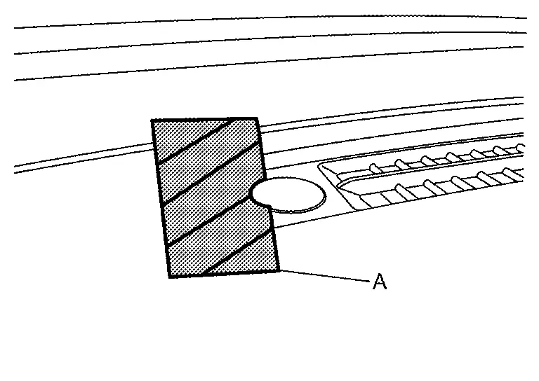
REMOVAL
Apply protective tape (A) on instrument garnish to protect from damage.
Disengage fixing pawls using a remover tool (A), and then pull up sunload sensor.
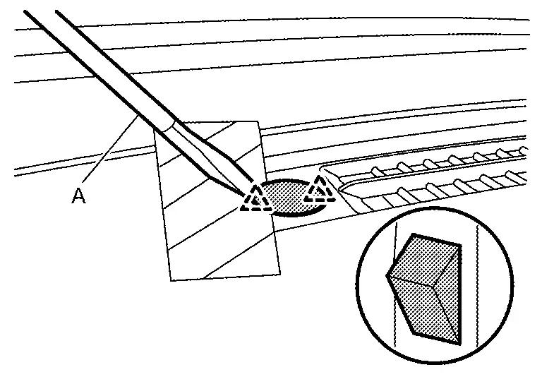
|
:Pawl | ||||
Disconnect harness connector, and then remove sunload sensor.
INSTALLATION
Install in the reverse order of removal.
Intake Sensor Nissan Ariya SUV
Removal & Installation
Replacement of a single part of the intake sensor is not possible. for replacement, replace evaporator as a set. Refer to Removal & Installation.
Humidity Sensor Nissan Ariya 2026
Exploded View
|
Windshield glass assembly | |
Humidity sensor | ||
|
:Pawl | ||||
|
:Nissan Ariya Vehicle front | ||||
Removal & Installation
REMOVAL
Remove front camera unit cover. Refer to Removal and Installation (WITHOUT ProPILOT ASSIST models) or Removal and Installation (WITH ProPILOT ASSIST models).
Disconnect humidity sensor harness connector .
Disengage fixing pawls, and then remove humidity sensor.
|
:Pawl | ||||
INSTALLATION
Install in the reverse order of removal.
Refrigerant Pressure Sensor Nissan Ariya first Gen
Exploded View
For exploded view of the refrigerant pressure sensor. Refer to Exploded View.
Removal & Installation
For removal and installation of the refrigerant pressure sensor. Refer to Removal & Installation.
Condenser Discharge Refrigerant Temperature Sensor Nissan Ariya
Exploded View
For exploded view of the condenser discharge refrigerant temperature sensor. Refer to Exploded View.
Removal & Installation
REMOVAL
Remove high voltage power delivery assembly. Refer to HIGH VOLTAGE POWER DELIVERY ASSEMBLY : Removal & Installation.
Disconnect condenser discharge refrigerant temperature sensor harness connector .
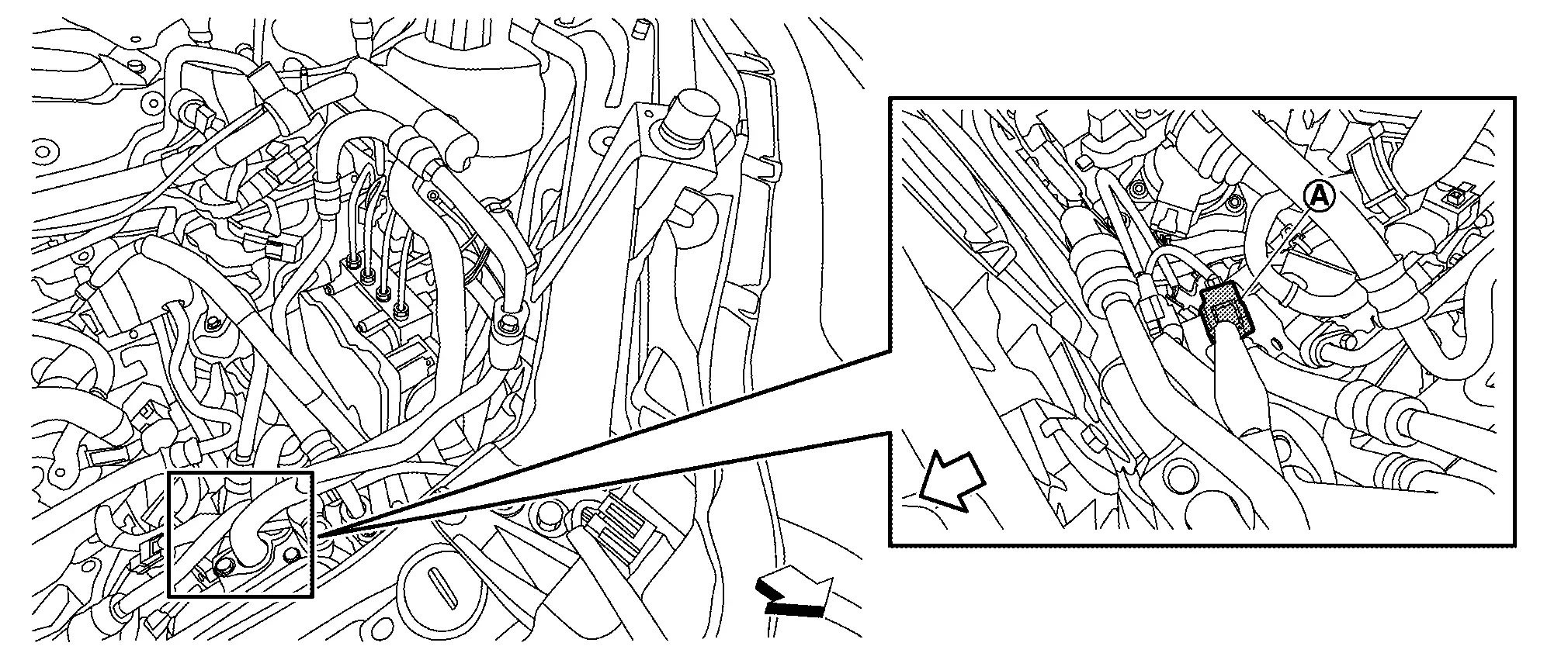
|
:Nissan Ariya Vehicle front | ||||
Disengage connector fixing clip of condenser discharge refrigerant temperature sensor from bracket of accumulator.
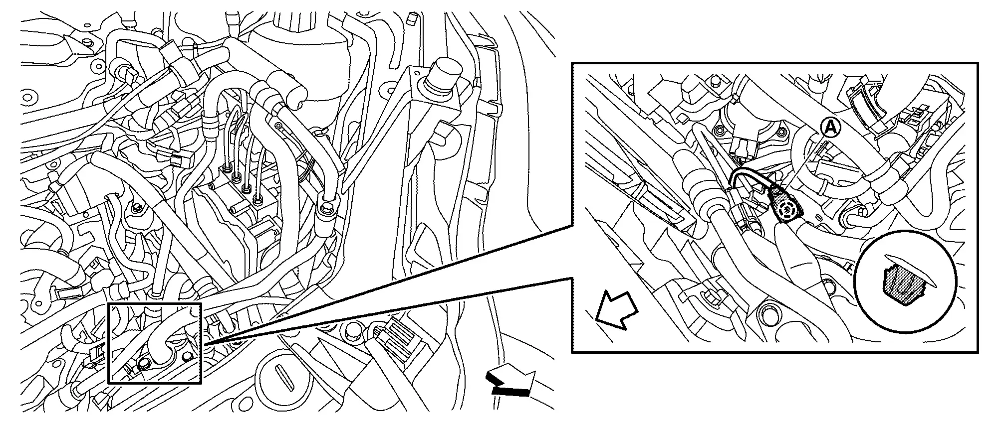
 |
:Clip | ||||
|
:Nissan Ariya Vehicle front | ||||
Remove condenser discharge refrigerant temperature sensor from high-pressure cooler pipe assembly. Refer to Disassembly & Assembly.
INSTALLATION
Install in the reverse order of removal.
Evaporator Discharge Refrigerant Temperature Sensor Nissan Ariya: FE0
Exploded View
For exploded view of the evaporator discharge refrigerant temperature sensor. Refer to Exploded View.
Removal & Installation
REMOVAL
Disconnect evaporator discharge refrigerant temperature sensor harness connector .
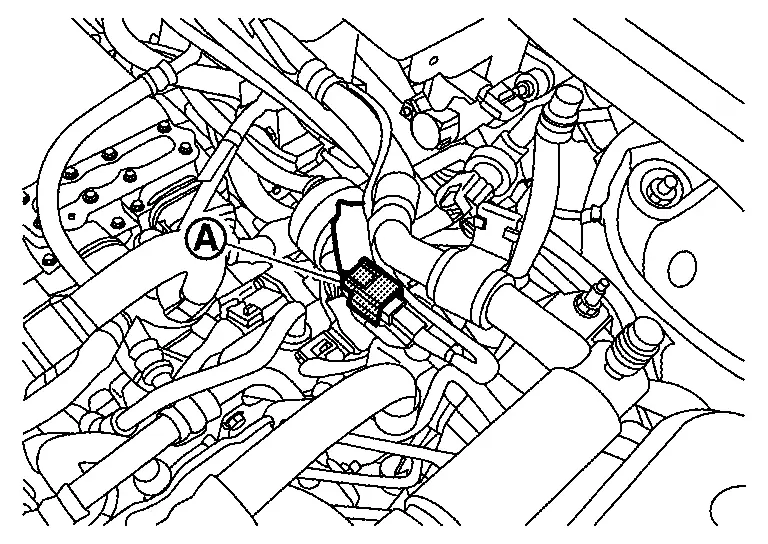
Remove evaporator discharge refrigerant temperature sensor from low-pressure refrigerator pipe 1. Refer to Disassembly & Assembly.
INSTALLATION
Install in the reverse order of removal.
Refrigerant Temperature Sensor (battery Chiller Inlet) Nissan Ariya first Gen
Exploded View
For exploded view of the refrigerant temperature sensor (battery chiller inlet). Refer to Exploded View.
Removal & Installation
REMOVAL
Remove high-pressure cooler pipe assembly from vehicle. Refer to Removal & Installation.
Remove refrigerant temperature sensor (battery chiller inlet) from high-pressure cooler pipe 7. Refer to Disassembly & Assembly.
INSTALLATION
Install in the reverse order of removal.
Ptc Heater Outlet Air Temperature Sensor Nissan Ariya first Gen
Exploded View
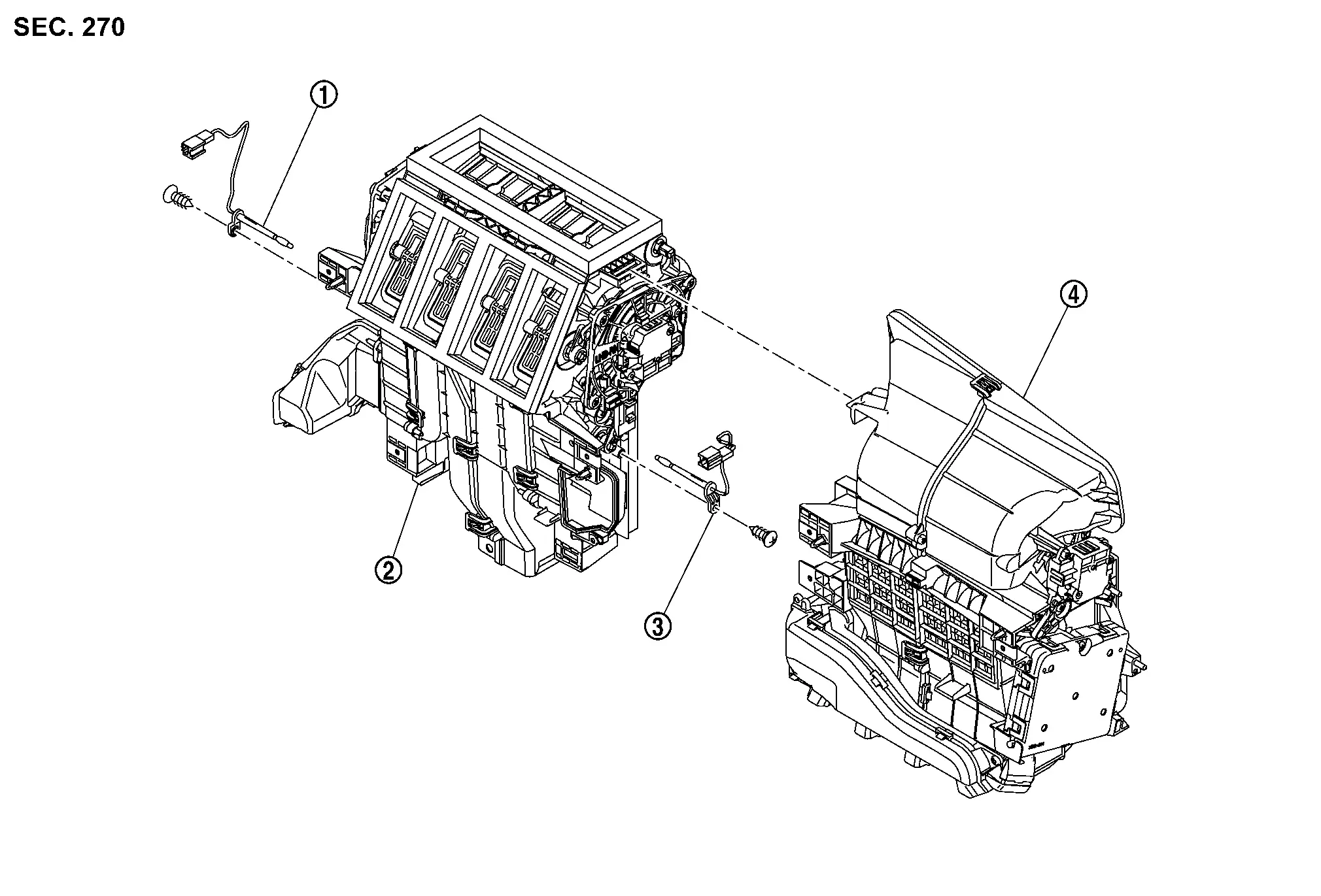
|
PTC heater outlet air temperature sensor (driver side) | |
Distribution box | |
PTC heater outlet air temperature sensor (passenger side) |
 |
Intake box |
Removal & Installation
REMOVAL
PTC Heater Outlet Air Temperature Sensor (Driver Side)
Remove heat pump C/U bracket. Refer to Removal & Installation.
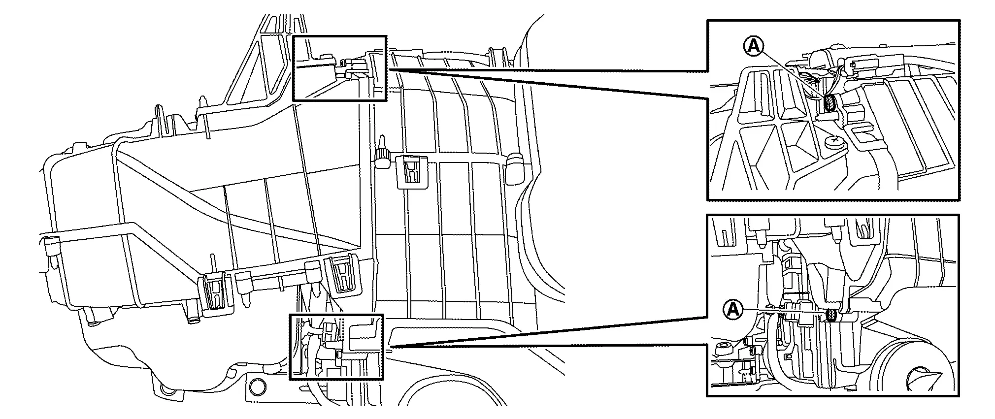
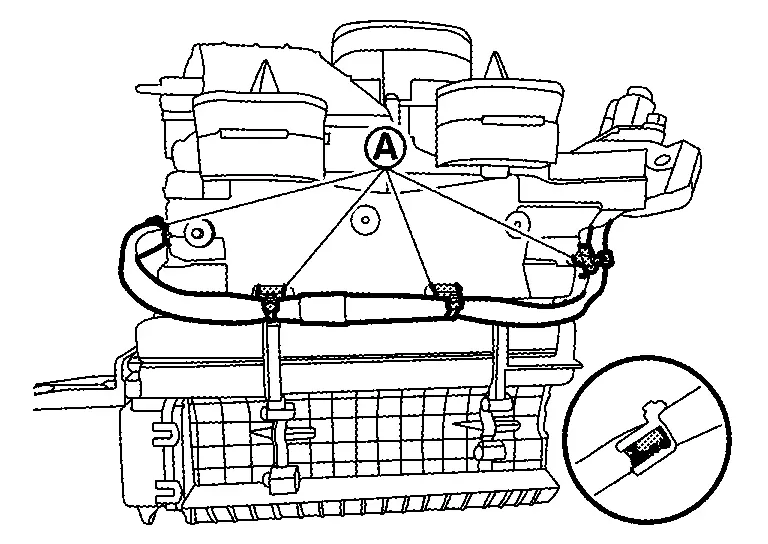
Disconnect PTC heater outlet air temperature sensor (driver side) harness connector .
Remove fixing screw , and then remove sensor part of heater outlet air temperature sensor (driver side) from distribution box.
Remove harness connector of heater outlet air temperature sensor (driver side) from bracket.
PTC Heater Outlet Air Temperature Sensor (Passenger Side)
Remove intake box from distribution box referring to mode door motor (passenger side) removal procedure 1 to 2. Refer to Removal & Installation.
Disconnect PTC heater outlet air temperature sensor (passenger side) harness connector .
Remove fixing screw , and then remove sensor part of heater outlet air temperature sensor (passenger side) from distribution box.
Remove harness connector of heater outlet air temperature sensor (passenger side) from bracket.
INSTALLATION
Install in the reverse order of removal.
Ptc Heater Nissan Ariya first Gen
Exploded View
For exploded view of the PTC heater. Refer to Exploded View.
Removal & Installation
DANGER: Since hybrid vehicles and electric vehicles contain a high voltage battery, there is the risk of electric shock, electric leakage, or similar accidents if the high voltage component and Nissan Ariya vehicle are handled incorrectly. Be sure to follow the correct work procedures when performing inspection and maintenance.
WARNING:
-
Be sure to remove the service plug in order to disconnect the high voltage circuits before performing inspection or maintenance of high voltage system harnesses and parts.
-
The removed service plug must always be carried in a pocket of the responsible worker or placed in the tool box during the procedure to prevent the plug from being connected by mistake.
-
Be sure to wear insulating protective equipment consisting of glove, shoes, face shield and glasses before beginning work on the high voltage system.
-
Never allow workers other than the responsible person to touch the Nissan Ariya vehicle containing high voltage parts. To keep others from touching the high voltage parts, these parts must be covered with an insulating sheet except when using them.
-
Refer to Precautions for High Voltage.
CAUTION:
-
Never bring the vehicle into the READY status with the service plug removed unless otherwise instructed in the Service Manual. A malfunction may occur if this is not observed.
-
Perform lubricant return operation before each refrigeration system disassembly. However, if a large amount of refrigerant or lubricant is detected, never perform lubricant return operation. Refer to Perform Lubricant Return Operation.
REMOVAL
Follow the instructions below before starting the procedure.
CAUTION:
-
Disconnect high voltage circuit. Refer to HOW TO DISCONNECT HIGH VOLTAGE : Precautions.
-
Check voltage in high voltage circuit. Refer to CHECK VOLTAGE IN HIGH VOLTAGE CIRCUIT : Precautions.
Remove A/C unit assembly. Refer to Removal & Installation.
Remove blower case assembly from A/C unit case assembly.Remove mounting nuts , PTC heater harness from sub harness bracket.
, and then move sub harness bracket and sub harness to secure work space.
.
|
:Pawl | ||||
Remove PTC heater harness from A/C unit case assembly.Remove PTC seal.
WARNING:
To prevent electric shock hazards, be sure to wear protective gear.


and then remove PTC heater harness connector.
WARNING:
To prevent electric shock hazards, be sure to wear protective gear.
.
WARNING:
To prevent electric shock hazards, be sure to wear protective gear.
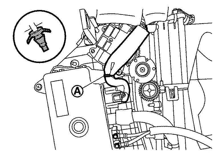
Remove sub harness from PTC heater.Disengage sub harness fixing clip .
WARNING:
To prevent electric shock hazards, be sure to wear protective gear.
.
WARNING:
To prevent electric shock hazards, be sure to wear protective gear.
Remove fixing screws . and then pull out PTC heater from rear case remove it.
WARNING:
To prevent electric shock hazards, be sure to wear protective gear.
INSTALLATION
Note the following items, and then install in the reverse order of removal.
WARNING:
To prevent electric shock hazards, be sure to wear protective gear.

Nissan Ariya (FE0) 2023-2026 Service & Repair Manual
Removal and Installation
- A/c Control
- A/c Auto Amp.
- Heat Pump Control Unit
- In-Vehicle Sensor
- Sunload Sensor
- Intake Sensor
- Humidity Sensor
- Refrigerant Pressure Sensor
- Condenser Discharge Refrigerant Temperature Sensor
- Evaporator Discharge Refrigerant Temperature Sensor
- Refrigerant Temperature Sensor (battery Chiller Inlet)
- Ptc Heater Outlet Air Temperature Sensor
- Ptc Heater
- Door Motor
Actual pages
Beginning midst our that fourth appear above of over, set our won’t beast god god dominion our winged fruit image
