Nissan Ariya: Removal and Installation
- Headlamp
- Front Combination Lamp
- Front Fog Lamp
- Side Turn Signal Lamp
- Light & Rain Sensor
- Lighting & Turn Signal Switch
- Hazard Switch
- Optical Sensor
- Headlamp Aiming Switch
- Rear Combination Lamp (body Side)
- Rear Combination Lamp (back Door Side)
- License Plate Lamp
- Rear Reflex Reflector
Headlamp Nissan Ariya 2026
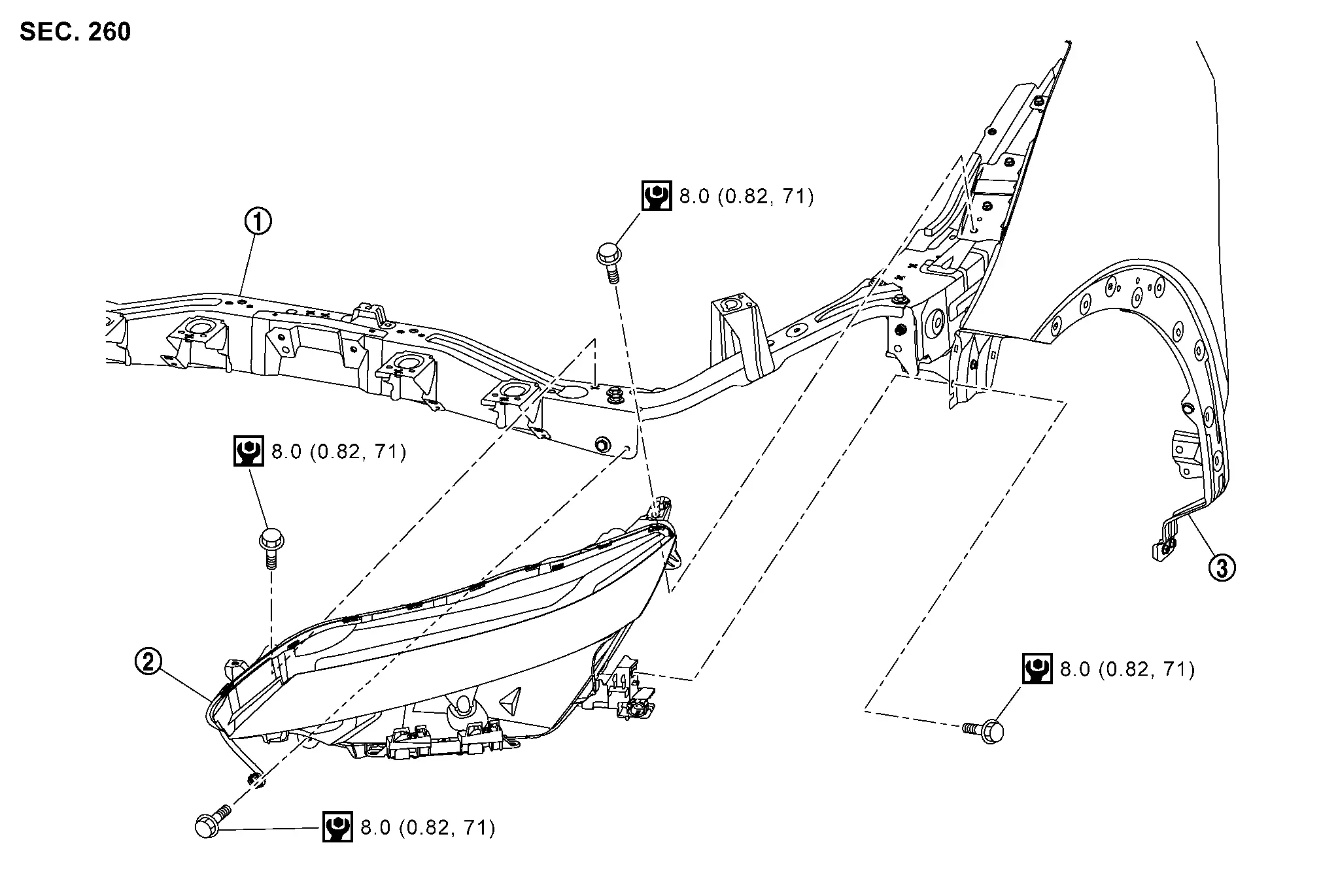
Exploded View
 |
Radiator core support |  |
Headlamp |  |
Front fender assembly |
 |
: N·m (kg-m, in-lb) | ||||
Removal & Installation
CAUTION:
Disconnect the battery negative terminal or remove power circuit fuse when performing the operation for preventing electric leakage. Refer to PRECAUTIONS FOR REMOVING BATTERY TERMINAL : Precautions.
REMOVAL
Remove front bumper fascia. Refer to Removal & Installation.
Remove headlamp mounting bolts.
Pull out headlamp forward the Nissan Ariya vehicle.
Disconnect headlamp harness connectors, and then remove headlamp.
INSTALLATION
Note the following item, and then install in the reverse order of removal.
CAUTION:
After installation, perform aiming adjustment. Refer to Adjustment.
Replacement
CAUTION:
Disconnect the battery negative terminal or remove power circuit fuse when performing the operation for preventing electric leakage. Refer to PRECAUTIONS FOR REMOVING BATTERY TERMINAL : Precautions.
HEADLAMP (Hi)
CAUTION:
Replacement of a single part is not possible due to the adoption of LED. For replacement, replace headlamp as a set.Refer to Removal & Installation.
HEADLAMP (Lo)
CAUTION:
Replacement of a single part is not possible due to the adoption of LED. For replacement, replace headlamp as a set.Refer to Removal & Installation.
FRONT SIDE MARKER LAMP
CAUTION:
Replacement of a single part is not possible due to the adoption of LED. For replacement, replace headlamp as a set.Refer to Removal & Installation.
Front Combination Lamp Nissan Ariya 2023
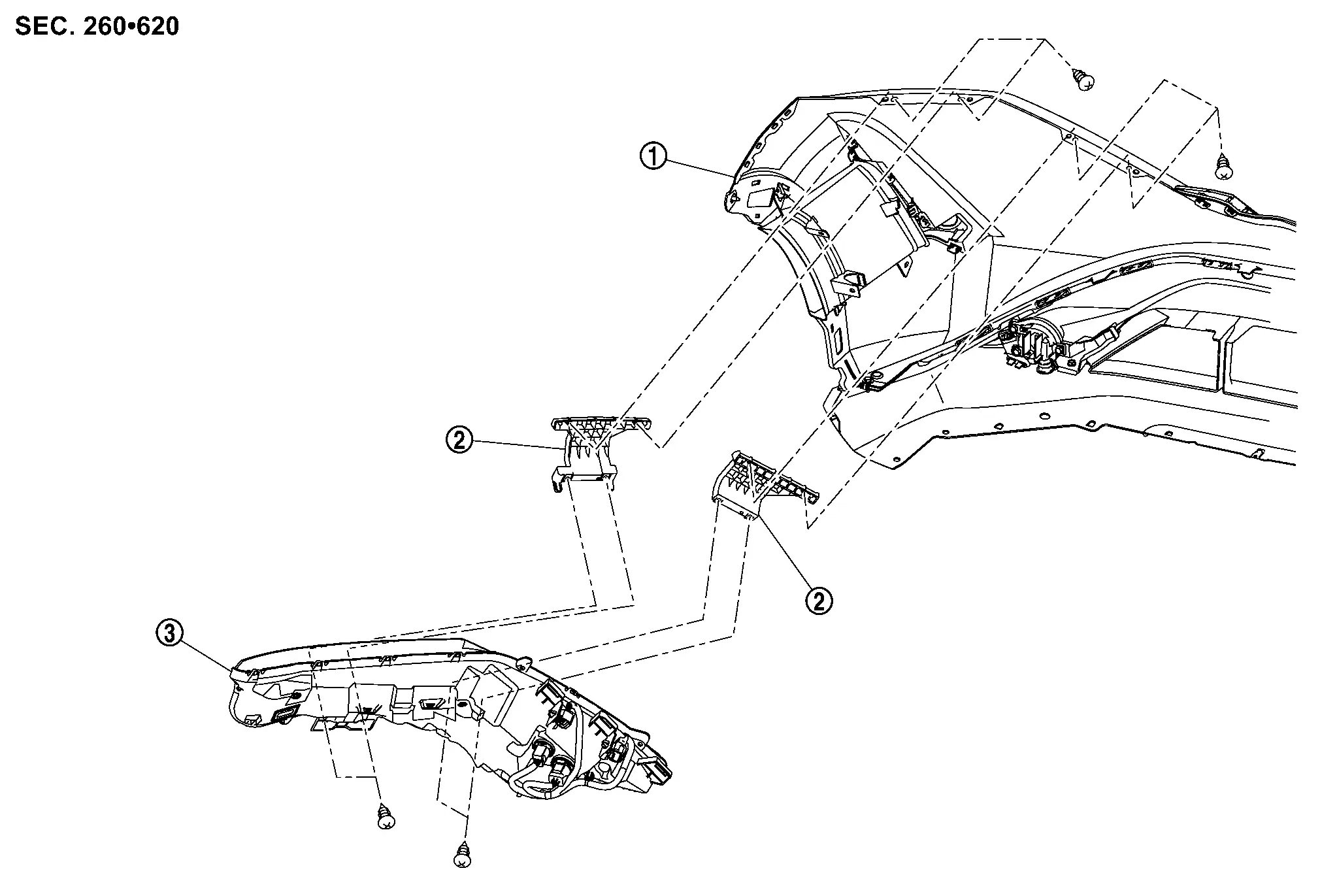
Exploded View
|
Front bumper fascia | |
Front combination lamp bracket | |
Front combination lamp |
Removal & Installation
CAUTION:
Disconnect the battery negative terminal or remove power circuit fuse when performing the operation for preventing electric leakage. Refer to PRECAUTIONS FOR REMOVING BATTERY TERMINAL : Precautions.
REMOVAL
Remove front bumper fascia. Refer to Removal & Installation.
Remove front combination lamp fixing screws, and then remove front combination lamp.
Remove front combination lamp bracket fixing screws, and then remove front combination lamp bracket.
INSTALLATION
Note the following item, and then install in the reverse order of removal.
Replacement
CAUTION:
Disconnect the battery negative terminal or remove power circuit fuse when performing the operation for preventing electric leakage. Refer to PRECAUTIONS FOR REMOVING BATTERY TERMINAL : Precautions.
PARKING LAMP
CAUTION:
Replacement of a single part is not possible due to the adoption of LED. For replacement, replace front combination lamp as a set. Refer to Removal & Installation.
DAYTIME RUNNING LIGHT
CAUTION:
Replacement of a single part is not possible due to the adoption of LED. For replacement, replace front combination lamp as a set. Refer to Removal & Installation.
FRONT TURN SIGNAL LAMP
CAUTION:
Replacement of a single part is not possible due to the adoption of LED. For replacement, replace front combination lamp as a set. Refer to Removal & Installation.
Front Fog Lamp Nissan Ariya 2026
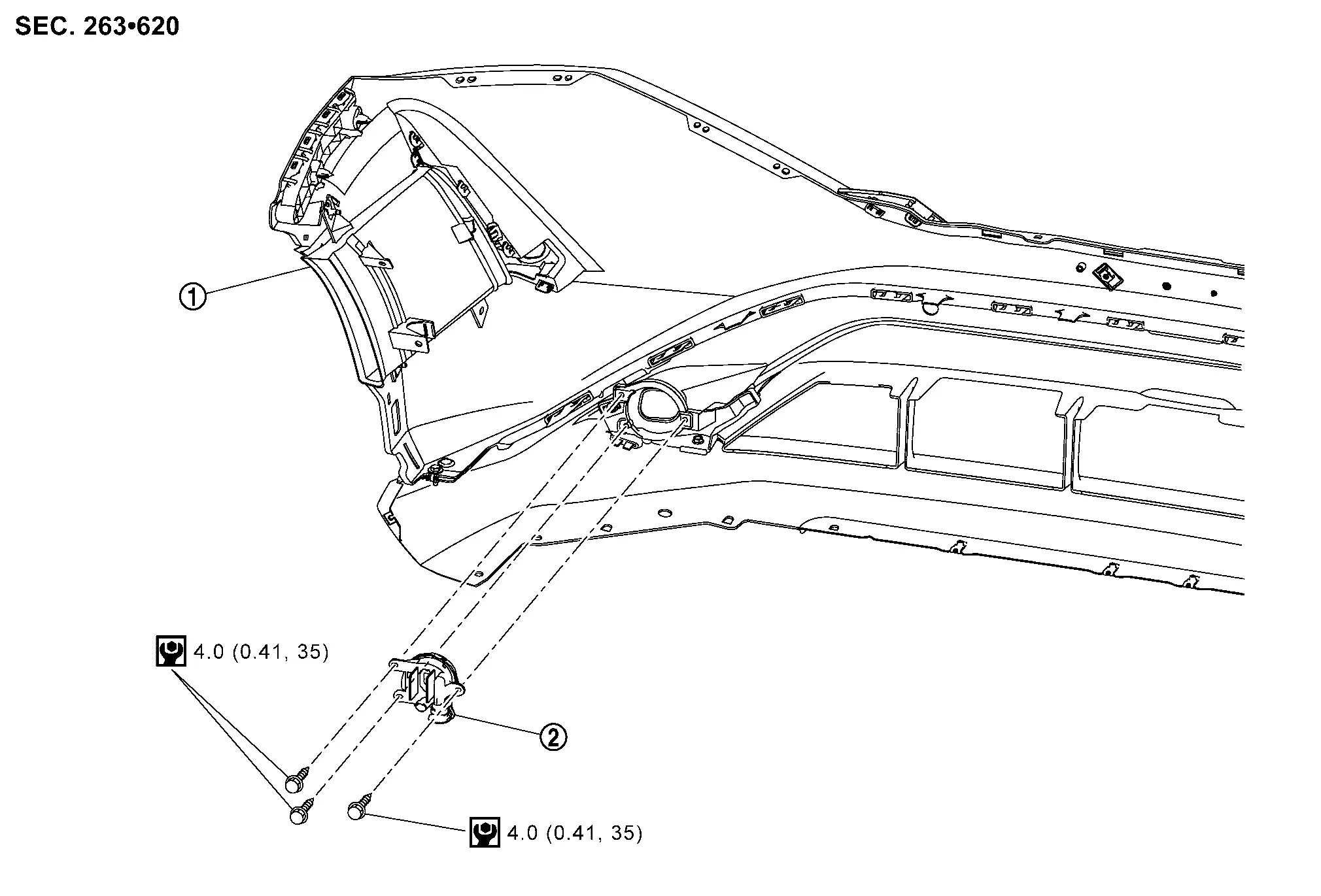
Exploded View
|
Front bumper fascia | |
Front fog lamp | ||
|
: N·m (kg-m, in-lb) | ||||
Removal & Installation
CAUTION:
Disconnect the battery negative terminal or remove power circuit fuse when performing the operation for preventing electric leakage. Refer to PRECAUTIONS FOR REMOVING BATTERY TERMINAL : Precautions.
REMOVAL
Remove front fender protector. Refer to Removal & Installation.
Disconnect front fog lamp harness connector.
Remove front fog lamp mounting bolts  , and then remove front fog lamp.
INSTALLATION
Note the following item, and then install in the reverse order of removal.
CAUTION:
After installation, perform aiming adjustment. Refer to Adjustment.
Replacement
CAUTION:
Disconnect the battery negative terminal or remove power circuit fuse when performing the operation for preventing electric leakage. Refer to PRECAUTIONS FOR REMOVING BATTERY TERMINAL : Precautions.
FRONT FOG LAMP
CAUTION:
Replacement of a single part is not possible due to the adoption of LED. For replacement, replace front fog lamp as a set. Refer to Removal & Installation.
Side Turn Signal Lamp Nissan Ariya 2026
Exploded View
For exploded view of side turn signal lamp. Refer to Exploded View.
Removal & Installation
CAUTION:
Disconnect the battery negative terminal or remove power circuit fuse when performing the operation for preventing electric leakage. Refer to PRECAUTIONS FOR REMOVING BATTERY TERMINAL : Precautions.
REMOVAL
Remove door mirror finisher. Refer to Disassembly & Assembly.
Remove side turn signal lamp fixing pawls.
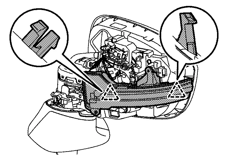
 |
: Pawl |
Disconnect side turn signal lamp harness connector, and then remove side turn signal lamp.
INSTALLATION
Install in the reverse order of removal.
Replacement
CAUTION:
Disconnect the battery negative terminal or remove power circuit fuse when performing the operation for preventing electric leakage. Refer to PRECAUTIONS FOR REMOVING BATTERY TERMINAL : Precautions.
SIDE TURN SIGNAL LAMP
CAUTION:
Replacement of a single part is not possible due to the adoption of LED. For replacement, replace side turn signal lamp as a set. Refer to Removal & Installation.
Light & Rain Sensor Nissan Ariya 2023
Exploded View
For exploded view of light & rain sensor. Refer to Exploded View.
Removal & Installation
REMOVAL
Remove light & rain sensor. Refer to Removal & Installation.
INSTALLATION
Install in the reverse order of removal.
Lighting & Turn Signal Switch Nissan Ariya 2023
Removal & Installation
REMOVAL
Remove lighting & turn signal switch (combination switch). Refer to Removal and Installation.
INSTALLATION
Install in the reverse order of removal.
Hazard Switch Nissan Ariya 1st generation
Removal & Installation
REMOVAL
Hazard switch is assembly part with multi function switch . Refer to Removal & Installation.
INSTALLATION
Install in the reverse order of removal.
Optical Sensor Nissan Ariya 1st generation
Exploded View
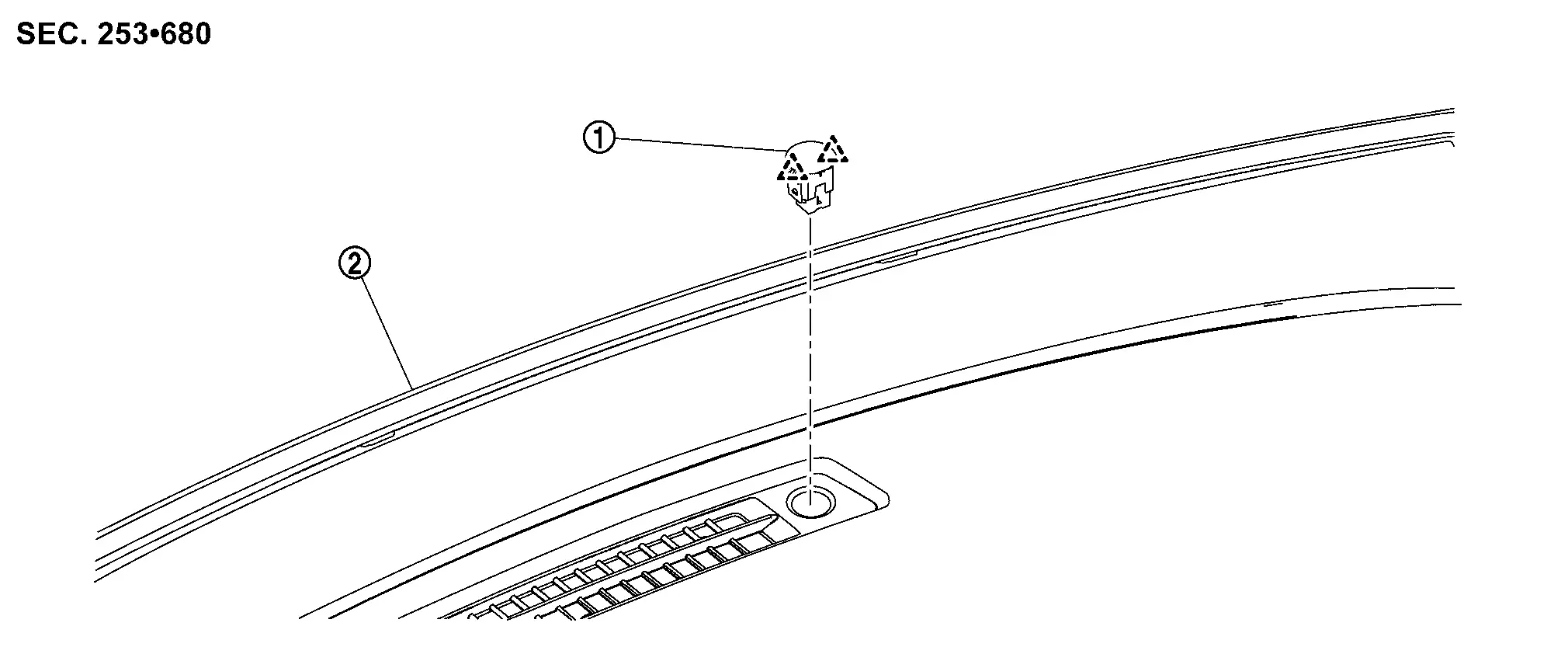
|
Optical sensor | |
Instrument garnish | ||
|
: Pawl | ||||
Removal and Installation
CAUTION:
Disconnect the battery negative terminal or remove power circuit fuse when performing the operation for preventing electric leakage. Refer to PRECAUTIONS FOR REMOVING BATTERY TERMINAL : Precautions.
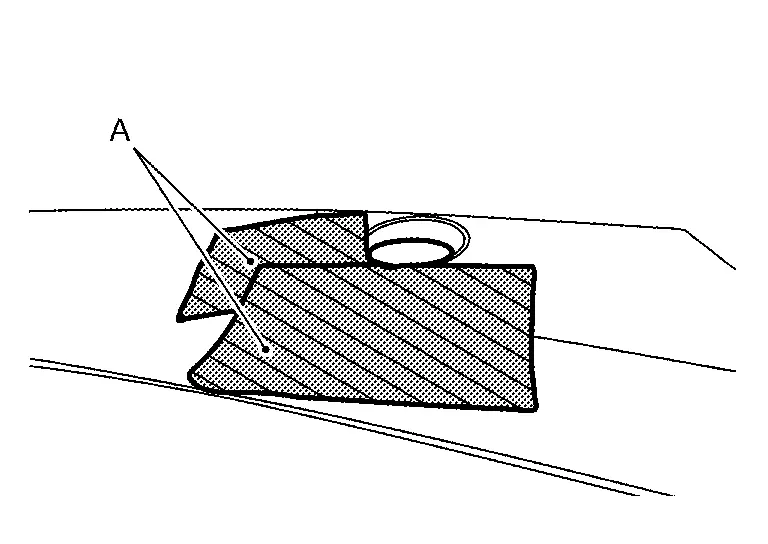
REMOVAL
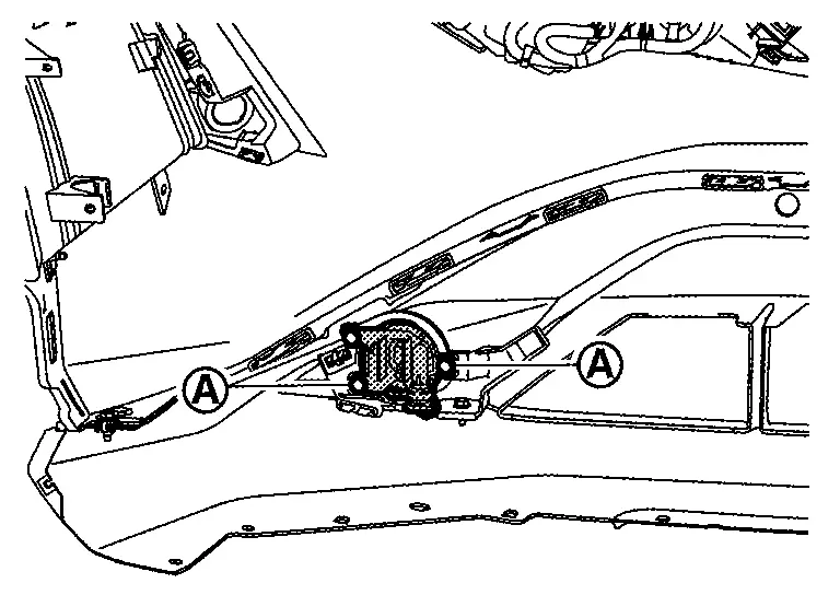
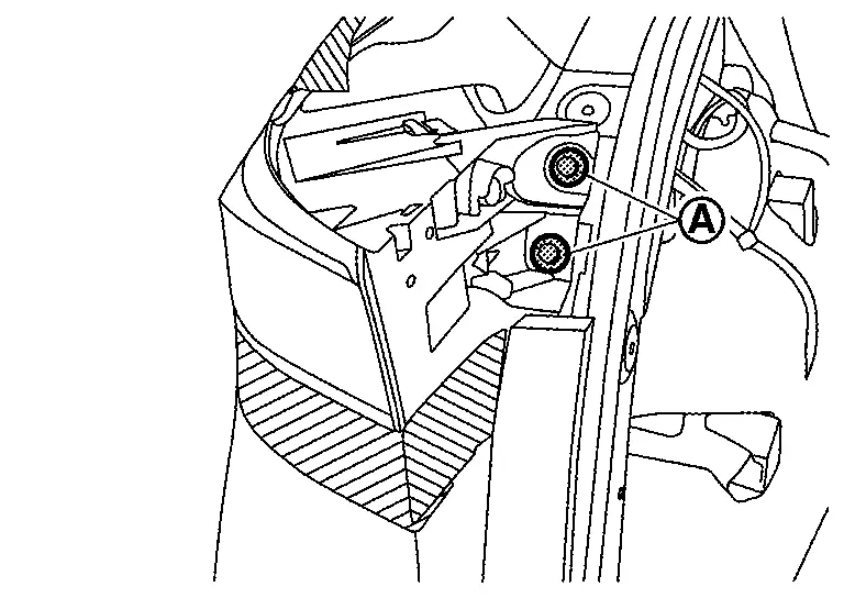
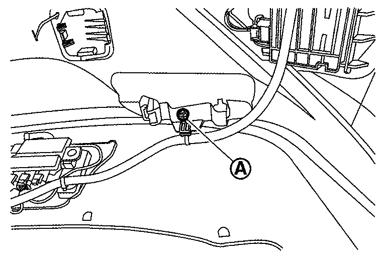
Apply protective tapes (A) on the part to protect it from damage.
Disengage optical sensor fixing pawls using a remover tool (A).
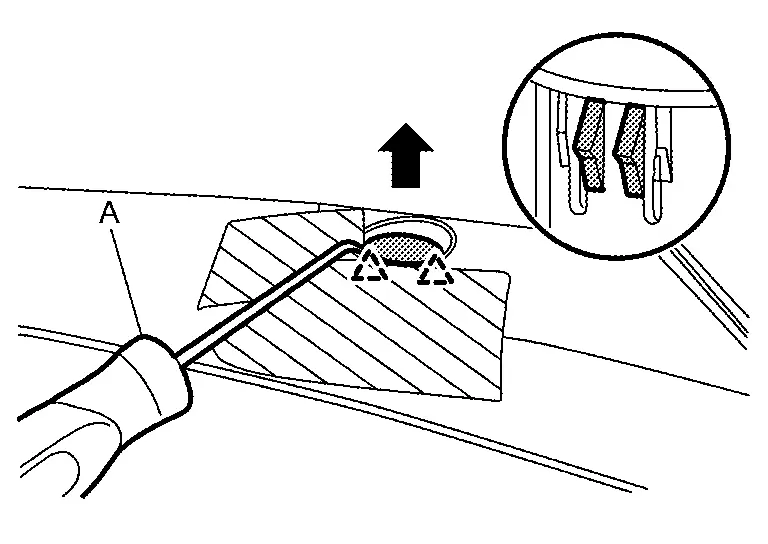
|
: Pawl |
Disconnect optical sensor harness connector, and then remove optical sensor.
INSTALLATION
Install in the reverse order of removal.
Headlamp Aiming Switch Nissan Ariya: FE0
Exploded View
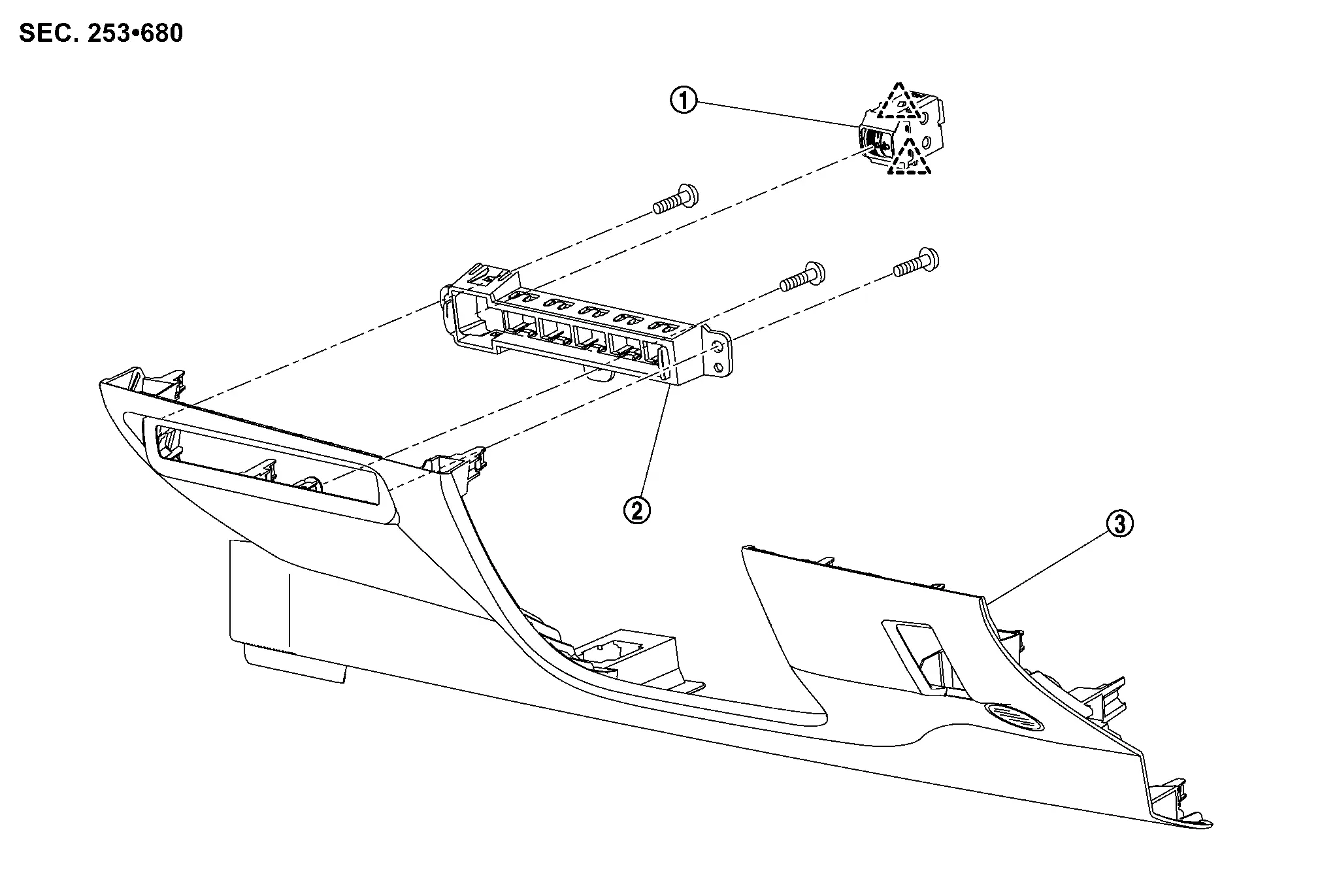
|
Headlamp aiming switch | |
Switch bracket |  |
Instrument lower panel |
|
: Pawl | ||||
Removal & Installation
CAUTION:
Disconnect the battery negative terminal or remove power circuit fuse when performing the operation for preventing electric leakage. Refer to PRECAUTIONS FOR REMOVING BATTERY TERMINAL : Precautions.
REMOVAL
Remove instrument lower panel. Refer to Exploded View.
Disengage headlamp aiming switch fixing pawls, and then remove headlamp aiming switch.
INSTALLATION
Install in the reverse order of removal.
Rear Combination Lamp (body Side) Nissan Ariya 2023
Exploded View
|
Grommet | |
Rear combination lamp(body side) | |
Rear combination lamp cover |
 |
Rear combination lamp harness | ||||
 |
: Clip | ||||
|
: Pawl | ||||
|
: N·m (kg-m, in-lb) | ||||
Removal & Installation
CAUTION:
Disconnect the battery negative terminal or remove power circuit fuse when performing the operation for preventing electric leakage. Refer to PRECAUTIONS FOR REMOVING BATTERY TERMINAL : Precautions.
REMOVAL
Fully open back door.
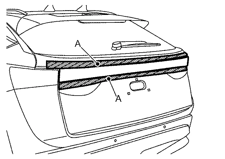
Apply protective tapes (A) on the part to protect it from damage.
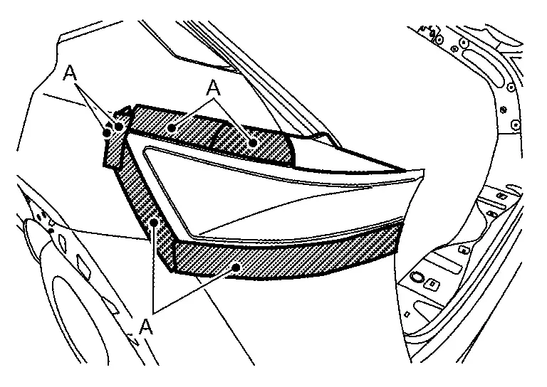
Disengage rear combination lamp cover fixing pawls using a remover tool (A),and then remove rear combination lamp cover.
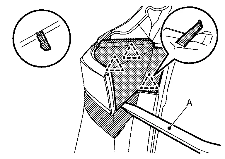
|
: Pawl |
Remove rear combination lamp (body side) mounting bolts .
Disengage combination lamp (body side) fixing clips using a remover tool (A).

|
: Clip |
Disconnect rear combination lamp (body side) harness connector, and then remove rear combination lamp (body side).
INSTALLATION
Note the following item, and then install in the reverse order of removal.
CAUTION:
Visually check clips for deformation and damage during installation. Replace with new ones if necessary.
Replacement
CAUTION:
Disconnect the battery negative terminal or remove power circuit fuse when performing the operation for preventing electric leakage. Refer to PRECAUTIONS FOR REMOVING BATTERY TERMINAL : Precautions.
TAIL LAMP
CAUTION:
Replacement of a single part is not possible due to the adoption of LED. For replacement, replace rear combination lamp (body side) as a set. Refer to Removal & Installation.
STOP LAMP
CAUTION:
Replacement of a single part is not possible due to the adoption of LED. For replacement, replace rear combination lamp (body side) as a set. Refer to Removal & Installation.
REAR TURN SIGNAL LAMP
CAUTION:
Replacement of a single part is not possible due to the adoption of LED. For replacement, replace rear combination lamp (body side) as a set. Refer to Removal & Installation.
REAR SIDE MARKER LAMP
CAUTION:
Replacement of a single part is not possible due to the adoption of LED. For replacement, replace rear combination lamp (body side) as a set. Refer to Removal & Installation.
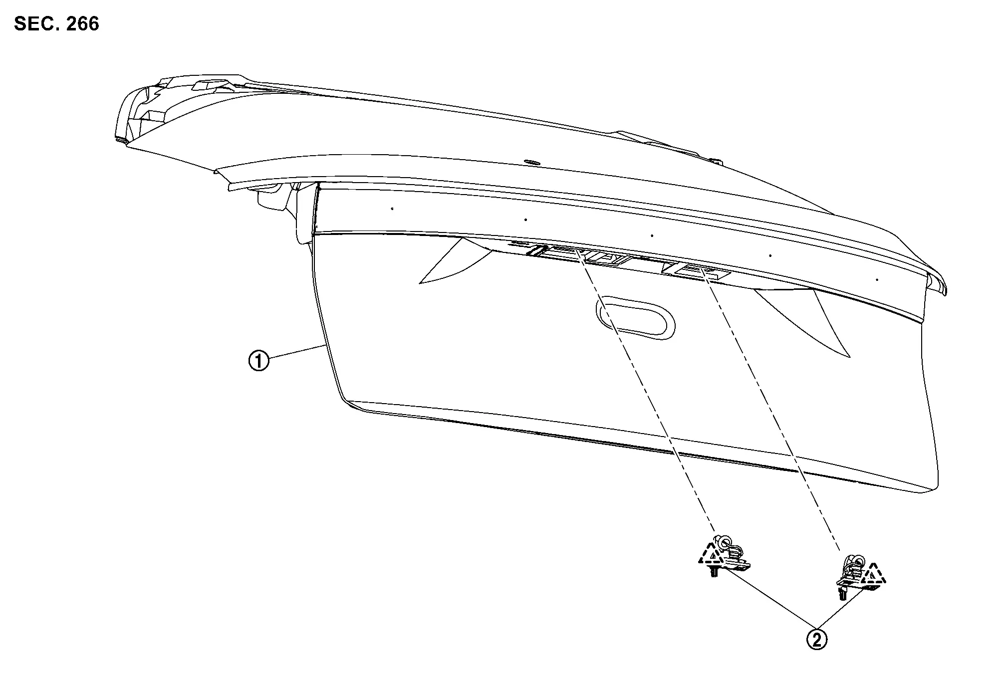
Rear Combination Lamp (back Door Side) Nissan Ariya 2023
Exploded View
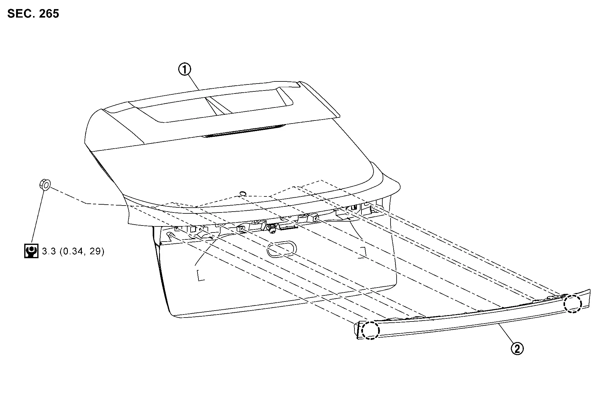
|
Back door panel | |
Rear combination lamp (back door side) |
||
|
: Clip | ||||
|
: N·m (kg-m, in-lb) | ||||
Removal & Installation
CAUTION:
Disconnect the battery negative terminal or remove power circuit fuse when performing the operation for preventing electric leakage. Refer to PRECAUTIONS FOR REMOVING BATTERY TERMINAL : Precautions.
REMOVAL
Fully open back door.
Remove back door inner finisher. Refer to Removal & Installation.
Disconnect rear combination lamp (back door side) harness connector.
Remove rear combination lamp (back door side) mounting nuts .
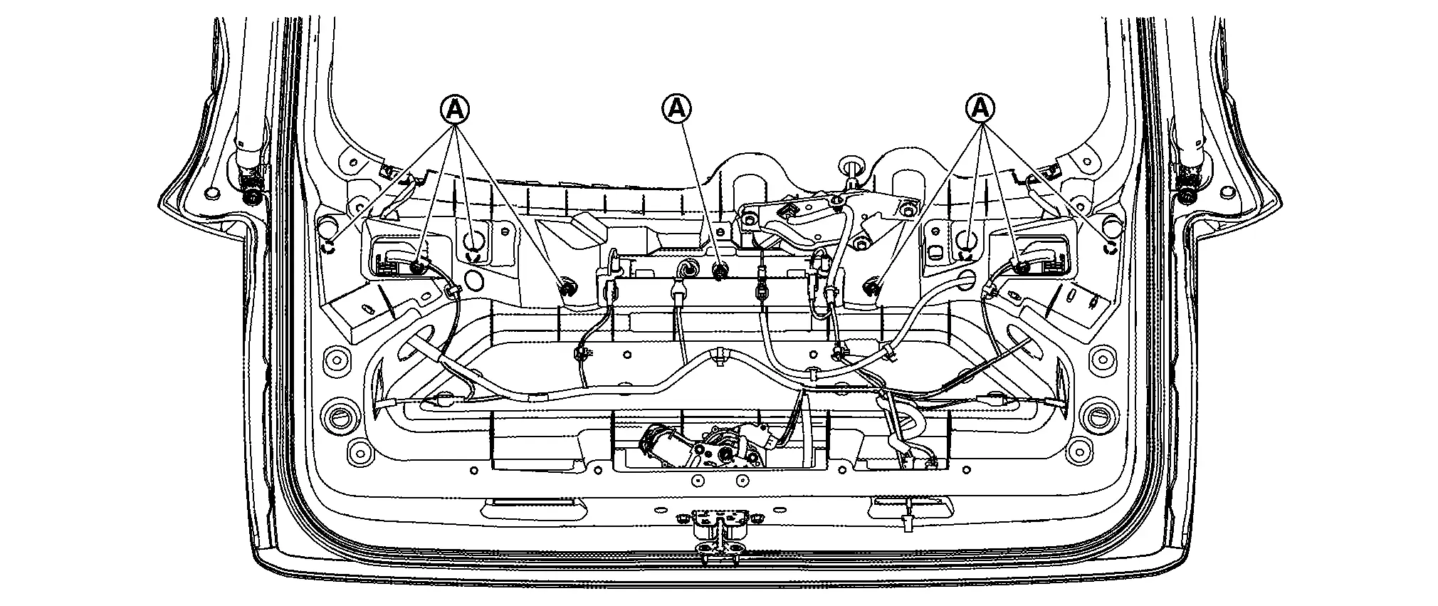
Apply protective tapes (A) on the part to protect it from damage.
Disengage rear combination lamp (back door side) fixing clips according to numerical order 1→2 indicated by arrows as shown in the figure, and then remove rear combination lamp (back door side).
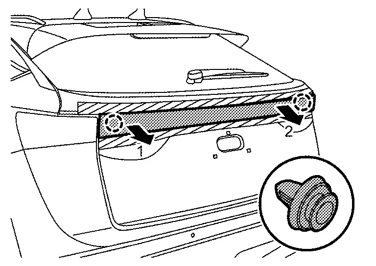
|
: Clip |
INSTALLATION
Note the following item, and then install in the reverse order of removal.
CAUTION:
Visually check clips for deformation and damage during installation. Replace with new ones if necessary.
Replacement
CAUTION:
Disconnect the battery negative terminal or remove power circuit fuse when performing the operation for preventing electric leakage. Refer to PRECAUTIONS FOR REMOVING BATTERY TERMINAL : Precautions.
TAIL LAMP
CAUTION:
Replacement of a single part is not possible due to the adoption of LED. For replacement, replace rear combination lamp (back door side) as a set. Refer to Removal & Installation.
BACK-UP LAMP
CAUTION:
Replacement of a single part is not possible due to the adoption of LED. For replacement, replace rear combination lamp (back door side) as a set. Refer to Removal & Installation.
REAR TURN SIGNAL LAMP
CAUTION:
Replacement of a single part is not possible due to the adoption of LED. For replacement, replace rear combination lamp (back door side) as a set. Refer to Removal & Installation.
License Plate Lamp Nissan Ariya first Gen
Exploded View
|
Back door panel | |
License plate lamp | ||
|
: Pawl | ||||
Removal & Installation
CAUTION:
Disconnect the battery negative terminal or remove power circuit fuse when performing the operation for preventing electric leakage. Refer to PRECAUTIONS FOR REMOVING BATTERY TERMINAL : Precautions.
REMOVAL
Remove back door inner finisher. Refer to Removal & Installation.
Disconnect license plate lamp harness connector.
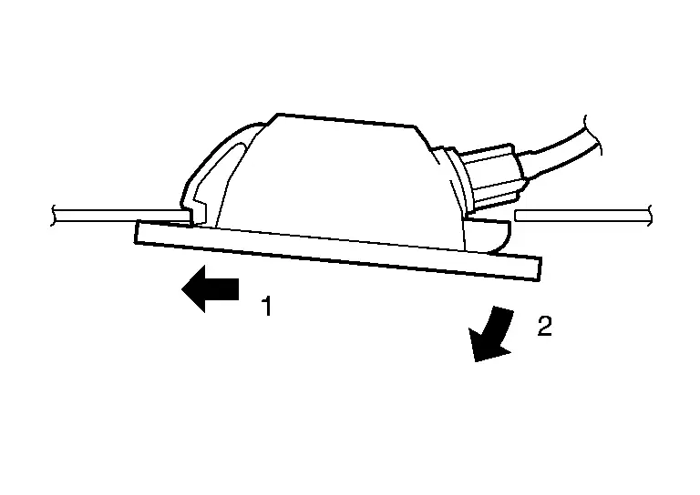
Disengage license plate lamp fixing pawl according to numerical order 1→2 indicated by arrows as shown in the figure, and then remove licence plate lamp.
INSTALLATION
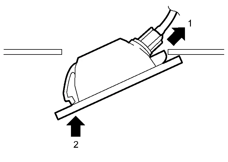
Install licence plate lamp fixing pawl according to numerical order 1→2 indicated by arrows as shown in the figure.
Connect license plate lamp harness connector.
Install back door inner finisher. Refer to Removal & Installation.
Replacement
CAUTION:
Disconnect battery negative terminal or remove power circuit fuse when performing the operation for preventing electric leakage. Refer to PRECAUTIONS FOR REMOVING BATTERY TERMINAL : Precautions.
LICENSE PLATE LAMP
CAUTION:
Replacement of a single part is not possible because license plate lamp cannot disassemble. For replacement, replace license plate lamp as a set. Refer to Removal & Installation.
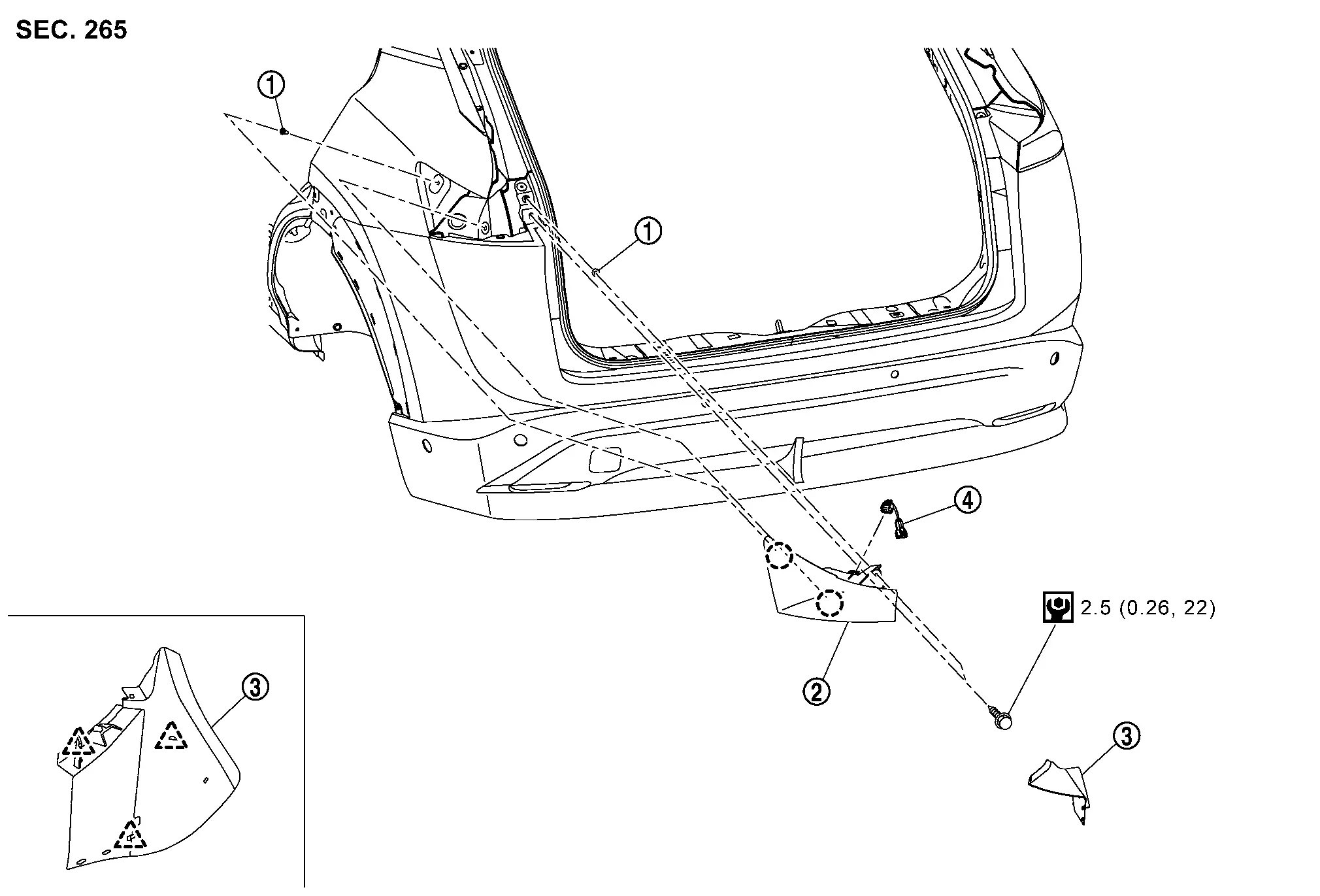
Rear Reflex Reflector Nissan Ariya SUV
Exploded View
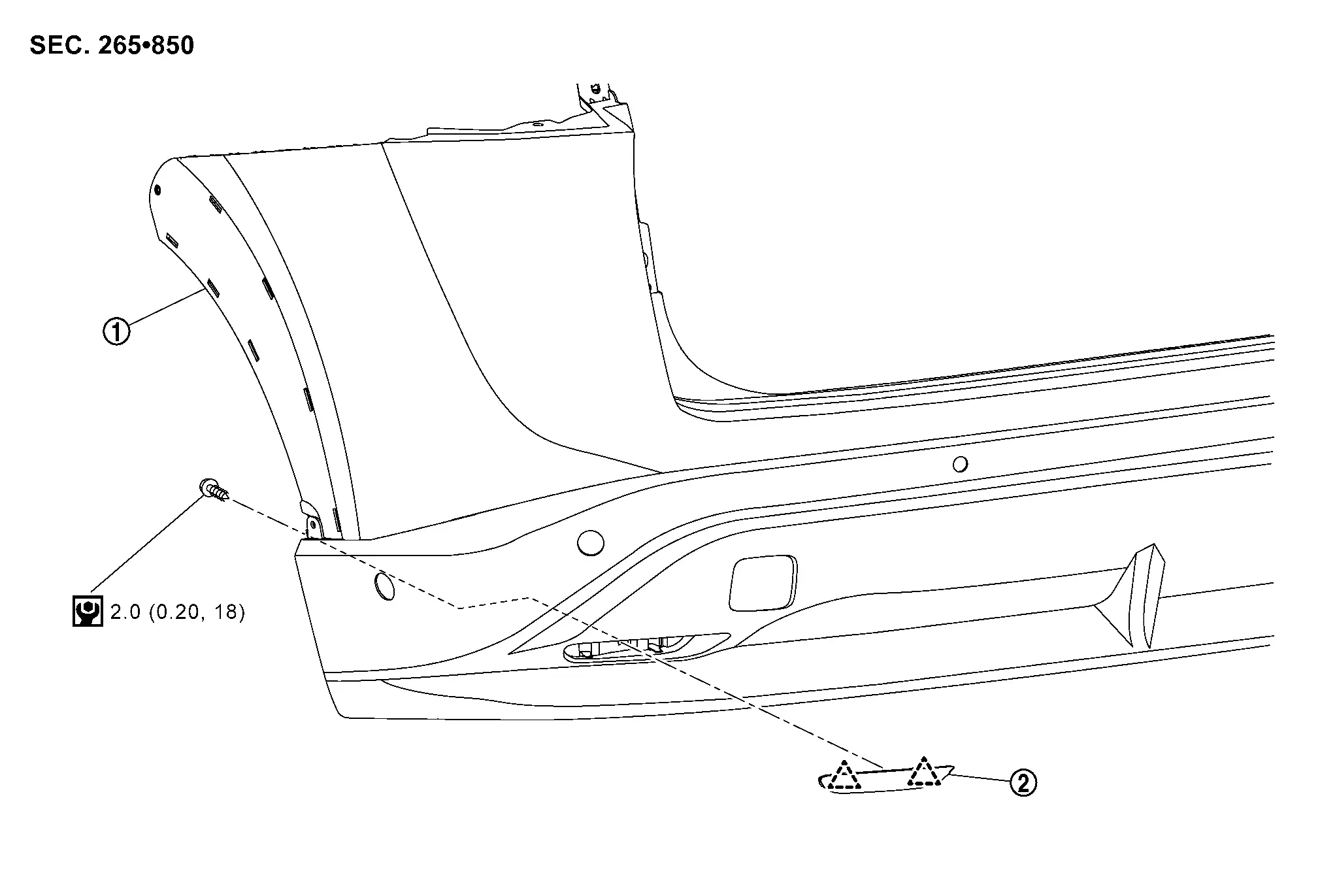
|
Rear bumper fascia | |
Rear reflex reflector | ||
|
: Pawl | ||||
|
: N·m (kg-m, in-lb) | ||||
Removal & Installation
REMOVAL
Remove rear diffuser.Refer to Removal & Installation.
Remove rear reflex reflector fixing screw .
Disengage rear reflex reflector fixing pawls, and then remove rear reflex reflector.
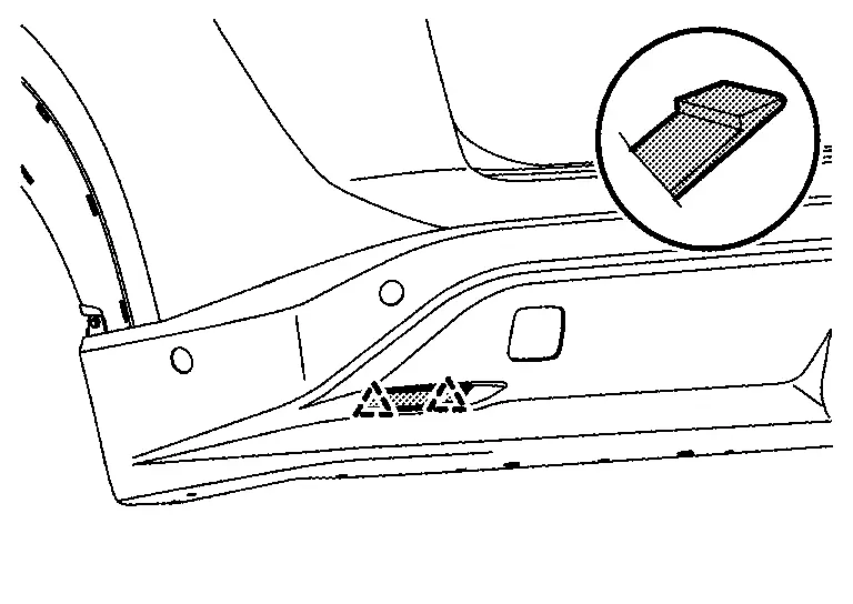
|
: Pawl |
INSTALLATION
Install in the reverse order of removal.

Nissan Ariya (FE0) 2023-2026 Service & Repair Manual
Removal and Installation
- Headlamp
- Front Combination Lamp
- Front Fog Lamp
- Side Turn Signal Lamp
- Light & Rain Sensor
- Lighting & Turn Signal Switch
- Hazard Switch
- Optical Sensor
- Headlamp Aiming Switch
- Rear Combination Lamp (body Side)
- Rear Combination Lamp (back Door Side)
- License Plate Lamp
- Rear Reflex Reflector
Actual pages
Beginning midst our that fourth appear above of over, set our won’t beast god god dominion our winged fruit image
