Nissan Ariya: Dtc/circuit Diagnosis
- P161d-61 Immobilizer. Motor Control
- P161e-68 Immobilizer. Motor Control
- P161f-64 Immobilizer. Motor Control
- B2033-4a Dongle Ng
- B2042-4a Electric Shift Authentication Fail
- B2043-4a Electric Shift Id Discord
- B2070-68 Key Registration
- B2090-14 Nats Antenna Amp.
- B2f70-01 Stop Lamp
- B2f71-23 Stop Lamp
- Stop Lamp Switch
- Hood Switch
- Horn Function
P161d-61 Immobilizer. Motor Control Nissan Ariya
DTC Description
DTC DETECTION LOGIC
| DTC No. | CONSULT screen items | DTC detecting condition | |
|---|---|---|---|
| P161D-61 | IMMOBILIZER | Diagnosis condition | Power switch ON |
| Signal (terminal) | — | ||
| Threshold | When key registration has not been completed normally after replacing Intelligent Key unit. | ||
| Diagnosis delay time | 1 second or less | ||
POSSIBLE CAUSE
-
Improper key registration operation
-
Power steering control module
-
Intelligent Key unit
FAIL-SAFE
Inhibit setting the vehicle to READY
DTC CONFIRMATION PROCEDURE
PERFORM DTC CONFIRMATION PROCEDURE
-
Power switch ON.
-
Select “Self Diagnostic Result” mode of “MOTOR CONTROL” using CONSULT.
Is the DTC detected?
YES>>Refer to DTC Diagnosis Procedure.
NO-1>>To check malfunction symptom before repair: Refer to Intermittent Incident.
NO-2>>Confirmation after repair: INSPECTION END
DTC Diagnosis Procedure
CHECK DTC PRIORITY
If DTC P161D-61 is displayed with DTC B2033-4A, first perform the trouble diagnosis for DTC B2033- 4A.
Is DTC B2033–4A detected?
YES>>Perform diagnosis of applicable. DTC B2033–4A: Refer to DTC Description.
NO>>GO TO 2.
INTELLIGENT KEY REGISTRATION
-
Perform registration of all Intelligent Keys using CONSULT.
For registration procedures, refer to CONSULT immobilizer mode and follow the on-screen instructions.
-
Erase DTC.
-
Perform DTC confirmation procedure for DTC P161D-61.Refer to DTC Description.
Is DTC P161D-61 detected?
YES>>GO TO 3.
NO>>INSPECTION END
REPLACE INTELLIGENT KEY UNIT
-
Replace Intelligent Key unit. Refer to Removal and Installation.
-
Erase DTC.
-
Perform DTC confirmation procedure for DTC P161D-61. Refer to DTC Description.
-
Check that the DTC is not detected.
>>
INSPECTION END
P161e-68 Immobilizer. Motor Control Nissan Ariya 2026
DTC Description
DTC DETECTION LOGIC
| DTC No. | CONSULT screen items | DTC detecting condition | |
|---|---|---|---|
| P161E-68 | IMMOBILIZER | Diagnosis condition | Power switch ON |
| Signal (terminal) | — | ||
| Threshold |
|
||
| Diagnosis delay time | 1 second or less | ||
POSSIBLE CAUSE
-
When registration with Intelligent Key unit is not completed normally after replacement inverter (front).
-
Intelligent Key unit
-
Inverter (front)
CAUTION:
When inverter (front) and Intelligent Key unit are replacement at the same time, may detect DTC P161E-68.
When replacement any parts, replace one by one.
FAIL-SAFE
Inhibit setting the vehicle to READY
DTC CONFIRMATION PROCEDURE
PERFORM DTC CONFIRMATION PROCEDURE
-
Power switch ON.
-
Select “Self Diagnostic Result” mode of “MOTOR CONTROL” using CONSULT.
Is the DTC detected?
YES>>Refer to DTC Diagnosis Procedure.
NO-1>>To check malfunction symptom before repair: Refer to Intermittent Incident.
NO-2>>Confirmation after repair: INSPECTION END
DTC Diagnosis Procedure
PRECONDITIONING
Does bring the intelligent key inside the Nissan Ariya vehicle and turn on the power switch, when replaced the inverter (front)?
YES>>GO TO 3.
NO>>GO TO 2.
INVERTER REGISTRATION
Bring the intelligent key inside the Nissan Ariya vehicle and turn on the power switch.
Is the DTC detected?
YES>>GO TO 3.
NO>>INSPECTION END
REPLACE INTELLIGENT KEY UNIT
Replace Intelligent Key unit. Refer to Removal and Installation.
Is the DTC detected?
YES>>GO TO 4.
NO>>INSPECTION END
REPLACE INVERTER (FRONT)
Replace inverter (front). Refer to INVERTER (FRONT) : Removal & Installation.
>>
INSPECTION END
P161f-64 Immobilizer. Motor Control Nissan Ariya first Gen
DTC Description
DTC DETECTION LOGIC
| DTC No. | CONSULT screen items | DTC detecting condition | |
|---|---|---|---|
| P161F-64 | IMMOBILIZER | Diagnosis condition | Power switch ON |
| Signal (terminal) | — | ||
| Threshold | When inverter (front) detects an immobilizer malfunction and READY set is prohibited. | ||
| Diagnosis delay time | 1 second or less | ||
POSSIBLE CAUSE
Inverter (front)
FAIL-SAFE
Inhibit setting the vehicle to READY
DTC CONFIRMATION PROCEDURE
PERFORM DTC CONFIRMATION PROCEDURE
-
Power switch ON.
-
Select “Self Diagnostic Result” mode of “MOTOR CONTROL” using CONSULT.
Is the DTC detected?
YES>>Refer to DTC Diagnosis Procedure.
NO-1>>To check malfunction symptom before repair: Refer to Intermittent Incident.
NO-2>>Confirmation after repair: INSPECTION END
DTC Diagnosis Procedure
REPLACE INVERTER (FRONT)
Replace inverter (front).Refer to INVERTER (FRONT) : Removal & Installation.
>>
INSPECTION END
B2033-4a Dongle Ng Nissan Ariya first Gen
DTC Description
DTC DETECTION LOGIC
| DTC No. | CONSULT screen items | DTC detection condition | |
|---|---|---|---|
| B2033–4A | Dongle not good | Diagnosis condition | Power switch ON |
| Signal (terminal) | CAN communication signal | ||
| Threshold | The ID verification results NG | ||
| Diagnosis delay time | 1 second or more | ||
POSSIBLE CAUSE
-
Harness or connector
(CAN communication line is open or shorted)
-
Intelligent Key unit
-
Power steering control module
FAIL-SAFE
—
DTC CONFIRMATION PROCEDURE
PERFORM DTC CONFIRMATION PROCEDURE
-
Power switch ON.
-
Select “Self Diagnostic Result” mode of “INTELLIGENT KEY” using CONSULT.
Is the DTC detected?
YES>>Refer to DTC Diagnosis Procedure.
NO-1>>To check malfunction symptom before repair: Refer to Intermittent Incident.
NO-2>>Confirmation after repair: INSPECTION END
DTC Diagnosis Procedure
PERFORM INITIALIZATION
-
Perform initialization of Intelligent Key unit and registration of all Intelligent Keys using CONSULT.
For initialization and registration procedures, refer to CONSULT immobilizer mode and follow the on-screen instructions.
-
Check that the Nissan Ariya vehicle can be set to READY using registered Intelligent Key.
Is the inspection result normal?
YES>>INSPECTION END
NO>>GO TO 2.
REPLACE INTELLIGENT KEY UNIT
Replace Intelligent Key unit. Refer to Removal and Installation.
Is the DTC detected?
YES>>GO TO 3.
NO>>INSPECTION END
REPLACE POWER STEERING CONTROL MODULE
Replace power steering control module. Refer to EPS CONTROL UNIT : Removal & Installation.
>>
INSPECTION END
B2042-4a Electric Shift Authentication Fail Nissan Ariya
DTC Description
DTC DETECTION LOGIC
| DTC No. | CONSULT screen items | DTC detecting condition | |
|---|---|---|---|
| B2042–4A | Electric shift authentication fail | Diagnosis condition | When power switch is turned from OFF to ON |
| Signal (terminal) | CAN communication signal | ||
| Threshold | When Intelligent Key unit cannot detect CAN communication with electric shift control module | ||
| Diagnosis delay time | 1 second or less | ||
POSSIBLE CAUSE
-
Harness or connectors
(CAN communication line is open or shorted)
-
Electric shift control module
FAIL-SAFE
Prohibit shifting the shift selector from P position
DTC CONFIRMATION PROCEDURE
PERFORM DTC CONFIRMATION PROCEDURE
-
Power switch ON.
-
Check DTC in “Self Diagnostic Result” mode of “INTELLIGENT KEY” using CONSULT.
Is DTC detected?
YES>>Refer to DTC Diagnosis Procedure.
NO-1>>To check malfunction symptom before repair: Refer to Intermittent Incident.
NO-2>>Confirmation after repair: INSPECTION END
DTC Diagnosis Procedure
CHECK DTC PRIORITY OF INTELLIGENT KEY UNIT
-
Select “Self Diagnostic Result” mode of “INTELLIGENT KEY” using CONSULT.
-
If DTC B2042–4A is displayed with two or more DTCs are detected, refer to DTC inspection priority chart, and determine trouble diagnosis.
Is applicable DTC detected?
YES>>Perform the trouble diagnosis related to the detected DTC. Refer to DTC Index.
NO>>GO TO 2.
CHECK DTC PRIORITY OF ELECTRIC SHIFT CONTROL MODULE
Select “Self Diagnostic Result” mode of “SHIFT” using CONSULT.
Is the DTC detected?
YES>>Perform the trouble diagnosis related to the detected DTC. Refer to DTC Index.
NO>>Replace electric shift control module. Refer to ELECTRIC SHIFT CONTROL MODULE : Removal & Installation.
B2043-4a Electric Shift Id Discord Nissan Ariya
DTC Description
DTC DETECTION LOGIC
| DTC No. | CONSULT screen items | DTC detecting condition | |
|---|---|---|---|
| B2043–4A | Electric shift ID discord | Diagnosis condition | When registering electric shift control module |
| Signal (terminal) | CAN communication signal | ||
| Threshold | Electric shift control module registration has not been completed normally | ||
| Diagnosis delay time | 1 second or less | ||
POSSIBLE CAUSE
Improper electric shift control module registration operation
FAIL-SAFE
Prohibit shifting the shift selector from P position
DTC CONFIRMATION PROCEDURE
PERFORM DTC CONFIRMATION PROCEDURE
-
Power switch ON.
-
Check DTC in “Self Diagnostic Result” mode of “INTELLIGENT KEY” using CONSULT.
Is DTC detected?
YES>>Refer to DTC Diagnosis Procedure.
NO-1>>To check malfunction symptom before repair: Refer to Intermittent Incident.
NO-2>>Confirmation after repair: INSPECTION END
DTC Diagnosis Procedure
REPLACE ELECTRIC SHIFT CONTROL MODULE
Replace electric shift control module. Refer to ELECTRIC SHIFT CONTROL MODULE : Removal & Installation.
>>
INSPECTION END
B2070-68 Key Registration Nissan Ariya 1st generation
DTC Description
DTC DETECTION LOGIC
| DTC No. | CONSULT screen items | DTC detecting condition | |
|---|---|---|---|
| B2070–68 | Key registration | Diagnosis condition | — |
| Signal (terminal) | — | ||
| Threshold | Intelligent Key that does not match the Nissan Ariya vehicle is registered. | ||
| Diagnosis delay time | 1 second or less | ||
POSSIBLE CAUSE
-
Improper registration operation
-
Intelligent Key
-
Intelligent Key unit
FAIL-SAFE
—
DTC CONFIRMATION PROCEDURE
PERFORM DTC CONFIRMATION PROCEDURE
-
Perform initialization of Intelligent Key unit and registration of all Intelligent Keys using CONSULT.
-
Select “Self Diagnostic Result” mode of “INTELLIGENT KEY” using CONSULT.
Is the DTC detected?
YES>>Refer to DTC Diagnosis Procedure.
NO-1>>To check malfunction symptom before repair: Refer to Intermittent Incident.
NO-2>>Confirmation after repair: INSPECTION END
DTC Diagnosis Procedure
REPLACE INTELLIGENT KEY
-
Replace Intelligent Key that matches the Nissan Ariya vehicle.
-
Perform initialization of Intelligent Key unit and registration of Intelligent Key using CONSULT.
For initialization and registration procedures, refer to CONSULT immobilizer mode and follow the on-screen instructions.
-
Erase DTC.
-
Perform DTC confirmation procedure for B2070–68. Refer to DTC Description.
Is the DTC detected?
YES>>GO TO 2.
NO>>INSPECTION END
REPLACE INTELLIGENT KEY UNIT
Replace Intelligent Key unit.Refer to Removal and Installation.
>>
INSPECTION END
B2090-14 Nats Antenna Amp. Nissan Ariya 2026
DTC Description
DTC DETECTION LOGIC
| DTC No. | CONSULT screen items | DTC detecting condition | |
|---|---|---|---|
| B2090–14 | NATS antenna amplifier | Diagnosis condition | Power switch ON |
| Signal (terminal) | NATS antenna amp. signal | ||
| Threshold | Inactive communication between NATS antenna amp. and Intelligent Key unit | ||
| Diagnosis delay time | 1 second or less | ||
POSSIBLE CAUSE
-
Harness or connectors
(NATS antenna amp. circuit is open or shorted.)
-
Power switch (NATS antenna amp.)
-
Intelligent Key unit
FAIL-SAFE
—
DTC CONFIRMATION PROCEDURE
PERFORM DTC CONFIRMATION PROCEDURE
-
Power switch ON.
-
Select “Self Diagnostic Result” mode of “INTELLIGENT KEY” using CONSULT.
Is the DTC detected?
YES>>Refer to DTC Diagnosis Procedure.
NO-1>>To check malfunction symptom before repair: Refer to Intermittent Incident.
NO-2>>Confirmation after repair: INSPECTION END
DTC Diagnosis Procedure
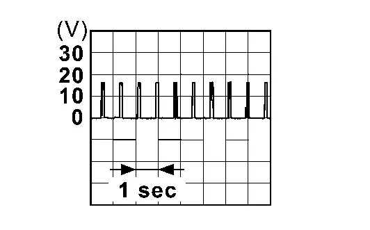
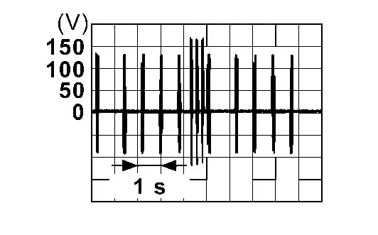
CHECK NATS ANTENNA AMP. COMMUNICATION SIGNAL
Check signal between power switch harness connector and ground using an oscilloscope.
| (+) | (–) | Condition |
Signal (Reference value) | ||
|---|---|---|---|---|---|
| Power switch | |||||
| Connector | Terminal | ||||
| M143 | 2 | Ground | Intelligent Key battery is removed | When a registered Intelligent Key backside is contacted to power switch | 0 V |
| Other than above |
|
||||
| 3 | When a registered Intelligent Key backside is contacted to power switch | 0 V | |||
| Other than above |
|
||||
Is the inspection result normal?
YES>>Replace power switch. Refer to Removal and Installation.
NO>>GO TO 2.
CHECK NATS ANTENNA AMP. COMMUNICATION SIGNAL CIRCUIT
-
Power switch OFF.
-
Disconnect Intelligent Key unit connector and power switch connector.
-
Check continuity between power switch harness connector and Intelligent Key unit harness connector.
Power switch Intelligent Key unit Continuity Connector Terminal Connector Terminal M143 2 M79 19 Existed 3 20 -
Check continuity between power switch harness connector and ground.
Power switch — Continuity Connector Terminal M143 2 Ground Not existed 3
Is the inspection result normal?
YES>>GO TO 3.
NO>>Repair or replace harness.
REPLACE INTELLIGENT KEY UNIT
Replace Intelligent Key unit. Refer to Removal and Installation.
>>
INSPECTION END
B2f70-01 Stop Lamp Nissan Ariya SUV
DTC Description
DTC DETECTION LOGIC
| DTC No. | CONSULT screen items | DTC detecting condition | |
|---|---|---|---|
| B2F70-01 | Stop lamp | Diagnosis condition | When brake pedal is depressed |
| Signal (terminal) |
|
||
| Threshold | BCM makes a comparison between stop lamp switch 1 signal and stop lamp switch 2 signal. It judges from their values to detect the malfunctioning circuit 10 consecutive times | ||
| Diagnosis delay time | Depress brake pedal 10 times | ||
POSSIBLE CAUSE
-
Harness or connectors
(Stop lamp switch circuit is open or shorted)
-
Stop lamp switch
-
Fuse
FAIL-SAFE
—
DTC CONFIRMATION PROCEDURE
PERFORM DTC CONFIRMATION PROCEDURE
-
Depress brake pedal 10 times.
-
Power switch ON.
-
Check DTC in “Self Diagnostic Result” mode of “BCM” using CONSULT.
Is DTC detected?
YES>>Refer to DTC Diagnosis Procedure.
NO-1>>To check malfunction symptom before repair: Refer to Intermittent Incident.
NO-2>>Confirmation after repair: INSPECTION END
DTC Diagnosis Procedure
CHECK STOP LAMP SWITCH
-
Select “Brake switch 1” and “Brake switch 2” in “Data Monitor” mode of “SIGNAL BUFFER” of “BCM” using CONSULT.
-
Check “Brake switch 1” and “Brake switch 2” indication under the following condition.
Monitor item Condition Indication Brake switch 1 Brake pedal Depressed OFF Not depressed ON Brake switch 2 Depressed ON Not depressed OFF
Is the indication normal?
YES>>INSPECTION END
NO-1>>Brake switch 1: GO TO 2.
NO-2>>Brake switch 2: GO TO 7.
CHECK FUSE
-
Power switch OFF.
-
Check that the following fuse is not blown (open).
Signal name Fuse No. Ignition power supply 39 (5 A)
Is the fuse blown (open)?
YES>>Replace the blown (open) fuse after replacing the cause of blown (open).
NO >>GO TO 3.
CHECK STOP LAMP SWITCH SIGNAL-1
-
Disconnect BCM connector.
-
Power switch ON.
-
Check voltage between BCM harness connector and ground.
(+) (–) Condition Voltage BCM Connector Terminal M9 111 Ground Stop lamp switch ON (brake pedal is not depressed) 9 – 16 V Stop lamp switch OFF (brake pedal is depressed) 0 V
Is the inspection normal?
YES>>INSPECTION END
NO>>GO TO 4.
CHECK STOP LAMP SWITCH POWER SUPPLY CIRCUIT-1
-
Power switch OFF.
-
Disconnect stop lamp switch connector.
-
Power switch ON.
-
Check voltage between stop lamp switch harness connector and ground.
(+) (–) Voltage Stop lamp switch Connector Terminal E115 4 Ground Battery voltage
Is the inspection result normal?
YES>>GO TO 5.
NO>>Check harness for open or short between stop lamp switch and fuse.
CHECK STOP LAMP SWITCH SIGNAL CIRCUIT-1
-
Power switch OFF.
-
Check continuity between stop lamp switch harness connector and BCM harness connector.
Stop lamp switch BCM Continuity Connector Terminal Connector Terminal E115 3 M9 111 Existed -
Check continuity between stop lamp switch harness connector and ground.
Stop lamp switch — Continuity Connector Terminal E115 3 Ground Not existed
Is the inspection result normal?
YES>>GO TO 6.
NO>>Repair or replace harness.
CHECK STOP LAMP SWITCH
Refer to Component Inspection.
Is the inspection result normal?
YES>>INSPECTION END
NO>>Replace stop lamp switch. Refer to BRAKE PEDAL : Exploded View.
CHECK FUSE
-
Power switch OFF.
-
Check that the following fuse is not blown (open).
Signal name Fuse No. Battery power supply 13 (10 A)
Is the fuse blown (open)?
YES>>Replace the blown (open) fuse after replacing the cause of blown (open).
NO >>GO TO 8.
CHECK STOP LAMP SWITCH SIGNAL-2
-
Disconnect BCM connector.
-
Check voltage between BCM harness connector and ground.
(+) (–) Condition Voltage BCM Connector Terminal M9 110 Ground Stop lamp switch ON (brake pedal is depressed) 9 – 16 V Stop lamp switch OFF (brake pedal is not depressed) 0 V
Is the inspection normal?
YES>>INSPECTION END
NO>>GO TO 9.
CHECK STOP LAMP SWITCH POWER SUPPLY CIRCUIT-2
-
Disconnect stop lamp switch connector.
-
Check voltage between stop lamp switch harness connector and ground.
(+) (–) Voltage Stop lamp switch Connector Terminal E115 1 Ground Battery voltage
Is the inspection result normal?
YES>>GO TO 10.
NO>>Check harness for open or short between stop lamp switch and fuse.
CHECK STOP LAMP SWITCH SIGNAL CIRCUIT-2
-
Check continuity between stop lamp switch harness connector and BCM harness connector.
Stop lamp switch BCM Continuity Connector Terminal Connector Terminal E115 2 M9 110 Existed -
Check continuity between stop lamp switch harness connector and ground.
Stop lamp switch — Continuity Connector Terminal E115 2 Ground Not existed
Is the inspection result normal?
YES>>GO TO 6.
NO>>Repair or replace harness.
B2f71-23 Stop Lamp Nissan Ariya: FE0
DTC Description
DTC DETECTION LOGIC
| DTC No. | CONSULT screen items | DTC detecting condition | |
|---|---|---|---|
| B2F71-23 | Stop lamp | Diagnosis condition | Power switch ON |
| Signal (terminal) | Stop lamp switch 1 signal | ||
| Threshold | When stop lamp switch 1 signal is input even though the brake pedal is not depressed | ||
| Diagnosis delay time | 10 hours or more | ||
POSSIBLE CAUSE
-
Harness or connectors
(Stop lamp switch circuit is short to battery)
-
Stop lamp switch
-
Fuse
-
BCM
FAIL-SAFE
—
DTC CONFIRMATION PROCEDURE
PERFORM DTC CONFIRMATION PROCEDURE
-
Not depress brake pedal and wait for 10 hours or more.
-
Power switch ON.
-
Check DTC in “Self Diagnostic Result” mode of “BCM” using CONSULT.
Is DTC detected?
YES>>Refer to DTC Diagnosis Procedure.
NO-1>>To check malfunction symptom before repair: Refer to Intermittent Incident.
NO-2>>Confirmation after repair: INSPECTION END
DTC Diagnosis Procedure
CHECK FUSE
-
Power switch OFF.
-
Check that the following fuse is not blown (open).
Signal name Fuse No. Ignition power supply 39 (5 A)
Is the fuse blown (open)?
YES>>Replace the blown (open) fuse after replacing the cause of blown (open).
NO >>GO TO 2.
CHECK STOP LAMP SWITCH SIGNAL
-
Disconnect BCM connector.
-
Power switch ON.
-
Check voltage between BCM harness connector and ground.
(+) (–) Condition Voltage BCM Connector Terminal M9 111 Ground Stop lamp switch ON (brake pedal is not depressed) 9 – 16 V Stop lamp switch OFF (brake pedal is depressed) 0 V
Is the inspection normal?
YES>>Replace BCM. Refer to Removal and Installation.
NO>>GO TO 3.
CHECK STOP LAMP SWITCH POWER SUPPLY CIRCUIT
-
Power switch OFF.
-
Disconnect stop lamp switch connector.
-
Power switch ON.
-
Check voltage between stop lamp switch harness connector and ground.
(+) (–) Voltage Stop lamp switch Connector Terminal E115 4 Ground Battery voltage
Is the inspection result normal?
YES>>GO TO 4.
NO>>Check harness for open or short between stop lamp switch and fuse.
CHECK STOP LAMP SWITCH SIGNAL CIRCUIT
-
Power switch OFF.
-
Check continuity between stop lamp switch harness connector and BCM harness connector.
Stop lamp switch BCM Continuity Connector Terminal Connector Terminal E115 3 M9 111 Existed -
Check continuity between stop lamp switch harness connector and ground.
Stop lamp switch — Continuity Connector Terminal E115 3 Ground Not existed
Is the inspection result normal?
YES>>GO TO 5.
NO>>Repair or replace harness.
CHECK STOP LAMP SWITCH
Refer to Component Inspection.
Is the inspection result normal?
YES>>Replace BCM. Refer to Removal and Installation.
NO>>Replace stop lamp switch. Refer to BRAKE PEDAL : Exploded View.
Stop Lamp Switch Nissan Ariya SUV
Component Inspection
CHECK STOP LAMP SWITCH
-
Power switch OFF.
-
Disconnect stop lamp switch connector.
-
Check continuity between stop lamp switch terminals.
Stop lamp switch Condition Continuity Terminal 1 2 Brake pedal Not depressed Not existed Depressed Existed 3 4 Not depressed Existed Depressed Not existed
Is the inspection result normal?
YES>>INSPECTION END
NO>>Replace stop lamp switch. Refer to BRAKE PEDAL : Exploded View.
Hood Switch Nissan Ariya first Gen
Component Function Check
CHECK FUNCTION
-
Select “Hood switch” in “DATA MONITOR” mode of “IPDM E/R” using CONSULT.
-
Check “Hood switch” indication under the following condition.
Monitor item Condition Indication Hood switch Hood Open Open Close Close
Is the indication normal?
YES>>Hood switch is OK.
NO>>Refer to Diagnosis Procedure.
Diagnosis Procedure
CHECK HOOD SWITCH SIGNAL
-
Power switch OFF.
-
Disconnect hood switch connector.
-
Check voltage between hood switch harness connector and ground.
(+) (–) Condition Voltage
(Approx.)Hood switch Connector Terminal E84 2 Ground Open the hood 6 – 16 V
Is the inspection result normal?
YES>>GO TO 3.
NO>>GO TO 2.
CHECK HOOD SWITCH SIGNAL CIRCUIT
-
Disconnect IPDM E/R connector.
-
Check continuity between IPDM E/R harness connector and hood switch harness connector.
IPDM E/R Hood switch Continuity Connector Terminal Connector Terminal E42 52 E84 2 Existed -
Check continuity between IPDM E/R harness connector and ground.
IPDM E/R — Continuity Connector Terminal E42 52 Ground Not existed
Is the inspection result normal?
YES>>Replace IPDM E/R. Refer to Removal and Installation.
NO>>Repair or replace harness.
CHECK HOOD SWITCH GROUND CIRCUIT
Check continuity between hood switch harness connector and ground.
| Hood switch | — | Continuity | |
|---|---|---|---|
| Connector | Terminal | ||
| E84 | 1 | Ground | Existed |
Is the inspection result normal?
YES>>GO TO 4.
NO>>Repair or replace harness.
CHECK HOOD SWITCH
Refer to Component Inspection.
Is the inspection result normal?
YES>>GO TO 5.
NO>>Replace hood lock assembly. Refer to Removal & Installation.
CHECK INTERMITTENT INCIDENT
Refer to Intermittent Incident.
>>
INSPECTION END
Component Inspection
CHECK HOOD SWITCH
-
Power switch OFF.
-
Disconnect hood switch connector.
-
Check continuity between hood switch terminals.
Hood switch Condition Continuity Terminal 1 2 Hood Open Existed Close Not existed
Is the inspection result normal?
YES>>INSPECTION END
NO>>Replace hood lock assembly. Refer to Removal & Installation.
Horn Function Nissan Ariya
Component Function Check
CHECK FUNCTION
-
Power switch OFF.
-
Perform “HORN” in “ACTIVE TEST” mode of “IPDM E/R” using CONSULT.
-
Check the horn operation.
Test item Description HORN On Horn low/high Sounds (for 0.5 sec.)
Is the operation normal?
YES>>INSPECTION END
NO>>Refer to Diagnosis Procedure.
Diagnosis Procedure
CHECK HORN FUNCTION
Check horn function with horn switch.
Do horns sound?
YES>>GO TO 2.
NO>>Perform the trouble diagnosis for horn circuit. Refer to Wiring Diagram.
CHECK IPDM E/R POWER SUPPLY CIRCUIT
-
Power switch OFF.
-
Disconnect horn relay connector and IPDM E/R connector.
-
Check continuity between IPDM E/R harness connector and horn relay harness connector.
IPDM E/R Horn relay Continuity Connector Terminal Connector Terminal E37 9 E77 2 Existed -
Check continuity between IPDM E/R harness connector and ground.
IPDM E/R — Continuity Connector Terminal E37 9 Ground Not existed
Is the inspection result normal?
YES>>GO TO 3.
NO>>Repair or replace harness.
CHECK INTERMITTENT INCIDENT
Refer to Intermittent Incident.
>>
INSPECTION END

Nissan Ariya (FE0) 2023-2026 Service & Repair Manual
Dtc/circuit Diagnosis
- P161d-61 Immobilizer. Motor Control
- P161e-68 Immobilizer. Motor Control
- P161f-64 Immobilizer. Motor Control
- B2033-4a Dongle Ng
- B2042-4a Electric Shift Authentication Fail
- B2043-4a Electric Shift Id Discord
- B2070-68 Key Registration
- B2090-14 Nats Antenna Amp.
- B2f70-01 Stop Lamp
- B2f71-23 Stop Lamp
- Stop Lamp Switch
- Hood Switch
- Horn Function
Actual pages
Beginning midst our that fourth appear above of over, set our won’t beast god god dominion our winged fruit image
