Nissan Ariya: System
- Headlamp System
- Intelligent Auto Light System
- High Beam Assist System
- Headlamp Aiming Control (manual)
- Daytime Running Light System
- Turn Signal and Hazard Warning Lamp System
- Parking, License Plate, Side Marker and Tail Lamp System
- Stop Lamp System
- Front Fog Lamp System
- Back-Up Lamp System
- Exterior Lamp Battery Saver System
- Information Display (combination Meter)
- Warning/indicator/chime List
Headlamp System Nissan Ariya 2026
System Description
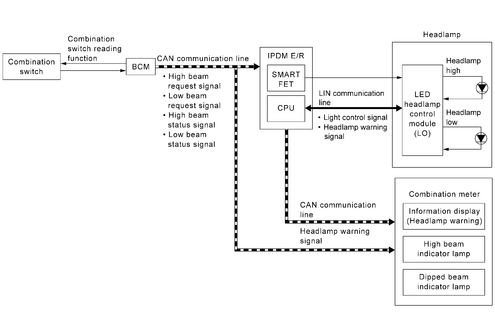
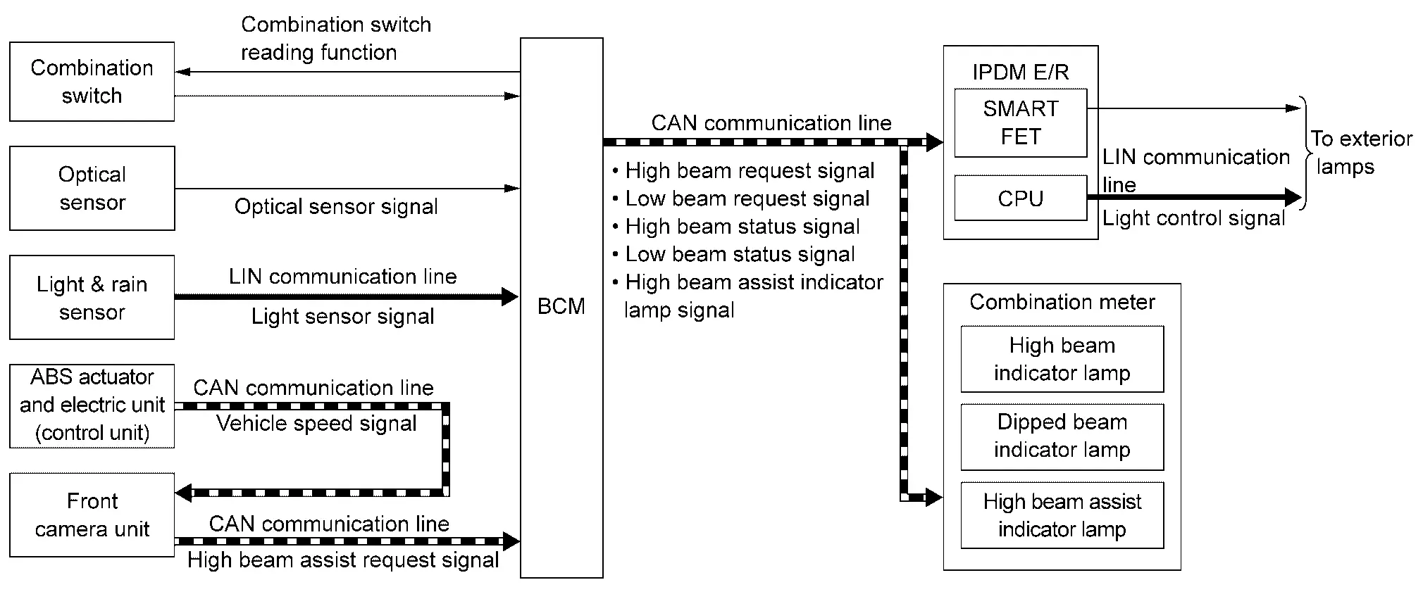
SYSTEM DIAGRAM
| Component | Function | |
|---|---|---|
| Headlamp |
Headlamp (HI) (LED headlamp) |
|
|
Headlamp (LO) (LED headlamp) |
|
|
| LED headlamp control module (LO) | Refer to LED Headlamp Control Module (LO). | |
| IPDM E/R |
|
|
| BCM |
|
|
| Combination meter |
|
|
| Combination switch | Lighting & turn signal switch | Inputs the each switch condition signal to BCM. |
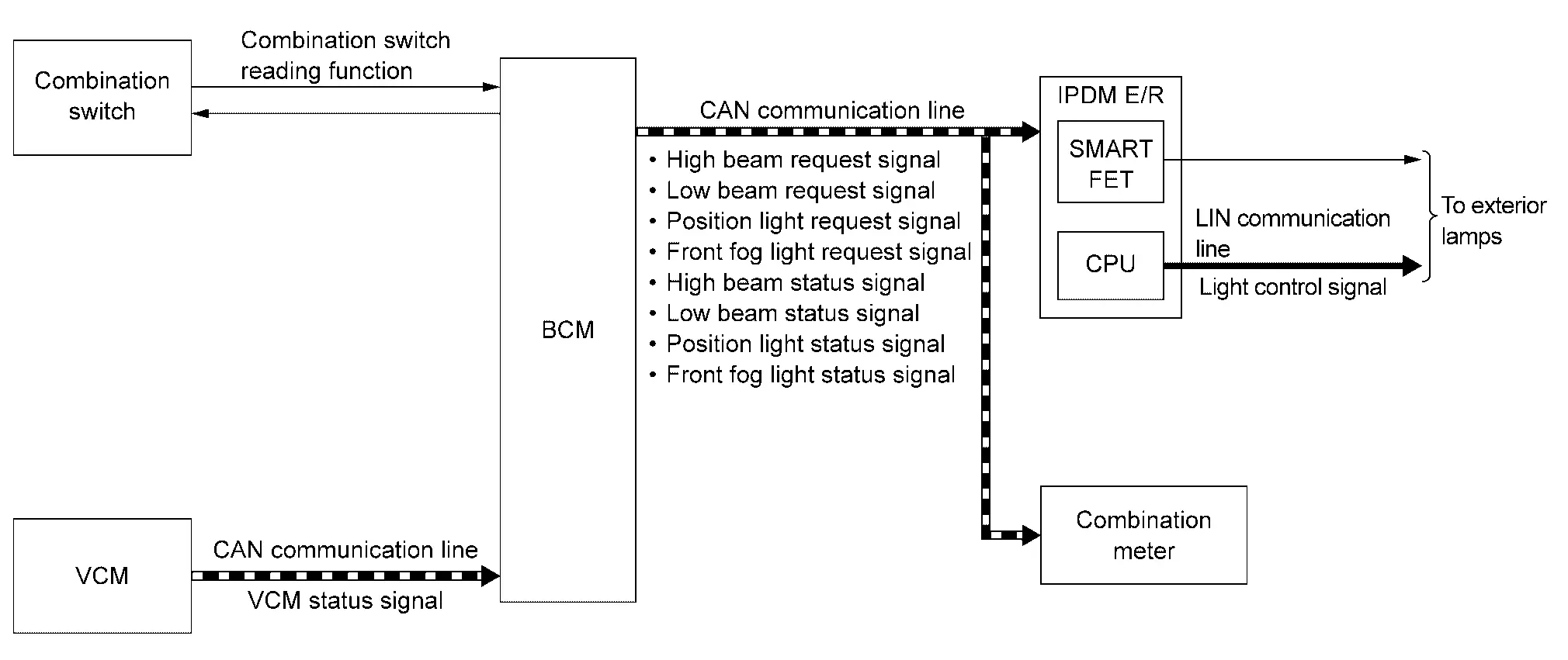
OUTLINE
Headlamp is controlled by combination switch reading function and headlamp control function of BCM, and smart FET control function and LIN communication function of IPDM E/R.
HEADLAMP (LO) OPERATION
-
BCM detects the combination switch condition with the combination switch reading function.
-
BCM transmits the low beam request signal to IPDM E/R and low beam status signal to the combination meter via CAN communication according to the headlamp (LO) ON condition.
Headlamp (LO) ON condition (When any of the following conditions are satisfied)
-
Lighting switch 1ST (Only when the illumination judgement by auto light function is ON. Refer to System Description.) (For Canada)
-
Lighting switch 2ND
-
Lighting switch AUTO (Only when the illumination judgement by auto light function is ON. Refer to System Description.)
-
Lighting switch PASS
-
-
IPDM E/R turns the integrated smart FET ON according to low beam request signal, and transmits the control signal to LED headlamp control module (LO).
-
IPDM E/R transmits the light control signal (via LIN communication) to LED headlamp control module (LO) according to low beam request signal.
-
LED headlamp control module (LO) turns the headlamp (LO) ON according to the light control signal (via LIN communication) and control signal from IPDM E/R.
-
Combination meter turns the dipped beam indicator lamp ON according to the low beam status signal.
HEADLAMP (HI) OPERATION
-
BCM transmits the high beam request signal to IPDM E/R and high beam status signal to the combination meter via CAN communication according to the headlamp (HI) ON condition.
Headlamp (HI) ON condition (When any of the following conditions are satisfied)
-
Lighting switch HI with the lighting switch 1ST (Only when the illumination judgement by auto light function is ON and the illumination judgement by high beam assist system is ON. Refer to System Description.) (For Canada)
-
Lighting switch HI with the lighting switch 2ND
-
Lighting switch HI with the lighting switch AUTO (Only when the illumination judgement by auto light function is ON and the illumination judgement by high beam assist system is ON. Refer to System Description.)
-
Lighting switch PASS
-
-
IPDM E/R turns the integrated smart FET ON according to high beam request signal, and transmits the control signal to LED headlamp control module (LO).
-
IPDM E/R transmits the light control signal (via LIN communication) to LED headlamp control module (LO) according to high beam request signal.
-
LED headlamp control module (LO) turns the headlamp (HI) ON according to the light control signal (via LIN communication) and control signal from IPDM E/R.
-
Combination meter turns the high beam indicator lamp ON according to the high beam status signal.
HEADLAMP WARNING OPERATION
Headlamp warning warns the driver that there is a malfunction in LED headlamp system. Refer to Headlamp Warning.
LED HEADLAMP
-
Semiconductor device (Light emitting diode: LED), which is illuminated when forward bias electric voltage is applied, is adopted as the source of light instead of halogen bulb or xenon bulb.
-
Comparing to halogen headlamp or xenon headlamp, LED headlamp is electrically power saving, durable, and is illuminated in the similar color to the sunlight. Bright, natural, and eye-friendly visibility can be obtained.
Precautions for Trouble Diagnosis
Representative malfunction examples are; “Light does not turn ON”, “Light blinks”, and “Brightness is inadequate.” Such malfunctions, however, occasionally by occur LED control module malfunction or lamp case malfunction. Specify the malfunctioning part with diagnosis procedure.
CAUTION:
-
Never touch the harness, LED headlamp control module, the inside and metal part of lamp when turning the headlamp ON or operating the lighting switch, for preventing electrical shock.
-
Never work with wet hands, for preventing electrical shock.
-
Never perform LED headlamp control module circuit diagnosis with a circuit tester or an equivalent.
-
Temporarily install the headlamps on the Nissan Ariya vehicle. Always connect power supply to the connector (vehicle side) when checking ON/OFF status.
-
Disconnect the battery negative terminal before disconnecting the lamp socket connector or the harness connector.
-
Check for blown (open) of the fusible link(s), open around connector, short, disconnection if the symptom is caused by electric error.
-
Always check for deformation or hole of headlamp housing and engagement of bulb cover. Otherwise, water may enter into headlamp because of damage of headlamp housing and contact to LED headlamp control module connector. The normal operation may be inhibited when short circuit to power supply is detected.
 NOTE:
NOTE:
Turn the switch OFF once before turning ON, if the ON/OFF is inoperative.
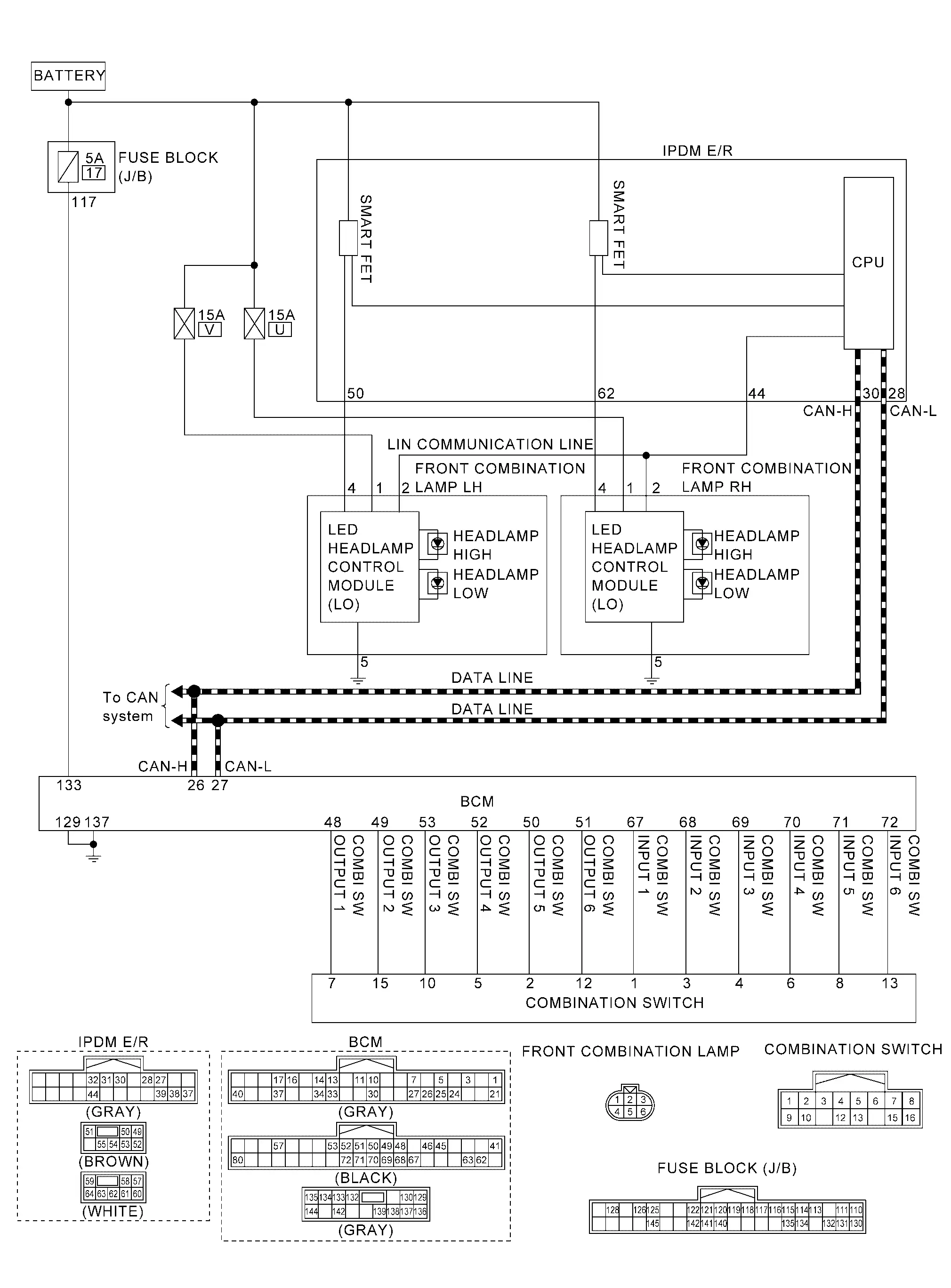
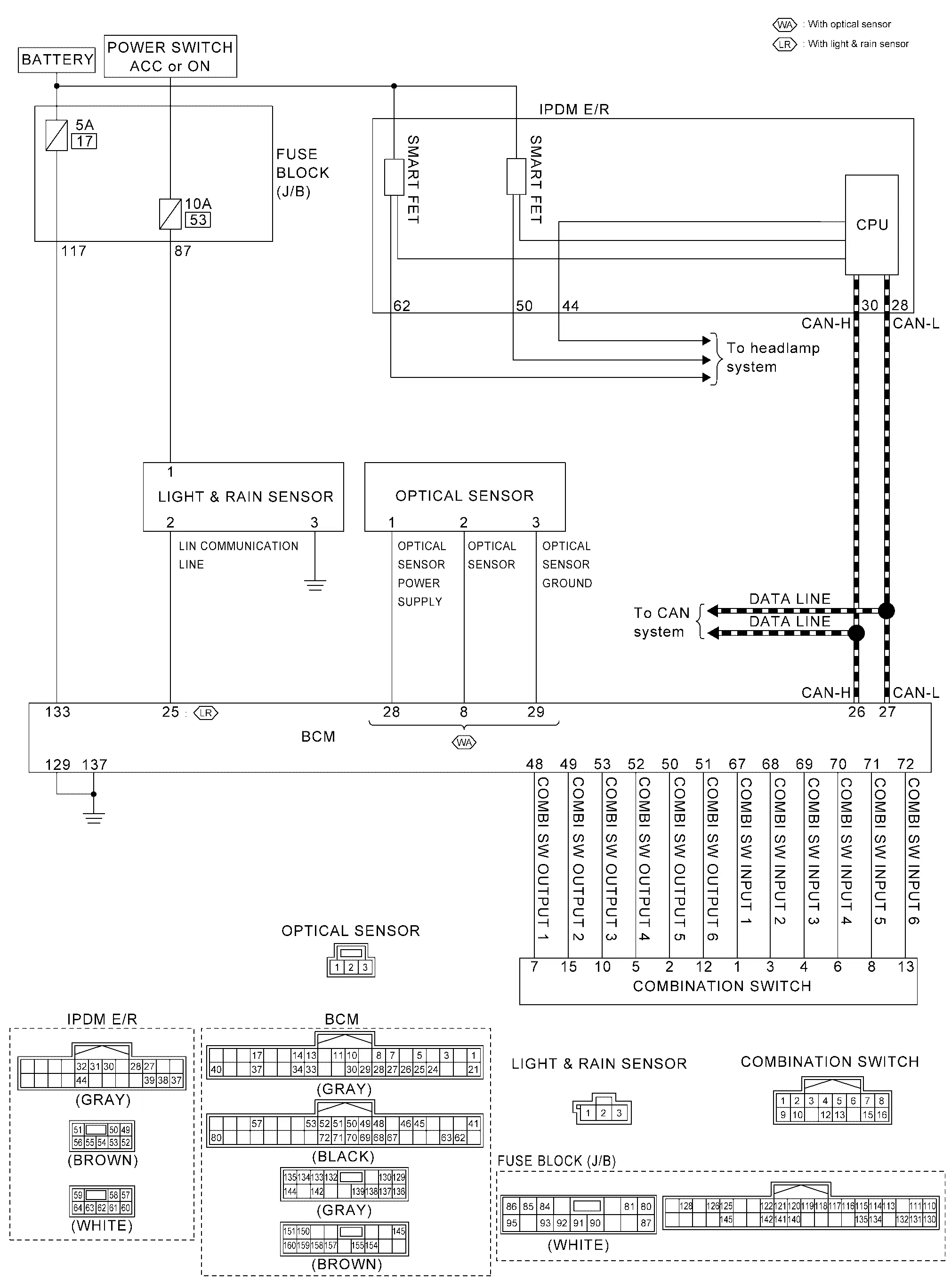
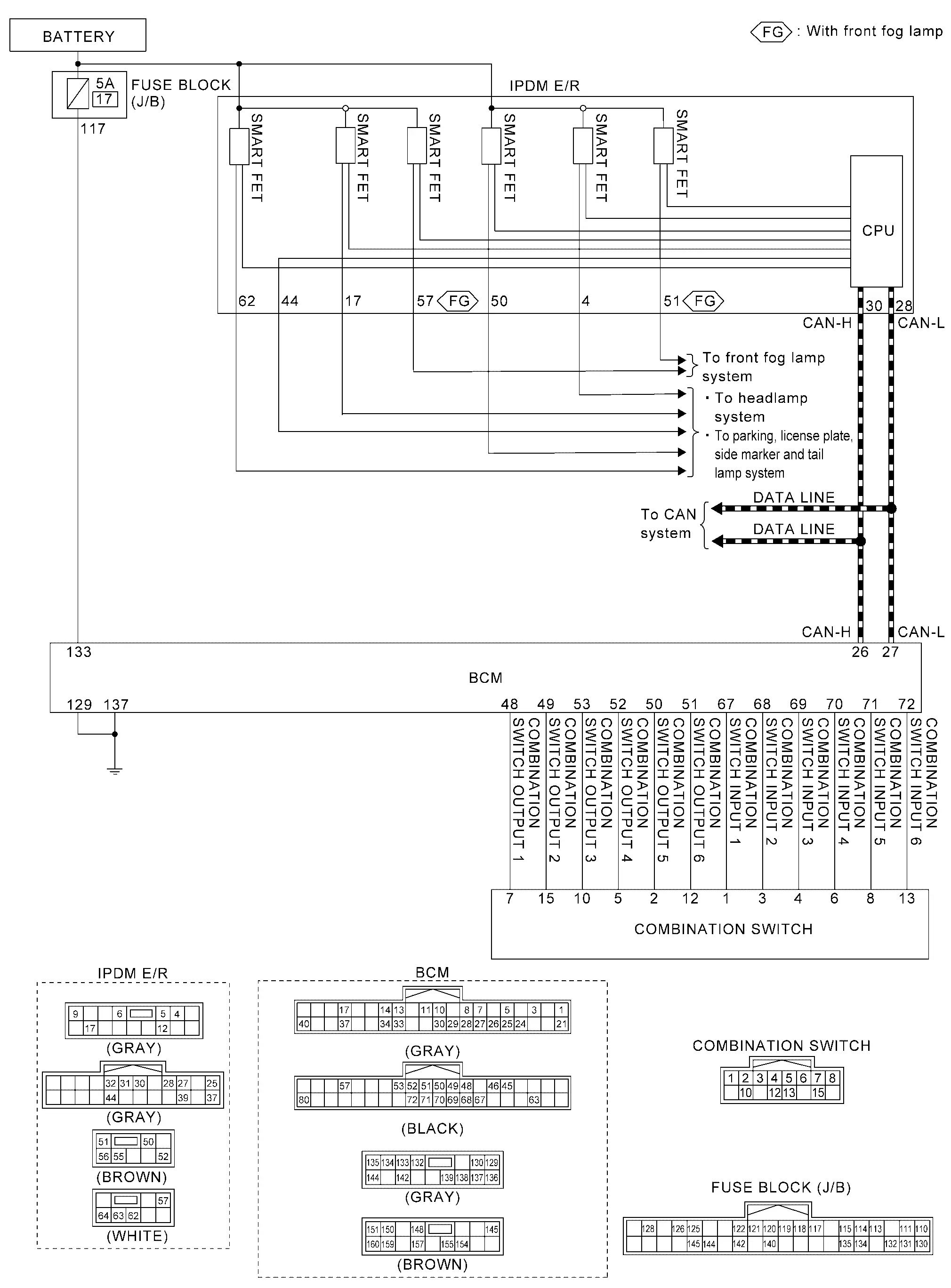
Circuit Diagram
Fail-safe
FAIL-SAFE CONTROL BY DTC
IPDM E/R performs fail-safe control when any DTC are detected.
| DTC No. | CONSULT display | Fail-safe |
|---|---|---|
| B20E2-96 | LED headlamp RH |
|
| B20E3-96 | LED headlamp LH |
CAN COMMUNICATION CONTROL
When CAN communication with BCM is impossible, IPDM E/R performs fail-safe control. After CAN communication recovers normally, it also returns to normal control.
If No CAN Communication Is Available With BCM
| Control part | Fail-safe operation |
|---|---|
| Headlamp |
|
Intelligent Auto Light System Nissan Ariya
System Description
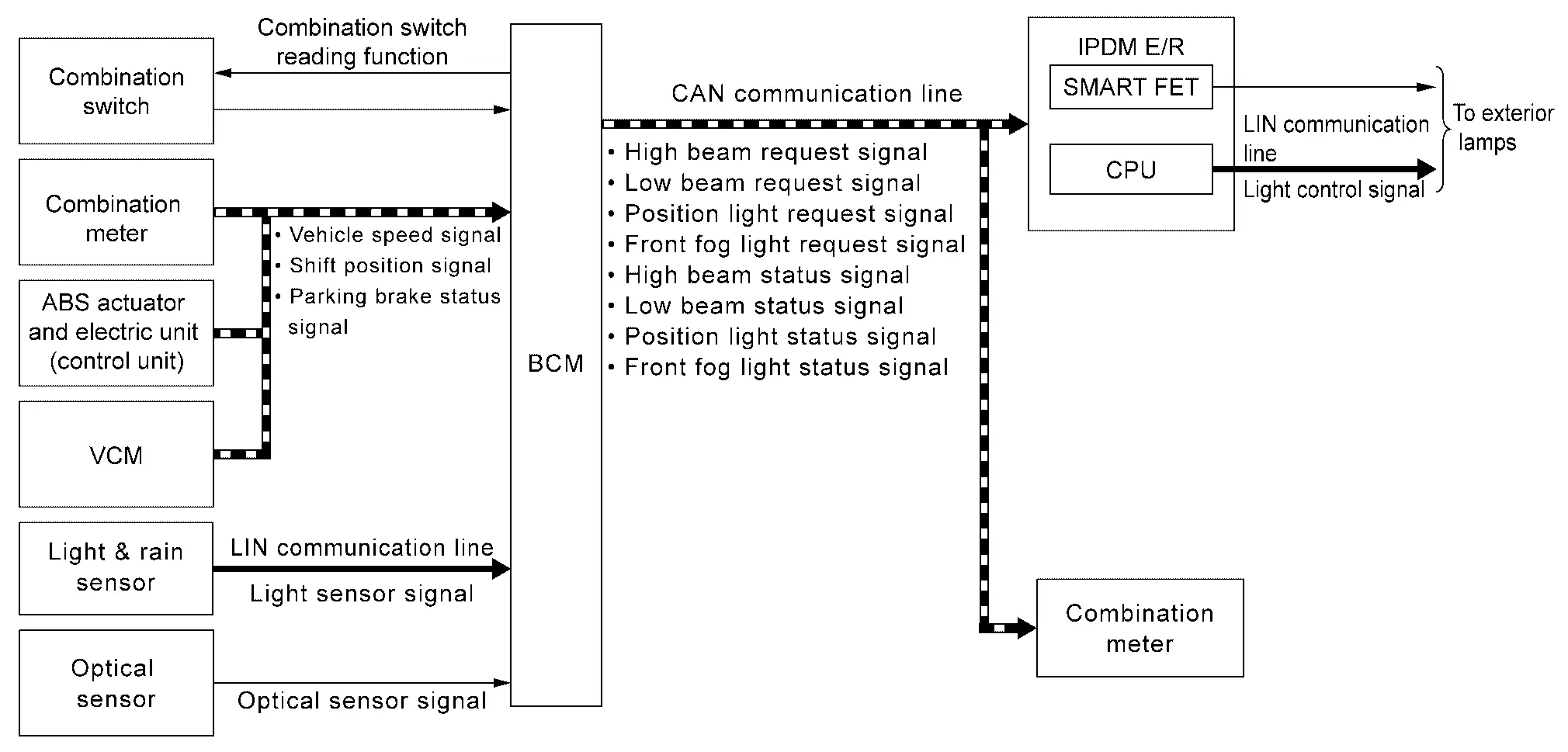
SYSTEM DIAGRAM
| Component | Function | |
|---|---|---|
| Light & rain sensor*1 | Refer to Light & Rain Sensor. | |
| Optical sensor*2 | Refer to Optical Sensor. | |
| IPDM E/R |
|
|
| BCM |
|
|
| Combination meter |
|
|
| ABS actuator and electric unit (control unit) | ABS actuator and electric unit (control unit) transmits Nissan Ariya vehicle speed signal to BCM via CAN communication. | |
| VCM | VCM transmits shift position signal to BCM via CAN communication. | |
| Combination switch | Lighting & turn signal switch | Inputs the each switch condition signal to BCM. |
*1: With light & rain sensor
*2: With optical sensor
OUTLINE
-
Intelligent auto light system is controlled by each function of BCM and IPDM E/R.
Control by BCM
-
Combination switch reading function
-
Auto light function
-
Wiper linked auto lighting function
-
Delay timer function
Control by IPDM E/R
-
Smart FET control function
-
LIN communication function
-
-
Intelligent auto light system has the auto light function, wiper linked auto lighting function and delay timer function.
-
Auto light function automatically turns ON/OFF the exterior lamps*, depending on the outside brightness.
-
Wiper linked auto lighting function automatically turns ON/OFF the exterior lamps* when the lighting switch is in the AUTO position, according to a front wiper operation.
-
Delay timer function turns the exterior lamps* OFF depending on the Nissan Ariya vehicle condition with the auto light function when the power switch is turned OFF.
-
*: Headlamp (LO/HI), front fog lamp, parking lamp, side marker lamp, license plate lamp and tail lamp.
NOTE:
-
Headlamp (HI) depend on the combination switch condition and the illumination judgment of high beam assist system. Refer to System Description.
-
Front fog lamp depend on the front fog lamp switch condition.
AUTO LIGHT FUNCTION
-
BCM detects the combination switch condition with the combination switch reading function.
-
BCM detects the Nissan Ariya vehicle condition that is required for auto light control with the following signals.
-
Parking brake status signal (received from combination meter via CAN communication)
-
Nissan Ariya Vehicle speed signal [received from ABS actuator and electric unit (control unit) via CAN communication]
-
Shift position signal (received from VCM via CAN communication)
-
-
BCM receives light sensor signal from the light & rain sensor via LIN communication. (With light & rain sensor)
-
BCM judges the ON/OFF status of the exterior lamp according to light control signal from light & rain sensor and the Nissan Ariya vehicle condition. (With light & rain sensor)
-
BCM supplies voltage to the optical sensor when the power switch is turned ON. (With optical sensor)
-
Optical sensor converts outside brightness (lux) to voltage and transmits the optical sensor signal to BCM. (With optical sensor)
-
When power switch is turned ON, BCM detects outside brightness from the optical sensor signal and judges ON/OFF condition of each exterior lamp, depending on the outside brightness condition. (With optical sensor)
-
BCM transmits each request signal to IPDM E/R and each status signal to combination meter via CAN communication, according to ON/OFF condition by the auto light function.
Lighting conditions for lighting switch AUTO (When all of the following conditions are satisfied)
-
Set the Nissan Ariya vehicle to READY
-
Parking brake is released or vehicle speed is 4 km/h (2.5 MPH) or more
-
Lighting judgment ON depending on the brightness outside of Nissan Ariya vehicle
Lighting off conditions for lighting switch AUTO (When any of the following conditions are satisfied)
-
Power switch OFF
-
Nissan Ariya Vehicle speed is 3 km/h (1.8 MPH) or less and parking brake is operated*
*: Only before releasing the parking brake. After releasing the parking brake, it will not turn lights OFF if the parking brake is operate again.
-
Lighting judgment OFF depending on the brightness outside of Nissan Ariya vehicle
Headlamp lighting conditions when the lighting switch is 1ST (When all of the following conditions are satisfied)
-
Set the Nissan Ariya vehicle to READY
-
Vehicle speed is 4 km/h (2.5 MPH) or more, or parking brake is released and other than select lever P range
-
Lighting judgment ON depending on the brightness outside of Nissan Ariya vehicle
Headlamp lighting off conditions when the lighting switch is 1ST (When any of the following conditions are satisfied)
-
Power switch OFF
-
Nissan Ariya Vehicle speed is 3 km/h (1.8 MPH) or less and parking brake is operated
-
Vehicle speed is 3 km/h (1.8 MPH) or less and select lever is P range
-
Lighting judgment OFF depending on the brightness outside of Nissan Ariya vehicle
-
WIPER LINKED AUTO LIGHTING FUNCTION
BCM turns each exterior lamp ON when the within 60 seconds detecting 4 operations of the front wiper while the lighting switch is in AUTO position.
NOTE:
BCM turns OFF the headlamps 3 seconds after the front wiper switch is turned OFF.
DELAY TIMER FUNCTION
BCM turns the exterior lamps OFF depending on the vehicle condition with the auto light function when the power switch is turned OFF.
-
Turns the exterior lamps OFF 30 seconds after the power switch is turned OFF.
-
Delay timer function turns OFF, when the vehiccle READY condition or the lighting switch is other than AUTO.
NOTE:
When any position other than the lighting switch AUTO is set, the auto light function switches to the exterior lamp battery saver function.
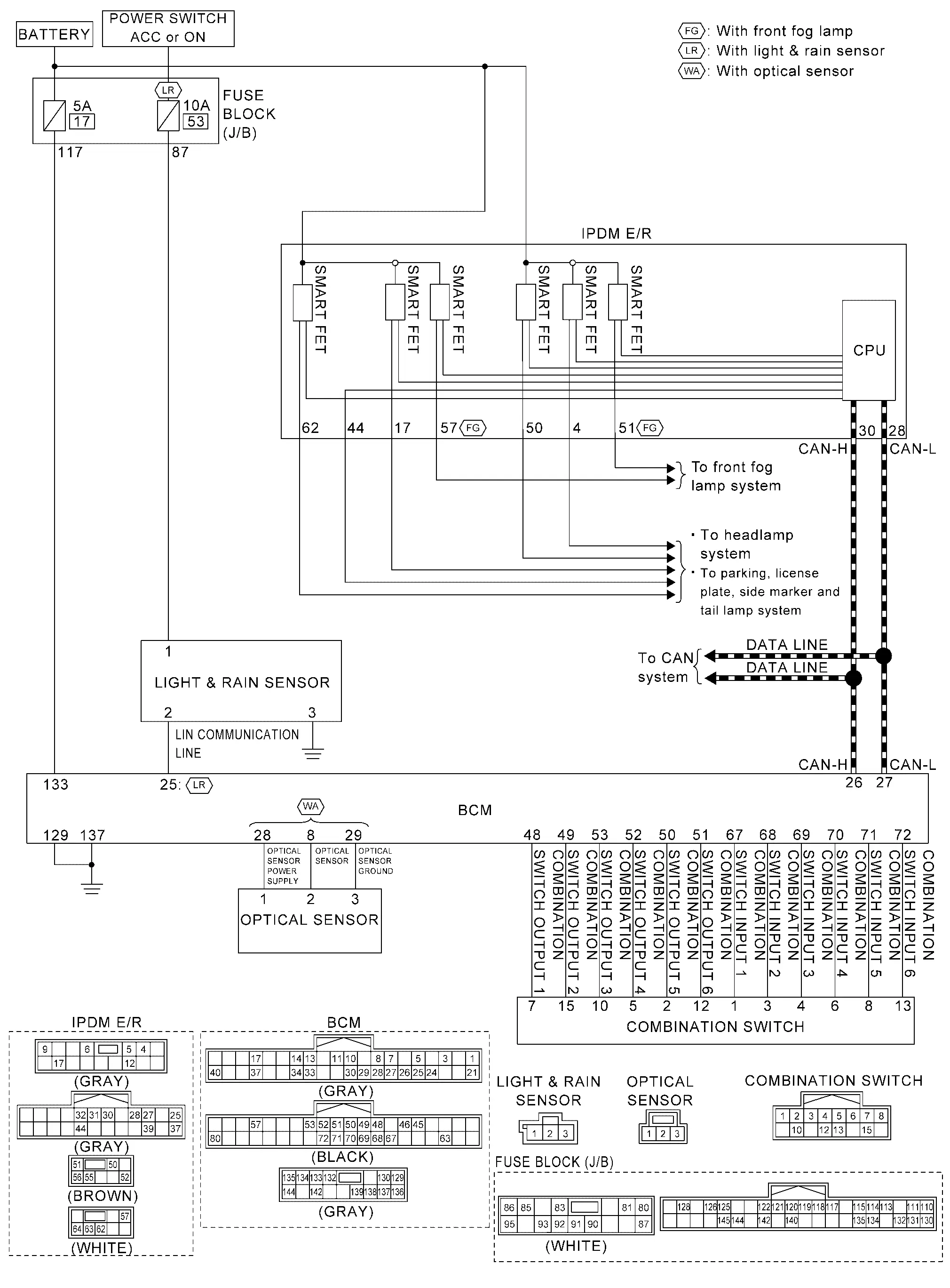
Circuit Diagram
Fail-safe
FAIL-SAFE CONTROL BY DTC
BCM performs fail-safe control when any DTC are detected.
| Display contents of CONSULT | Fail-safe |
|---|---|
| B2C96-49: Light sensor | Turns ON the headlamp (LO) |
High Beam Assist System Nissan Ariya 1st generation
System Description
SYSTEM DIAGRAM
| Component | Function | |
|---|---|---|
| Light & rain sensor*1 | Refer to Light & Rain Sensor. | |
| Optical sensor*2 | Refer to Optical Sensor. | |
| Front camera unit | Judges the Nissan Ariya vehicle status from each signal in order to control the high beam assist control. | |
| IPDM E/R | Transmits the light control signal (via LIN communication) and control signal to the load according with the request from BCM via CAN communication. | |
| BCM |
|
|
| Combination meter | Turns the indicator lamp ON/OFF according to the status from BCM via CAN communication. | |
| ABS actuator and electric unit (control unit) | ABS actuator and electric unit (control unit) transmits Nissan Ariya vehicle speed signal to front camera unit via CAN communication. | |
| Combination switch | Lighting & turn signal switch | Inputs the each switch condition signal to BCM. |
*1: With light & rain sensor
*2: With optical sensor
OUTLINE
-
High beam assist system is a system that can reduce the driver's switch operation load. The system automatically switches the headlamp to the low beam mode when a Nissan Ariya vehicle ahead or an oncoming vehicle appears, while driving the vehicle with the headlamps in high beam mode at night.
-
When the high beam assist system operation permission conditions are satisfied, the high beam assist indicator lamp in the combination meter turns ON and informs that the high beam assist is in operation.
-
High beam assist system is controlled by each function of BCM, IPDM E/R and front camera unit.
Control by BCM
-
Combination switch reading function
-
Auto light function
-
High beam assist control function
-
Headlamp control function
Control by IPDM E/R
-
Smart FET control function
-
LIN communication function
Control by front camera unit
-
High beam assist control function
-
OPERATION DESCRIPTION
-
BCM detects the combination switch condition with the combination switch reading function.
-
BCM transmits the high beam assist indicator lamp signal to the combination meter via CAN communication when the high beam assist system operation permission conditions are satisfied.
High beam assist system operation permission conditions
-
Set the Nissan Ariya vehicle to READY
-
Lighting switch 1ST or AUTO (Only when the illuminating judgement by auto light function is ON. Refer to System Description. ) (For Canada)
-
Lighting switch AUTO (Only when the illuminating judgement by auto light function is ON. Refer to System Description.) (Except for Canada)
-
High beam assist switch ON
-
-
Combination meter turns the high beam assist indicator lamp ON according to the high beam assist indicator lamp signal.
-
Front camera unit detects the Nissan Ariya vehicle status and ambient status that are required for high beam assist control with the following signals.
-
Nissan Ariya Vehicle speed signal [received from ABS actuator and electric unit (control unit) via CAN communication]
-
Ambient light signal (detect from front camera unit)
-
Image sensor signal (detect from front camera unit)
-
-
Front camera unit judges the current recommended beam according to the Nissan Ariya vehicle status and ambient condition, and transmits the high beam assist request signal (headlamp HI operation / headlamp LO operation) to BCM via CAN communication.
-
BCM switches the headlamp LO operation / headlamp HI operation according to high beam assist request signal while the high beam assist system operation permission conditions are satisfied. For headlamp operation, refer to System Description.
RECOMMENDED BEAM JUDGEMENT BY FRONT CAMERA UNIT
Headlamp HI Operation Request
Front camera unit requests the headlamp HI operation to BCM when all of following conditions are satisfied.
-
Detects the vehicle speed is approx. 30 km/h (19 MPH) or more.
-
Recognizes the ambient condition is dark.
-
Recognizes there is no oncoming Nissan Ariya vehicle or no vehicle ahead in front of the vehicle.
Headlamp LO Operation Request
Front camera unit requests the headlamp LO operation to BCM when either of following conditions is satisfied.
-
Detects the vehicle speed is approx. 20 km/h (13 MPH) or less.
-
Recognizes the ambient condition is bright.
-
Recognizes there is oncoming Nissan Ariya vehicle or vehicle ahead in front of the vehicle.
Circuit Diagram
Headlamp Aiming Control (manual) Nissan Ariya 2023
System Description
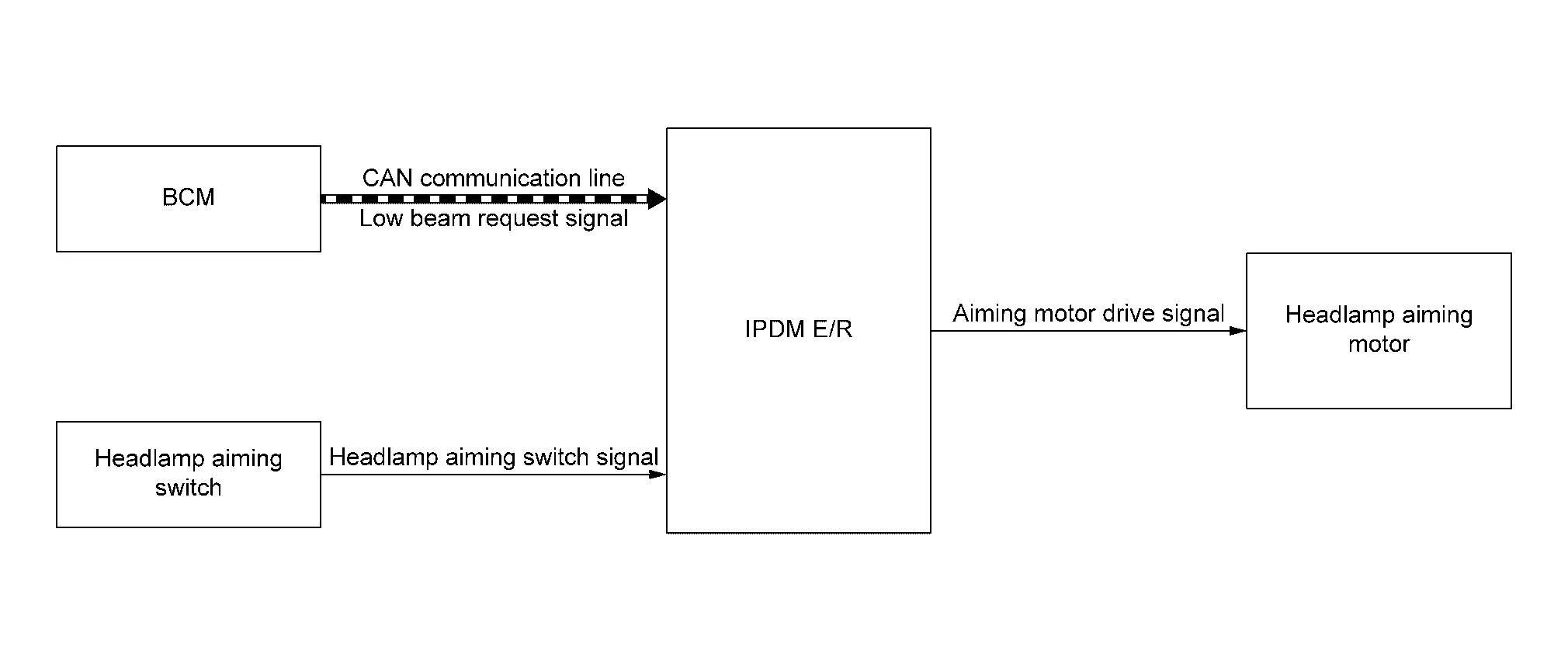
SYSTEM DIAGRAM
| Component | Function | |
|---|---|---|
| Headlamp | Headlamp aiming motor | Refer to Headlamp Aiming Motor. |
| Headlamp aiming switch | Refer to Headlamp Aiming Switch. | |
| IPDM E/R | IPDM E/R receives headlamp aiming switch signal and controls height of the optical axis of the headlamp. | |
| BCM | BCM transmits low beam request signal to IPDM E/R via CAN communication. | |
OUTLINE
-
Headlamp aiming control system is controlled by IPDM E/R.
-
IPDM E/R controls the headlamp light axis height appropriately depending on the headlamp aiming switch setting.
-
IPDM E/R detects the Nissan Ariya vehicle condition necessary for the headlamp aiming motor control with the following signals.
-
Headlamp aiming switch signal (inputted from headlamp aiming switch)
-
Low beam request signal (received from BCM via CAN communication)
-
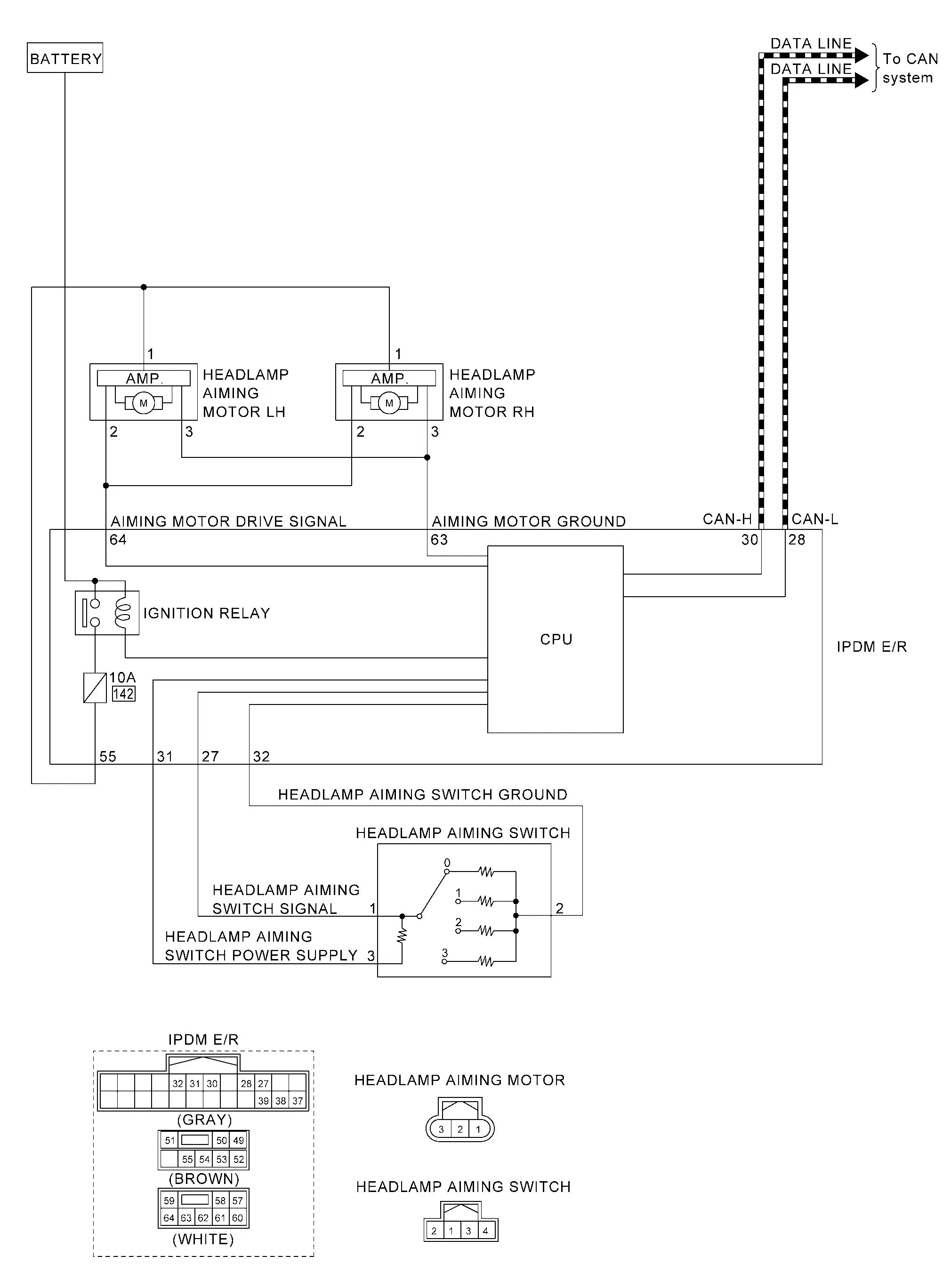
HEADLAMP MANUAL AIMING OPERATION
-
IPDM E/R receives the headlamp aiming switch signal from headlamp aiming switch and detect the leveling position.
-
IPDM E/R controls the height of the optical axis of the headlamp depending on the leveling position.
-
IPDM E/R outputs aiming motor drive signal when operating conditions are satisfied.
Operating condition (when all of the following conditions are satisfied)
-
Power switch ON
-
Headlamp (LO) ON
-
Circuit Diagram
Fail-safe
FAIL-SAFE CONTROL BY DTC
IPDM E/R performs fail-safe control when any DTC are detected.
| DTC No. | CONSULT display | Fail-safe |
|---|---|---|
| B1C07-11 | Aiming motor drive signal | Right and left headlamp aiming motors stop at the position when DTC is detected. |
| B1C07-12 | Aiming motor drive signal | |
| B1C07-62 | Aiming motor drive signal | |
| B1C10-12 | Manual switch | |
| B1C10-14 | Manual switch | |
| B1C10-1C | Manual switch | |
| B20DB-55 | Height sensor initialize not done | Right and left headlamp aiming motors fix at the initial position. |
Daytime Running Light System Nissan Ariya
System Description
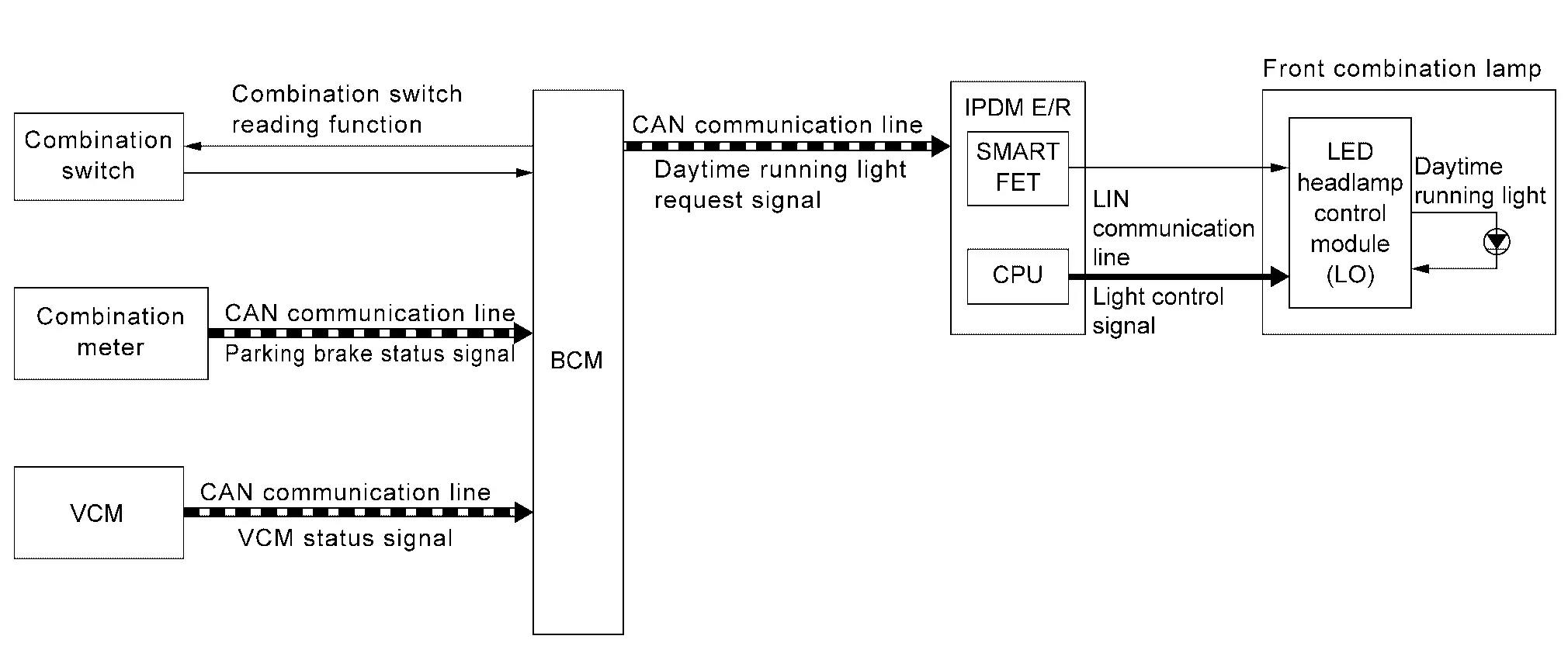
SYSTEM DIAGRAM
| Component | Function | |
|---|---|---|
| Front combination lamp | Daytime running light |
|
| LED headlamp control module (LO) | Refer to LED Headlamp Control Module (LO). | |
| IPDM E/R | Transmits the light control signal (via LIN communication) and control signal to the LED headlamp control module (LO) according with the request from BCM via CAN communication. | |
| BCM |
|
|
| Combination meter | Combination meter transmits parking brake status signal to BCM via CAN communication. | |
| VCM | VCM transmits VCM status signal to BCM via CAN communication. | |
| Combination switch | Lighting & turn signal switch | Inputs the each switch condition signal to BCM. |
OUTLINE
Daytime running light is controlled by daytime running light control function and combination switch reading function of BCM, and smart FET control function and LIN communication function of IPDM E/R.
DAYTIME RUNNING LIGHT OPERATION
-
BCM detects the combination switch condition by the combination switch reading function.
-
BCM detects Nissan Ariya vehicle condition depending on the VCM status signal and parking brake status signal (received from VCM and combination meter via CAN communication).
-
BCM transmits the daytime running light request signal to IPDM E/R via CAN communication according to the daytime running light ON condition.
Daytime running light ON condition
-
Set the Nissan Ariya vehicle to READY, parking brake release and any following conditions are satisfied.
Except for Canada
-
Lighting switch OFF
-
Lighting switch 1ST
-
Lighting switch AUTO (Only when the illumination judgement by auto light function is OFF. Refer to System Description.)
For Canada
-
Lighting switch 1ST (Only when the illumination judgement by auto light function is OFF. Refer to System Description. )
-
Lighting switch AUTO (Only when the illumination judgement by auto light function is OFF. Refer to System Description.)
-
-
-
IPDM E/R turns the integrated smart FET ON according to daytime running light request signal, and transmits the control signal to LED headlamp control module (LO).
-
IPDM E/R transmits the light control signal (via LIN communication) to LED headlamp control module (LO) according to daytime running light request signal.
-
LED headlamp control module (LO) turns the daytime running light ON according to the light control signal (via LIN communication) and control signal from IPDM E/R.
NOTE:
Daytime running light and parking lamp use a common light source. When the daytime running light is turned ON while parking lamp is ON, the parking lamp/daytime running light is brightening.
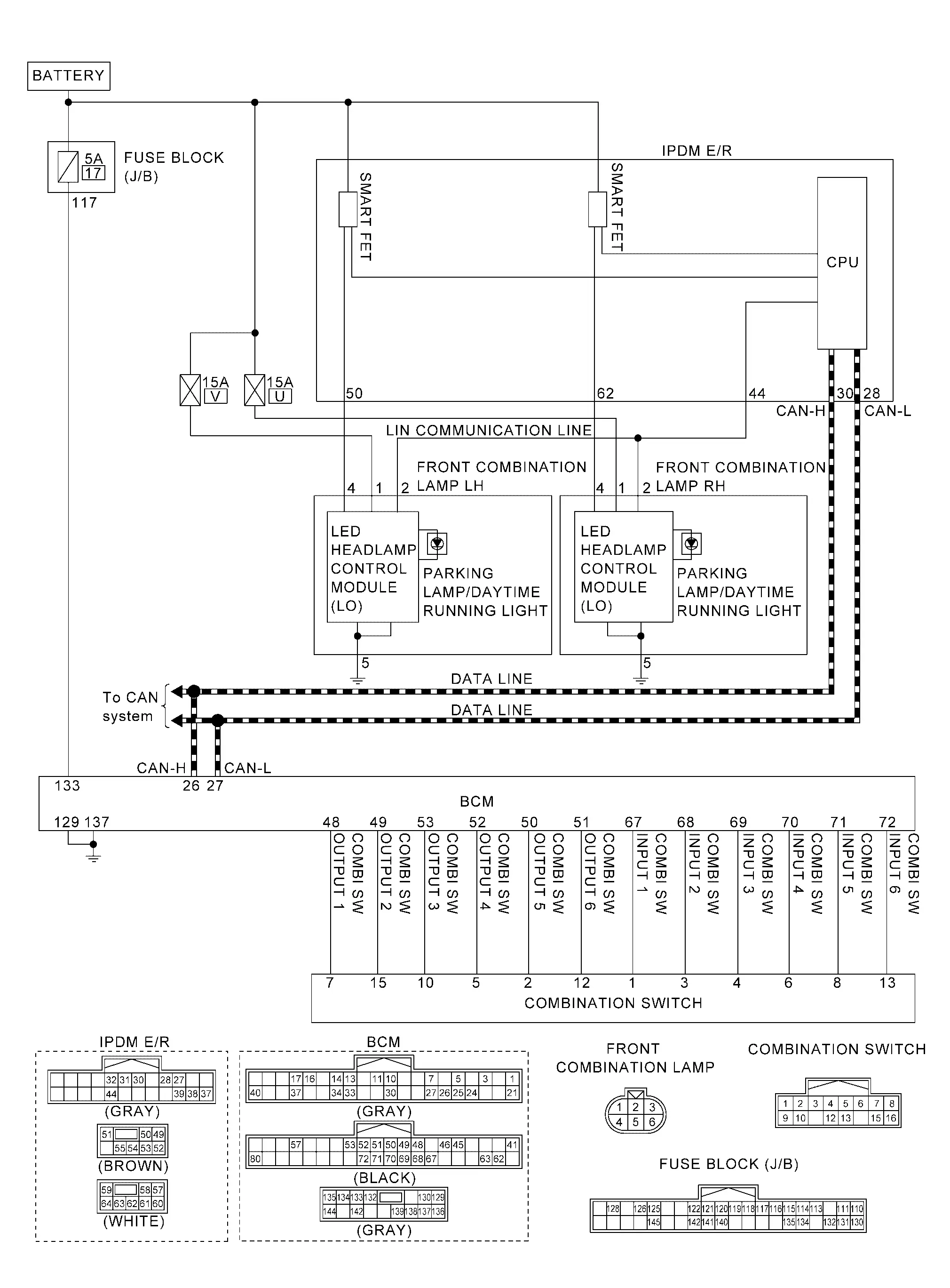
Circuit Diagram
Fail-safe
CAN COMMUNICATION CONTROL
When CAN communication with BCM is impossible, IPDM E/R performs fail-safe control. After CAN communication recovers normally, it also returns to normal control.
If No CAN Communication Is Available With BCM
| Control part | Fail-safe operation |
|---|---|
| Daytime running light | Daytime running light: OFF |
Turn Signal and Hazard Warning Lamp System Nissan Ariya
System Description
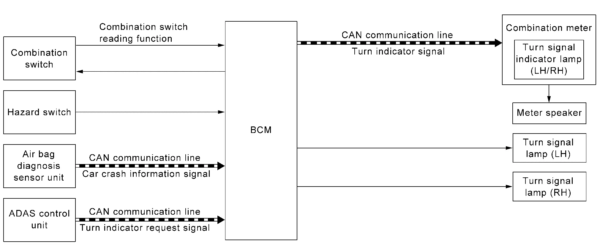
SYSTEM DIAGRAM
| Component | Function | |
|---|---|---|
| Front combination lamp | Front turn signal lamp |
|
| Door mirror | Side turn signal lamp |
|
| Rear combination lamp (body side) | Rear turn signal lamp |
|
| Rear combination lamp (back door side) | Rear turn signal lamp |
|
| Hazard switch | Refer to Hazard Switch. | |
| BCM |
|
|
| Air bag diagnosis sensor unit | When the air bag operates, a request is transmitted to BCM (via CAN communication) to blinks the hazard warning lamp. | |
| ADAS control unit 2 | When the overtaking support function operates, a request is transmitted to BCM (via CAN communication) to blinks the hazard warning lamp. | |
| Combination meter | Blinks the turn signal indicator lamp and outputs the turn signal operating sound to meter speaker according to the status from BCM via CAN communication. | |
| Meter speaker | Outputs the turn signal operating sound according to the signal from combination meter. | |
| Combination switch | Lighting & turn signal switch | Inputs the each switch condition signal to BCM. |
OUTLINE
Turn signal lamp and hazard warning lamp is controlled by combination switch reading function and the flasher control function of BCM.
TURN SIGNAL LAMP OPERATION
-
BCM detects the combination switch condition by the combination switch reading function.
-
BCM supplies voltage to the right (left) turn signal lamp circuit when the power switch is ON and the turn signal switch is in the right (left) position. BCM blinks the turn signal lamp.
HAZARD WARNING LAMP OPERATION
BCM supplies voltage to both turn signal lamp circuits when the hazard switch is ON. BCM blinks the hazard warning lamp.
TURN SIGNAL INDICATOR LAMP AND TURN SIGNAL SOUND OPERATION
-
BCM transmits the turn indicator signal to the combination meter via CAN communication while the turn signal lamp and the hazard warning lamp are operating.
-
Combination meter outputs the turn signal sound to the meter speaker while blinking the turn signal indicator lamp according to the turn indicator signal.
-
Meter speaker outputs the turn signal sound according to the signal from combination meter.
3-TIME FLASHER FUNCTION
By a short touch of the turn signal lever, BCM blinks the turn signal lamps 3 times in the selected direction.
NOTE:
-
When the turn signal switch is operated briefly to the opposite side of the blinking during blinking 3 times by 3-time flasher function, the 3 blinks of the turn signal lamp will be canceled. (With ProPILOT Assist 2.0)
-
When the turn signal switch is operated briefly to the opposite side of the blinking during blinking 3 times by 3-time flasher function, the turn signal lamp on the opposite side will switch to blinking 3 times. (Without ProPILOT Assist 2.0)
HIGH FLASHER OPERATION
-
BCM detects the turn signal lamp circuit status from the current value.
-
BCM increases the turn signal lamp blinking speed if the bulb or harness open is detected with the turn signal lamp operating.
NOTE:
The blinking speed is normal while operating the hazard warning lamp.
REAR TURN SIGNAL LAMP DIAGNOSIS CIRCUIT
-
Between rear combination lamp (body side) and rear combination lamp (back door side) has diagnosis circuit of rear turn signal circuit.
-
When either body side or back door side detects the abnormal state, the blink of body side or back door side is stopped.
-
When BCM detects the blink stop state of rear turn signal circuit (right or left), it operates turn signal lamp of the corresponding circuit in high flasher operation.
OVERTAKING SUPPORT FUNCTION
-
When lane changes ADAS control unit 2 transmits turn indicator request signal to BCM via CAN communication. (For details about the overtaking support function. Refer to System Description.)
-
When BCM receives turn indicator request signal, it supplies power to the turn signal lamp RH (LH) circuit and blinks turn signal lamp. When the lane change by overtaking support function is completed the turn signal lamp is turned OFF.
AUTO HAZARD FUNCTION
-
Air bag diagnosis sensor unit transmits car crash information signal to BCM via CAN communication, when air bag diagnosis sensor unit detects strong impact to the Nissan Ariya vehicle body while power switch is ON.
-
When car crash information signal received from air bag diagnosis sensor unit is detected, BCM supplies voltage to each turn signal lamp system and hazard lamp blinks.
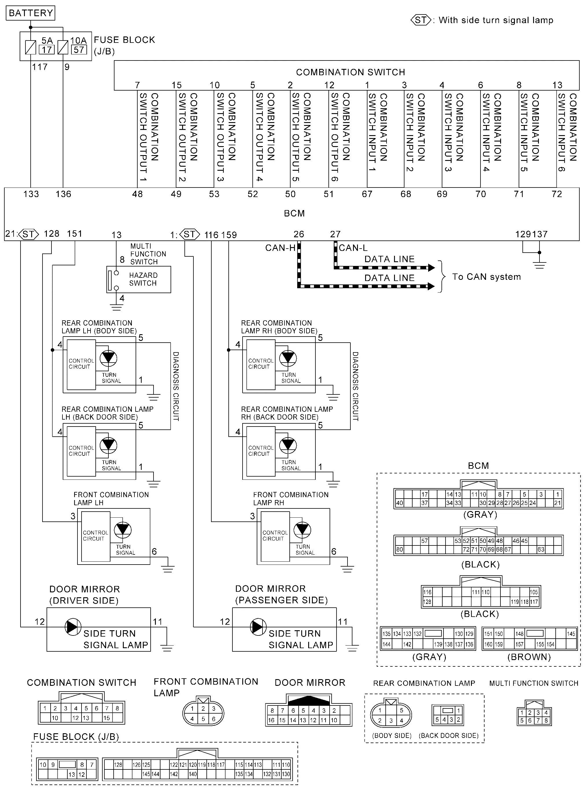
Circuit Diagram
Parking, License Plate, Side Marker and Tail Lamp System Nissan Ariya first Gen
System Description
SYSTEM DIAGRAM
| Component | Function | |
|---|---|---|
| Front combination lamp | Parking lamp |
|
| LED headlamp control module (LO) | Refer to LED Headlamp Control Module (LO). | |
| Front side marker lamp |
|
|
| Rear combination lamp (body side) | Tail lamp |
|
| Rear side marker lamp |
|
|
| Rear combination lamp (back door side) | Tail lamp |
|
| License plate lamp |
|
|
| IPDM E/R |
|
|
| BCM |
|
|
| Combination meter | Turns the position lamp indicator lamp ON/OFF according to the status from BCM via CAN communication. | |
| Intelligent Key unit | Transmits the door lock/unlock request signal to BCM (via CAN communication) from door lock/unlock button operation. | |
| Combination switch | Lighting & turn signal switch | Inputs the each switch condition signal to BCM. |
| Door lock assembly | Front door switch | Detects the front door condition (open or close), and inputs the door switch signal to BCM. |
| Rear door switch | Detects the rear door condition (open or close), and inputs the door switch signal to BCM. | |
| Back door switch | Detects the back door condition (open or close), and inputs the door switch signal to BCM. | |
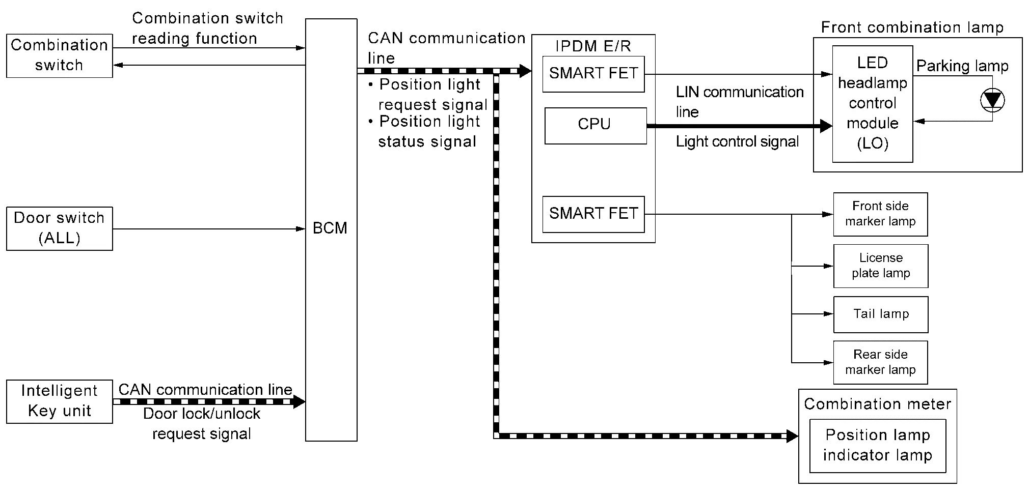
OUTLINE
Parking, license plate, side marker and tail lamps are controlled by combination switch reading function and parking, license plate, side marker and tail lamps control function of BCM, and smart FET control function and LIN communication function of IPDM E/R.
PARKING, LICENSE PLATE, SIDE MARKER AND TAIL LAMPS OPERATION
-
BCM detects the combination switch condition by the combination switch reading function.
-
BCM transmits the position light request signal to IPDM E/R and position light status signal to the combination meter via CAN communication according to the parking, SIDE MARKER license plate and tail lamps ON condition.
Parking, license plate, side marker and tail lamps ON condition (when any of the following conditions are satisfied)
-
Lighting switch 1ST
-
Lighting switch 2ND
-
Lighting switch AUTO (Only when the illumination judgement by auto light function is ON. Refer to System Description.)
-
-
IPDM E/R turns the integrated smart FET ON and turns the license plate, side marker and tail lamps ON according to the position light request signal.
-
IPDM E/R turns the integrated smart FET ON according to position light request signal, and transmits the control signal to LED headlamp control module (LO).
-
IPDM E/R transmits the light control signal (via LIN communication) to LED headlamp control module (LO) according to position light request signal.
-
LED headlamp control module (LO) turns the parking lamp ON according to the light control signal (via LIN communication) and control signal from IPDM E/R.
-
Combination meter turns the position lamp indicator lamp ON according to the position light status signal.
NOTE:
Parking lamp and daytime running light use a common light source. When the parking, license plate, side marker and tail lamps are turned ON while daytime running light is ON, the parking lamp/daytime running light is dimmed.
SIGNATURE LIGHT FUNCTION
Description
The signature light function is a function that turns ON the parking lamp, license plate lamp, side marker lamp and tail lamp for a set period of time when the doors are locked or unlocked from outside the Nissan Ariya vehicle, or doors opened.
NOTE:
ON/OFF of signature light function can be changed in the Nissan Ariya vehicle settings of the combination meter.
Operation Description
BCM transmits the position light request signal to IPDM E/R and position light status signal to the combination meter via CAN communication according to the signature light function ON condition.
Signature light function ON condition (Operation when doors are unlocked)
-
When all of the following conditions are satisfied, the signature light function operates when door unlock operation is performed from outside the Nissan Ariya vehicle (Intelligent Key, door request switch, or one touch sensor, etc.).
-
Power switch: OFF
-
Door open/close status: All door close
-
Door lock status: All door lock
-
-
When any of the following conditions is satisfied while the signature light function is operating, the signature light function stops.
-
Set the Nissan Ariya vehicle to READY
-
Lighting switch other than AUTO
-
Since signature light function ON, approx. 30 seconds are passed.
NOTE:
When door lock operation is performed with the Intelligent Key or door request switch, or one touch sensor, the system changes to operation when doors are locked
-
Signature light function ON condition (Operation when doors are locked)
-
When all of the following conditions are satisfied, the signature light function operates when door lock operation is performed from outside the Nissan Ariya vehicle (Intelligent Key or door request switch, or one touch sensor, etc.).
-
Power switch: OFF
-
Door open/close status: All door close
-
Door lock status: All door unlock
-
-
When any of the following conditions is satisfied while the signature light function is operating, the signature light function stops.
-
Set the Nissan Ariya vehicle to READY
-
Lighting switch other than AUTO
-
Since signature light function ON, approx. 15 seconds are passed.
NOTE:
When door unlock operation is performed with the Intelligent Key or door request switch, or one touch sensor, the system changes to operation when doors are unlocked.
-
Signature light function ON condition (operation when doors opened)
-
When all of the following conditions are satisfied, the signature light function operates.
-
Power switch: Set the Nissan Ariya vehicle to READY ⇒ OFF
-
Door open/close status: All door close ⇒ Any door open
NOTE:
According to exterior lamp battery saver function, all lamps are turned off when lamps are ON and power switch is turned OFF from READY condition. Then when all doors are opened, the signature light function is operated.
-
-
When any of the following conditions is satisfied while the signature light function is operating, the signature light function stops.
-
Set the Nissan Ariya vehicle to READY
-
Lighting switch other than AUTO
-
Since signature light function ON, approx. 15 seconds are passed.
NOTE:
When door lock operation is performed with the Intelligent Key, door request switch, or one touch sensor, the system changes to operation when doors are locked.
-
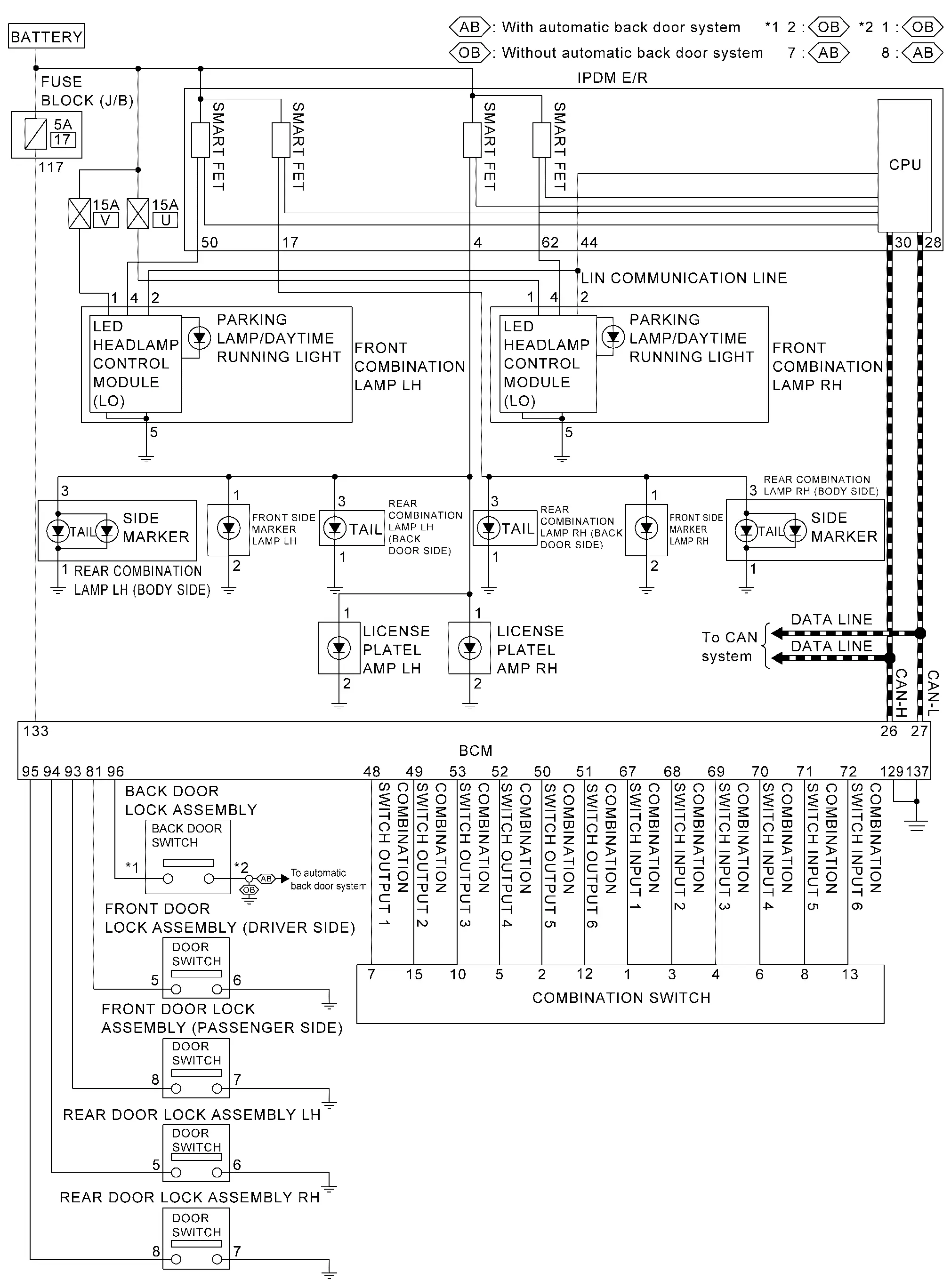
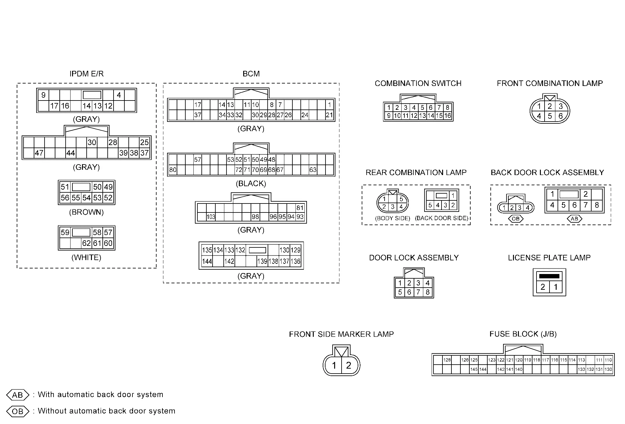
Circuit Diagram
Fail-safe
FAIL-SAFE CONTROL BY DTC
IPDM E/R performs fail-safe control when any DTC are detected.
| DTC No. | CONSULT display | Fail-safe |
|---|---|---|
| B20D4-11 | Tail lamp LH power supply circuit |
Shuts off the power supply to the following power supply circuits* until the license plate lamp, side marker lamp and tail lamp ON conditions are no longer satisfied.
|
CAN COMMUNICATION CONTROL
When CAN communication with BCM is impossible, IPDM E/R performs fail-safe control. After CAN communication recovers normally, it also returns to normal control.
If No CAN Communication Is Available With BCM
| Control part | Fail-safe operation |
|---|---|
|
|
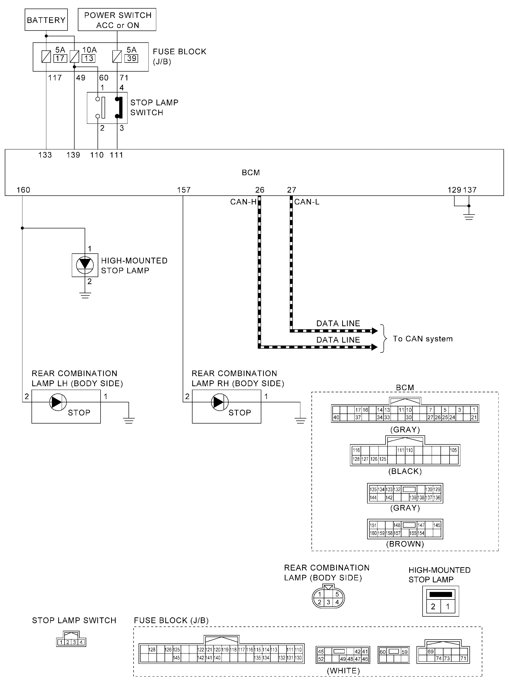
Stop Lamp System Nissan Ariya SUV
System Description
SYSTEM DIAGRAM
| Component | Function | |
|---|---|---|
| Rear combination lamp (body side) | Stop lamp |
|
| High-mounted stop lamp |
|
|
| Stop lamp switch | Refer to Stop Lamp Switch. | |
| BCM | Judges the Nissan Ariya vehicle status from each signal, and turns the stop lamp and high-mounted stop lamp ON. | |
| ADAS control unit 2 | When the automatic emergency braking operates, a request is transmitted to BCM (CAN communication) to turn ON the stop lamp. | |
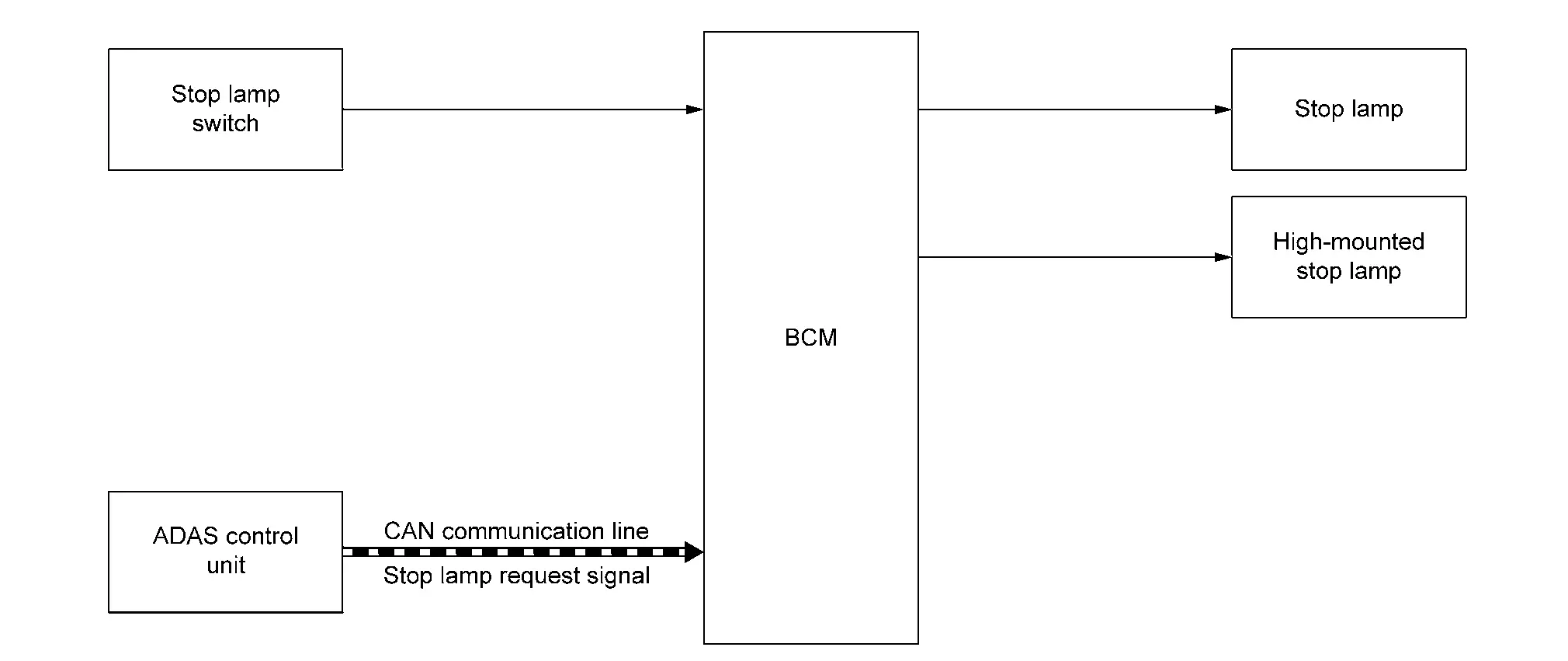
OUTLINE
Stop lamp and high-mounted stop lamp is controlled by stop lamp switch reading function and the stop lamp and high-mounted stop lamp control function of BCM and automatic emergency braking function of ADAS control unit 2.
STOP LAMP AND HIGH-MOUNTED STOP LAMP OPERATION
-
BCM detects the brake pedal position status from stop lamp switch.
-
BCM supplies voltage to stop lamp and high-mounted stop lamp according to the stop lamp and high-mounted stop lamp ON condition.
Stop lamp and high-mounted stop lamp ON condition
-
Brake pedal is depressed
-
AUTOMATIC EMERGENCY BRAKING FUNCTION
-
When the automatic emergency braking operates, the ADAS control unit 2 transmits the stop lamp request signal to BCM via CAN communication. (For details about the automatic emergency braking. Refer to System Description.)
-
When BCM receives the stop lamp request signal from the ADAS control unit 2, it supplies power to the stop lamp and high-mounted stop lamp systems, turning ON the stop lamp and high-mounted stop lamp.
Circuit Diagram
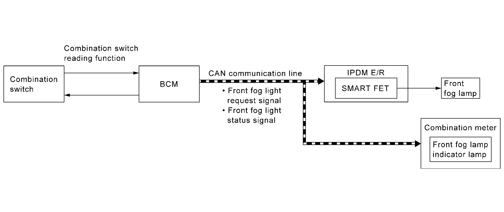
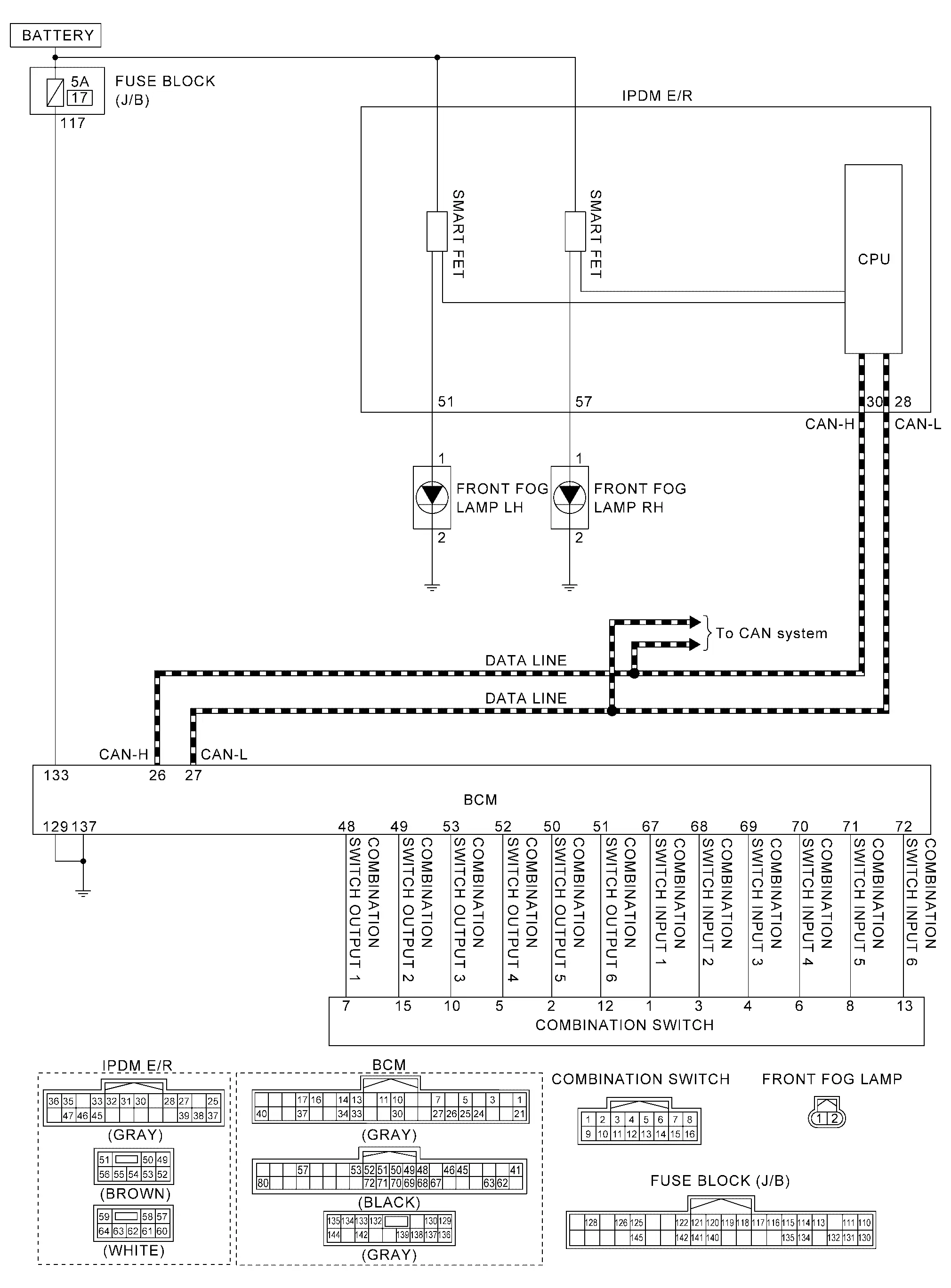
Front Fog Lamp System Nissan Ariya 2026
System Description
SYSTEM DIAGRAM
| Component | Function | |
|---|---|---|
| Front fog lamp |
|
|
| IPDM E/R | Controls the integrated smart FET, and supplies voltage to the front fog lamp according with the request from BCM via CAN communication. | |
| BCM |
|
|
| Combination meter | Turns the front fog lamp indicator lamp ON/OFF according to the status from BCM via CAN communication. | |
| Combination switch | Lighting & turn signal switch | Inputs the each switch condition signal to BCM. |
OUTLINE
Front fog lamp is controlled by combination switch reading function and front fog lamp control function of BCM, and smart FET control function of IPDM E/R.
FRONT FOG LAMP OPERATION
-
BCM detects the combination switch condition by the combination switch reading function.
-
BCM transmits the front fog light request signal to IPDM E/R and front fog light status signal to the combination meter via CAN communication according to the front fog lamp ON condition.
Front fog lamp ON condition
-
Front fog lamp switch is turned from OFF to ON, and any of the following conditions are satisfied.
-
Lighting switch 2ND
-
Lighting switch AUTO (Only when the illumination judgement by auto light function is ON. Refer to System Description.)
-
-
-
IPDM E/R turns the integrated smart FET ON, and turns the front fog lamp ON according to the front fog light request signal.
-
Combination meter turns the front fog lamp indicator lamp ON according to the front fog light status signal.
Circuit Diagram
Fail-safe
FAIL-SAFE CONTROL BY DTC
IPDM E/R performs fail-safe control when any DTC are detected.
| DTC No. | CONSULT display | Fail-safe |
|---|---|---|
| B121A-11 | Front fog lamp LH power supply circuit | Shuts off the power supply to the front fog lamp LH power supply circuit until the front fog lamp ON conditions are no longer satisfied. |
| B1256-11 | Front fog lamp RH power supply circuit | Shuts off the power supply to the front fog lamp RH power supply circuit until the front fog lamp ON conditions are no longer satisfied. |
CAN COMMUNICATION CONTROL
When CAN communication with BCM is impossible, IPDM E/R performs fail-safe control. After CAN communication recovers normally, it also returns to normal control.
If No CAN Communication Is Available With BCM
| Control part | Fail-safe operation |
|---|---|
| Front fog lamp | Front fog lamp: OFF |
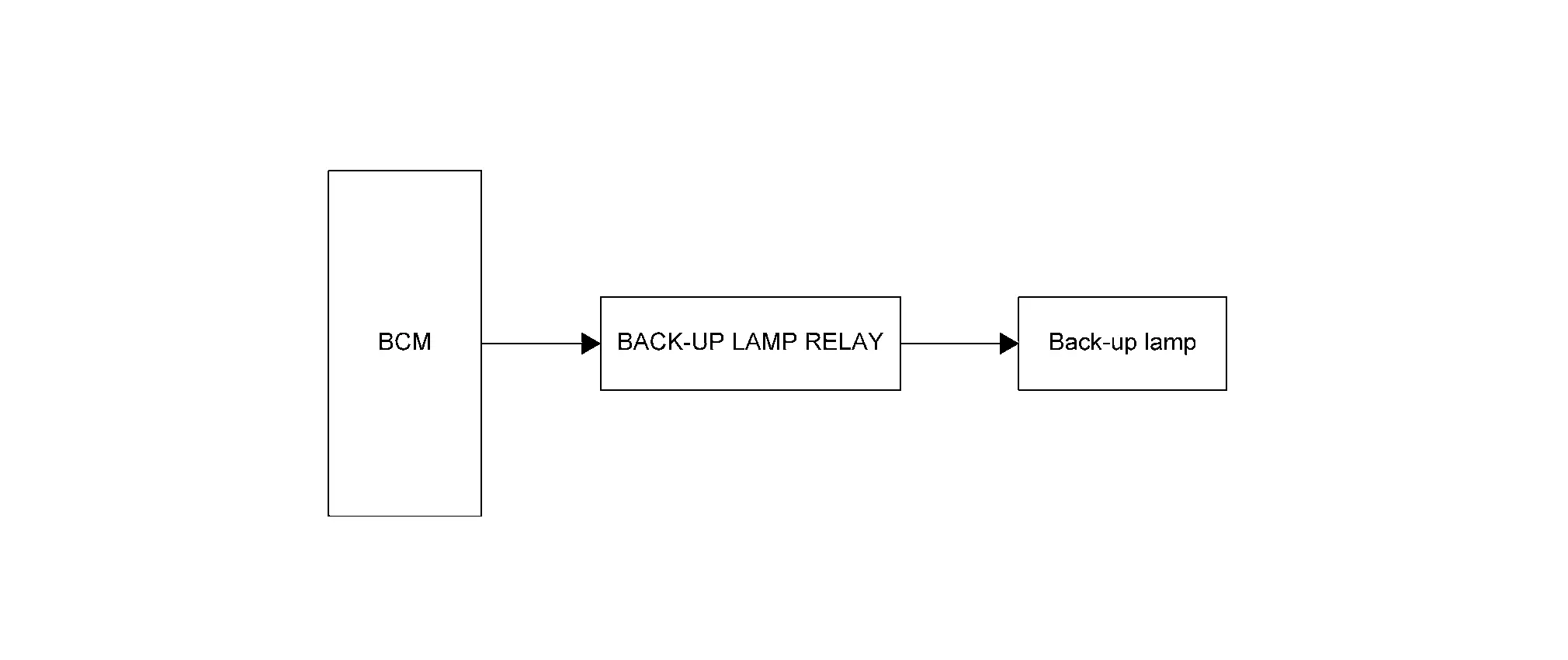
Back-Up Lamp System Nissan Ariya first Gen
System Description
SYSTEM DIAGRAM
| Component | Function | |
|---|---|---|
| Rear combination lamp (back door side) | Back-up lamp |
|
| Back-up lamp relay | Supplies the voltage to back-up lamp with the controlled by BCM. | |
| BCM | Controls the back-up lamp relay, and supplies voltage to the back-up lamp. | |
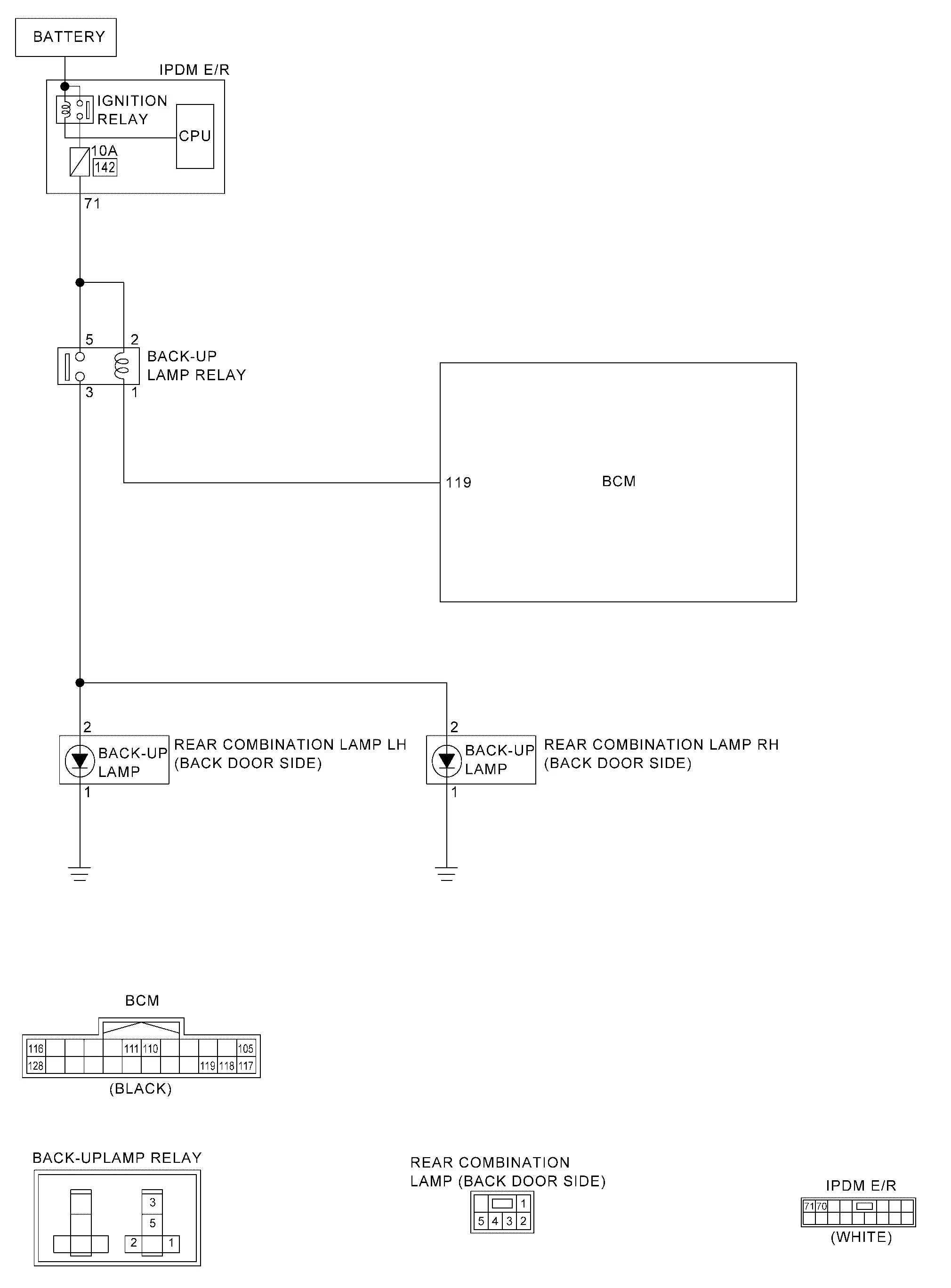
OUTLINE
Back-up lamp is controlled by back-up lamp control function of BCM.
BACK-UP LAMP OPERATION
-
BCM turns the back-up lamp relay ON, and turns the back-up lamp ON according to the back-up lamp ON conditions are satisfied.
Back-up lamp ON condition (when all of the following conditions are satisfied)
-
Set the Nissan Ariya vehicle to READY
-
Selector lever position R
-
Circuit Diagram
Exterior Lamp Battery Saver System Nissan Ariya SUV
System Description
SYSTEM DIAGRAM
| Component | Function | |
|---|---|---|
| IPDM E/R |
|
|
| BCM |
|
|
| Combination meter | Turns the indicator lamp ON/OFF according to the status from BCM via CAN communication. | |
| VCM | VCM transmits VCM status signal to BCM via CAN communication. | |
| Combination switch | Lighting & turn signal switch | Inputs the each switch condition signal to BCM. |
OUTLINE
-
Exterior lamp battery saver system is controlled by combination switch reading function and exterior lamp battery saver function of BCM, and smart FET control function and LIN communication function of IPDM E/R.
-
BCM turns the exterior lamp* OFF, according to the Nissan Ariya vehicle status when power switch is turned OFF while exterior lamp is ON, for preventing battery discharge.
*: Headlamp (LO/HI), front fog lamp, parking lamp, license plate lamp, side marker lamp and tail lamp
EXTERIOR LAMP BATTERY SAVER ACTIVATION
-
BCM turns the exterior lamps OFF (battery saver is activated) when all of the following conditions are satisfied.
-
Exterior lamp: ON
-
Nissan Ariya Vehicle status: READY => Power switch OFF
-
-
When in any of following conditions (after the exterior lamp battery saver is activated), exterior lamps (except front fog lamp) can be turned ON.
-
Power switch is turned from OFF => Other than OFF
-
Lighting switch is changed
-
Front fog lamp switch is changed
-
Circuit Diagram
Information Display (combination Meter) Nissan Ariya 2026
Headlamp Warning
DESIGN/PURPOSE
Headlamp warning warns the driver that there is a malfunction in LED headlamp system.
| Symbol | Message |
|---|---|
| — |
Headlight System Error See Owner′s Manual |
SYNCHRONIZATION WITH MASTER WARNING LAMP
Applicable
For master warning lamp. Refer to Master Warning Lamp.
SYSTEM DIAGRAM
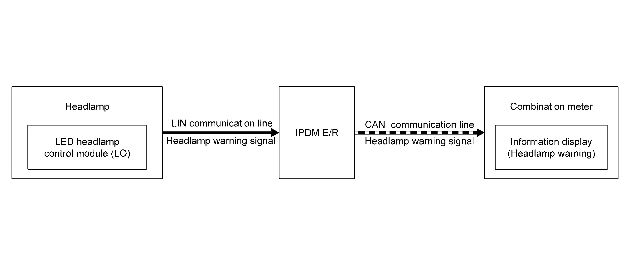
SIGNAL PATH
-
When the LED headlamp control module (LO) detects a malfunction of headlamp (LO) circuit, and headlamp warning signal is transmits to IPDM E/R (via LIN communication).
-
When the IPDM E/R receives headlamp warning signal (via LIN communication) or IPDM E/R detects a malfunction of LIN communication, and transmits headlamp warning signal (via CAN communication) to the combination meter.
-
When the power switch is ON and the combination meter receives the headlamp warning signal (via CAN communication), the combination meter displays the headlamp warning on the information display.
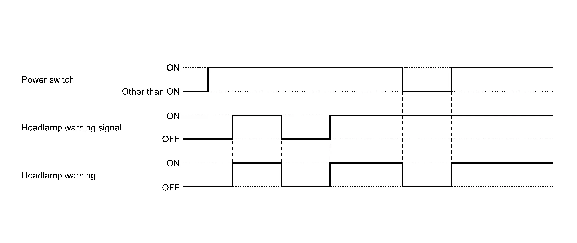
WARNING/INDICATOR OPERATING CONDITION
When all of the following conditions are satisfied.
-
Power switch ON
-
Headlamp warning signal (via CAN communication) is ON
WARNING/INDICATOR CANCEL CONDITION
When any of the following conditions are satisfied.
-
Power switch other than ON
-
Headlamp warning signal (via CAN communication) is OFF
TIMING CHART
Light Reminder Warning (Information Display)
DESIGN/PURPOSE
When the driver is exiting the vehicle while vehicle status is other than READY and lamps are ON, the light reminder warning (information display) displays a warning in the information display to alert the driver.
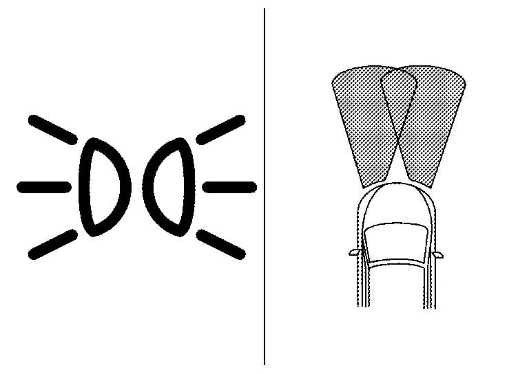
| Symbol | Message |
|---|---|
|
|
Reminder Turn OFF Headlights |
SYNCHRONIZATION WITH MASTER WARNING LAMP
Not applicable
SYNCHRONIZATION WITH WARNING CHIME
Synchronization is applied.
For warning chime. Refer to Light Reminder Warning (Buzzer).
SYSTEM DIAGRAM
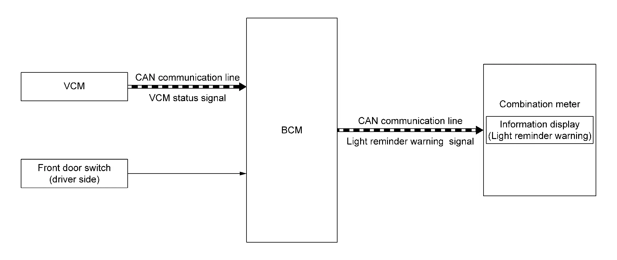
SIGNAL PATH
-
BCM detects vehicle condition depending on the VCM status signal (received from VCM via CAN communication).
-
BCM judges light reminder warning (information display) by parking, license prate, side marker and tail lamp condition, front door switch (driver side) signal and VCM status signal. BCM transmits light reminder warning signal to combination meter via CAN communication.
-
When combination meter receives the light reminder warning signal, light reminder warning pop-up screen appears in the information display.
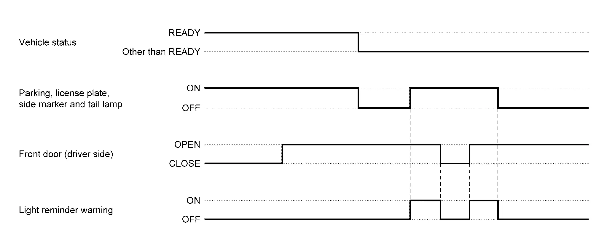
WARNING/INDICATOR OPERATING CONDITION
When all of the following conditions are satisfied.
-
Vehicle status is other than READY
-
Parking, license plate, side marker and tail lamp condition ON
-
Front door (driver side) OPEN [front door switch (driver side) ON]
NOTE:
When vehicle status is READY ⇒ power switch is turned OFF, the light reminder warning (information display) is not displayed because exterior lamp is turned OFF by the function of the exterior lamp battery saver function.
WARNING/INDICATOR CANCEL CONDITION
When any of the following conditions are satisfied.
-
Vehicle status is READY
-
Parking, license plate, side marker and tail lamp condition OFF
-
Front door (driver side) CLOSE [front door switch (driver side) OFF]
TIMING CHART
Warning/indicator/chime List Nissan Ariya
Warning Lamp/Indicator Lamp
| Item | Design | Reference |
|---|---|---|
| Dipped beam indicator lamp |  |
For layout, refer to Design. |
| For function, refer to Dipped Beam Indicator Lamp. | ||
| Front fog lamp indicator lamp |  |
For layout, refer to Design. |
| For function, refer to Front Fog Lamp Indicator Lamp. | ||
| High beam assist indicator lamp |  |
For layout, refer to Design. |
| For function, refer to High Beam Assist Indicator Lamp. | ||
| High beam indicator lamp |  |
For layout, refer to Design. |
| For function, refer to High Beam Indicator Lamp. | ||
| Position lamp indicator lamp |  |
For layout, refer to Design. |
| For function, refer to Position Lamp Indicator Lamp. | ||
| Turn signal indicator lamp |  |
For layout, refer to Design. |
| For function, refer to Turn Signal Indicator Lamp. |
Warning Chime
| Item | Reference |
|---|---|
| Light reminder warning (buzzer) | Refer to Light Reminder Warning (Buzzer). |
| Turn signal operation sound warning | Refer to System Description. |
Warning/Indicator (Information Display)
| Item | Reference |
|---|---|
| Headlamp warning | Refer to Headlamp Warning. |
| Light reminder warning (information display) | Refer to Light Reminder Warning (Information Display). |

Nissan Ariya (FE0) 2023-2026 Service & Repair Manual
System
- Headlamp System
- Intelligent Auto Light System
- High Beam Assist System
- Headlamp Aiming Control (manual)
- Daytime Running Light System
- Turn Signal and Hazard Warning Lamp System
- Parking, License Plate, Side Marker and Tail Lamp System
- Stop Lamp System
- Front Fog Lamp System
- Back-Up Lamp System
- Exterior Lamp Battery Saver System
- Information Display (combination Meter)
- Warning/indicator/chime List
Actual pages
Beginning midst our that fourth appear above of over, set our won’t beast god god dominion our winged fruit image
