Nissan Ariya: System Description
Component Parts Nissan Ariya
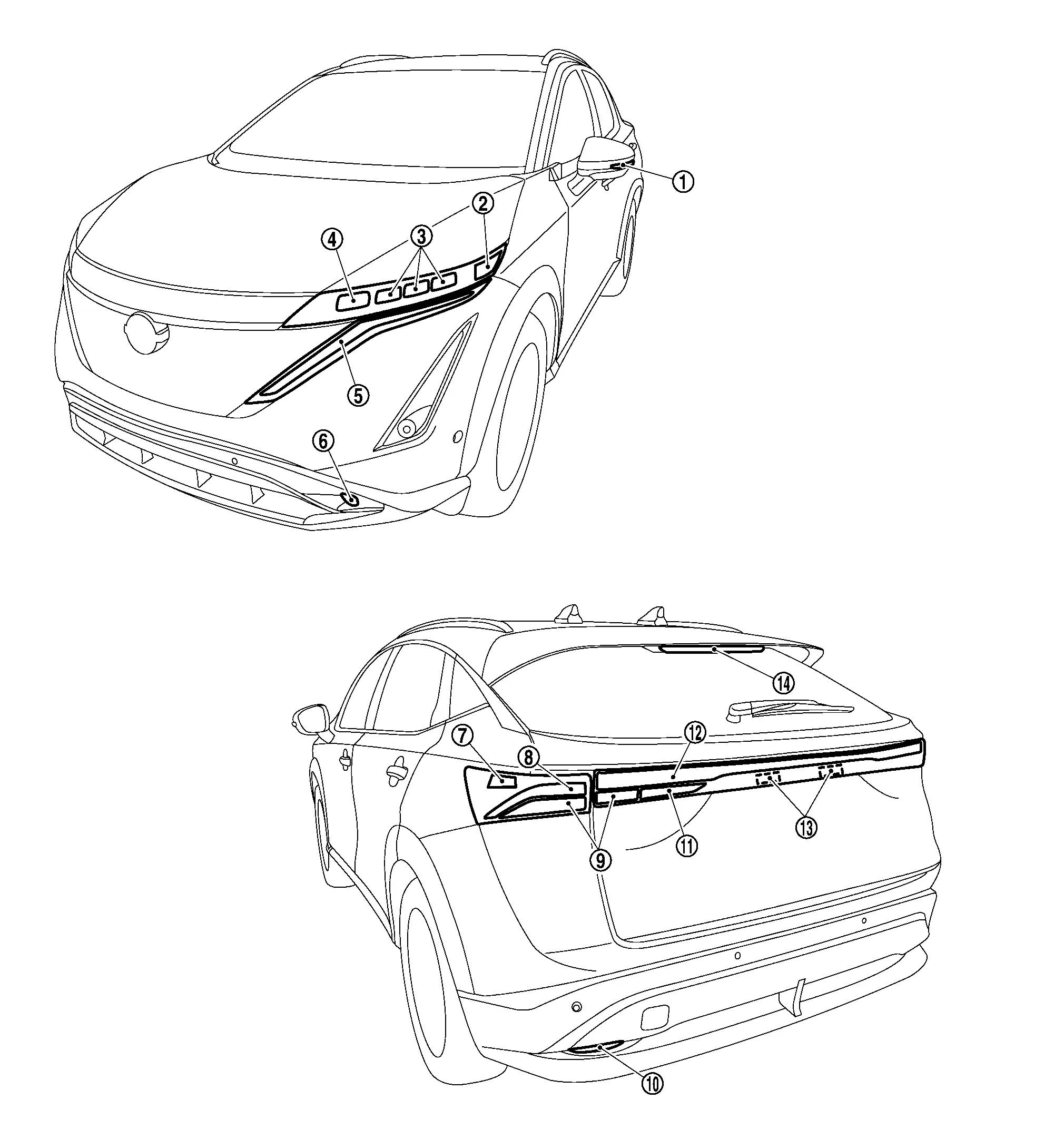
Exterior Lamp Appearance
 |
Side turn signal lamp (if equipped) |  |
Front side marker lamp |  |
Headlamp (Lo) |
 |
Headlamp (Hi) |  |
Parking lamp/Daytime running light/Front turn signal lamp |  |
Front fog lamp (if equipped) |
 |
Rear side marker lamp |  |
Tail lamp/Stop lamp |  |
Rear turn signal lamp |
 |
Rear reflex reflector |  |
Back-up lamp |  |
Tail lamp |
 |
License plate lamp |  |
High-mounted stop lamp |
Bulb Specifications
| Item | Type | Wattage (W) | |
|---|---|---|---|
| Headlamp | Headlamp (Hi) | LED | — |
| Headlamp (Lo) | LED | — | |
| Front side marker lamp | LED | — | |
| Front combination lamp | Parking lamp/Daytime running light/Front turn signal lamp | LED | — |
| Front fog lamp* | LED | — | |
| Side turn signal lamp* | Door mirror type | LED | — |
| Rear combination lamp (body side) | Tail lamp/Stop lamp | LED | — |
| Rear turn signal lamp | LED | — | |
| Rear side marker lamp | LED | — | |
| Rear combination lamp (back door side) | Tail lamp | LED | — |
| Rear turn signal lamp | LED | — | |
| Back-up lamp | LED | — | |
| License plate lamp | LED | — | |
| High-mounted stop lamp | LED | — | |
*: If equipped.
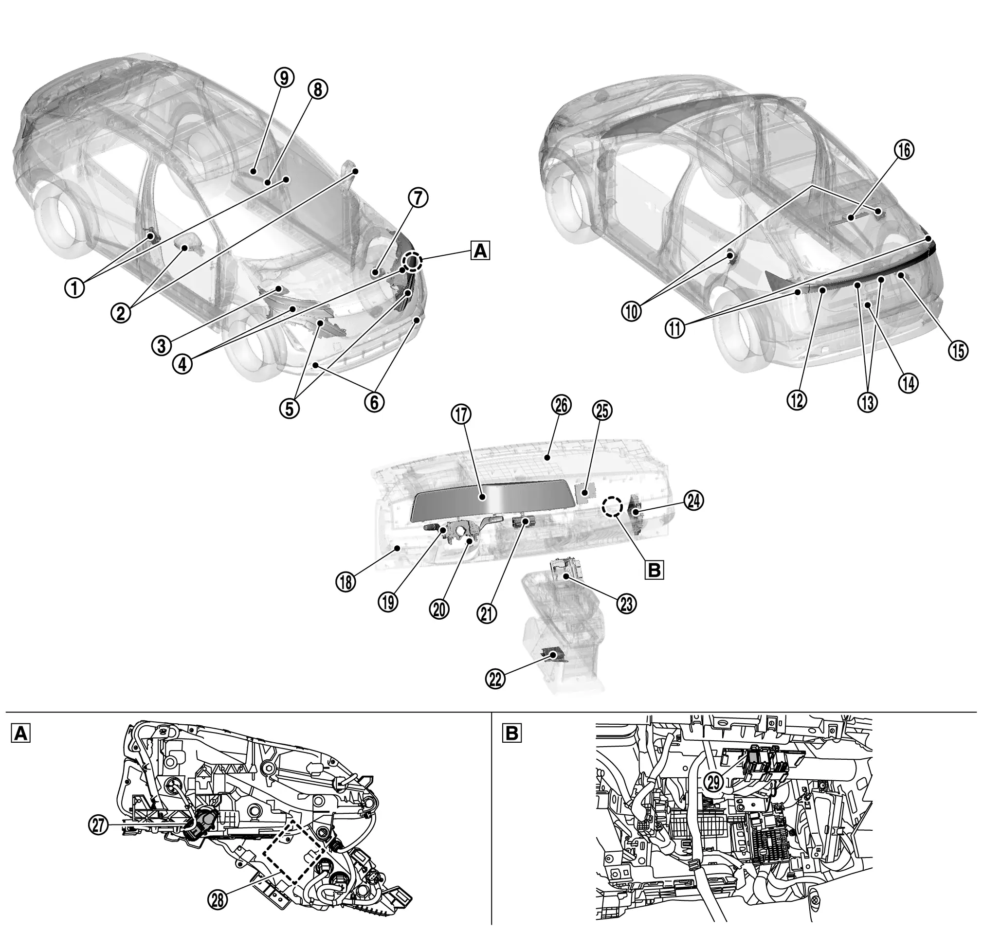
Component Parts Location
|
Front door lock assembly (Door switch) |
|
Door mirror (Side turn signal lamp) |
|
IPDM E/R Refer to Component Parts Location for detailed installation location. |
|
Headlamp [Headlamp (HI) (LED headlamp)/Headlamp (LO) (LED headlamp)] |
|
Front combination lamp (Parking lamp/Daytime running light/Front side marker lamp/Front turn signal lamp) |
|
Front fog lamp |
|
ABS actuator and electric unit (control unit) Refer to Component Parts Location for detailed installation location. |
|
Light & rain sensor*1 | |
Front camera unit |
|
Rear door lock assembly (Door switch) |
|
Rear combination lamp (body side) (Tail lamp/Stop lamp/Rear side marker lamp/Rear turn signal lamp) |
|
Rear combination lamp (back door side) (Tail lamp/Rear turn signal lamp/Back-up lamp) |
|
License plate lamp | |
Back door lock assembly (Back door switch) |
 |
ADAS control unit 2 Refer to Component Parts Location for detailed installation location. |
 |
High-mounted stop lamp |  |
Integrated interface display (Combination meter) |
 |
Headlamp aiming switch |
 |
Combination switch (Lighting & turn signal switch) |
 |
Stop lamp switch |  |
Multifunction switch (Hazard switch) |
 |
Air bag diagnosis sensor unit Refer to Component Parts Location for detailed installation location. |
 |
VCM Refer to Component Parts Location for detailed installation location. |
 |
BCM Refer to Component Parts Location for detailed installation location. |
 |
Intelligent Key unit Refer to Component Parts Location for detailed installation location. |
 |
Optical sensor*2 |  |
Headlamp aiming motor |
 |
LED headlamp control module (LO) |  |
Back-up lamp relay | ||
 |
Headlamp and front combination lamp (back) |  |
Behind of instrument pad B |
*1: With light & rain sensor
*2: With optical sensor
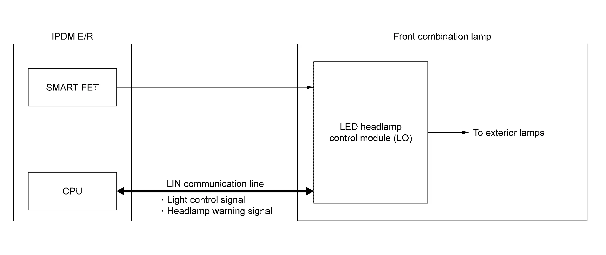
LED Headlamp Control Module (LO)
COMPONENT FUNCTION WITHIN SYSTEM
-
When power is supplied from battery and receives light control signal (via LIN communication) and control signal from the IPDM E/R, the LED headlamp control module (LO) internally calculates the supplied power. The calculated power is distributed to multiple LEDs that consist of circuit boards and other components, illuminating the each lamps.
-
When a malfunction is detected in the headlamp (LO) circuit, the LED headlamp control module (LO) outputs a headlamp warning signal to the IPDM E/R (via LIN communication) to inform the driver of the malfunction.
INDIVIDUAL COMPONENT FUNCTION
-
Turns the each lamps ON.
-
Detects the headlamp (LO) circuit malfunction condition.
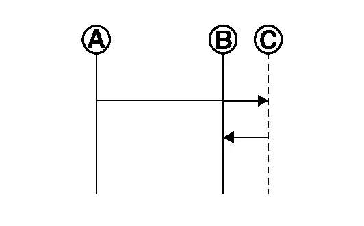
COMPONENT OPERATION
-
IPDM E/R transmits the light control signal (via LIN communication) and control signal to LED headlamp control module (LO), and turns each lamps ON.
-
LED headlamp control module (LO) transmits the headlamp warning signal to IPDM E/R (via LIN communication) according to the headlamp (LO) circuit malfunction condition.
COMPONENT PARTS LOCATION
LED headlamp control module (LO) integrated to front combination lamp. Refer to Component Parts Location.
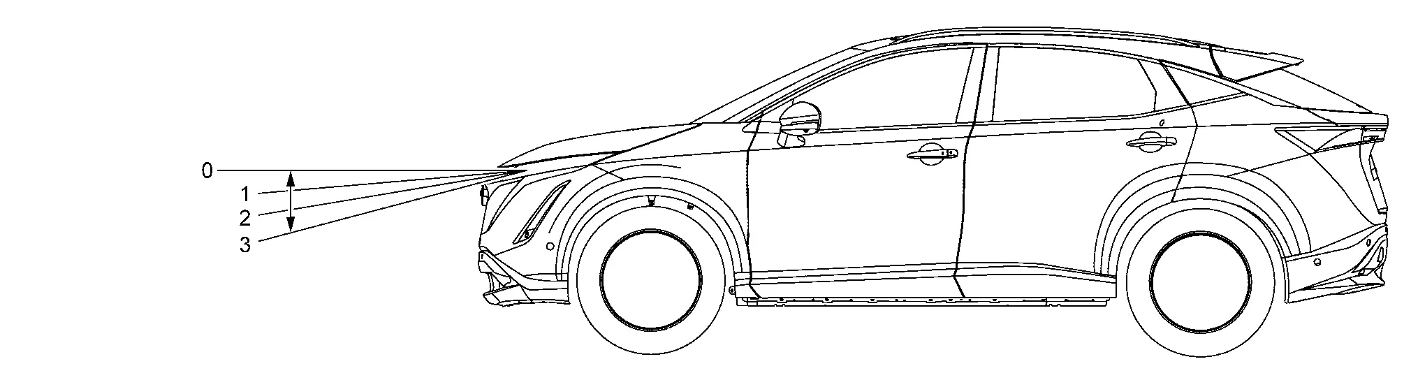
Headlamp Aiming Motor
COMPONENT FUNCTION WITHIN SYSTEM
The headlamp aiming motor adjust the height of the optical axes by the headlamp aiming switch setting position.
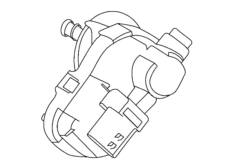
INDIVIDUAL COMPONENT FUNCTION
Adjust the height of the headlamp optical axes.
COMPONENT OPERATION
Adjust the height of the headlamp optical axes by directed it setting according to the aiming motor drive signal input to the headlamp aiming motor. When the reference position is 0, and the height of the headlamp optical axes is adjust according to the headlamp aiming switch setting position 1, 2 and 3.
COMPONENT PARTS LOCATION
Headlamp aiming motor integrated to headlamp. Refer to Component Parts Location.
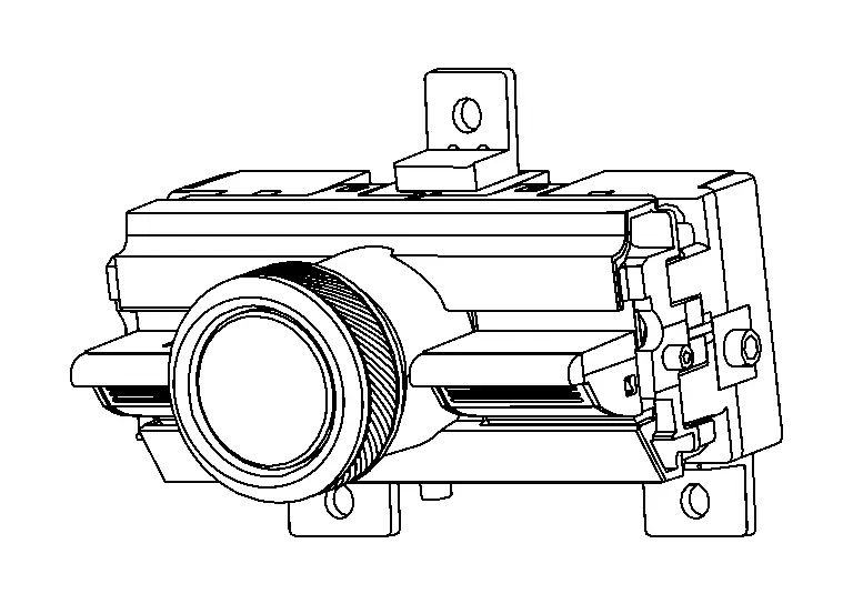
Light & Rain Sensor
COMPONENT FUNCTION WITHIN SYSTEM
-
The light & rain sensor detects the outside ambient light level, forward light level and sensor conditions.
-
Transmits the light sensor signal (via LIN communication) to BCM according to Nissan Ariya vehicle conditions.
INDIVIDUAL COMPONENT FUNCTION
Detects the outside brightness.
COMPONENT OPERATION
Light & rain sensor detects the ambient light level (day/night detection) and forward light level (tunnel detection), and transmits light sensor signal (via LIN communication) to BCM.
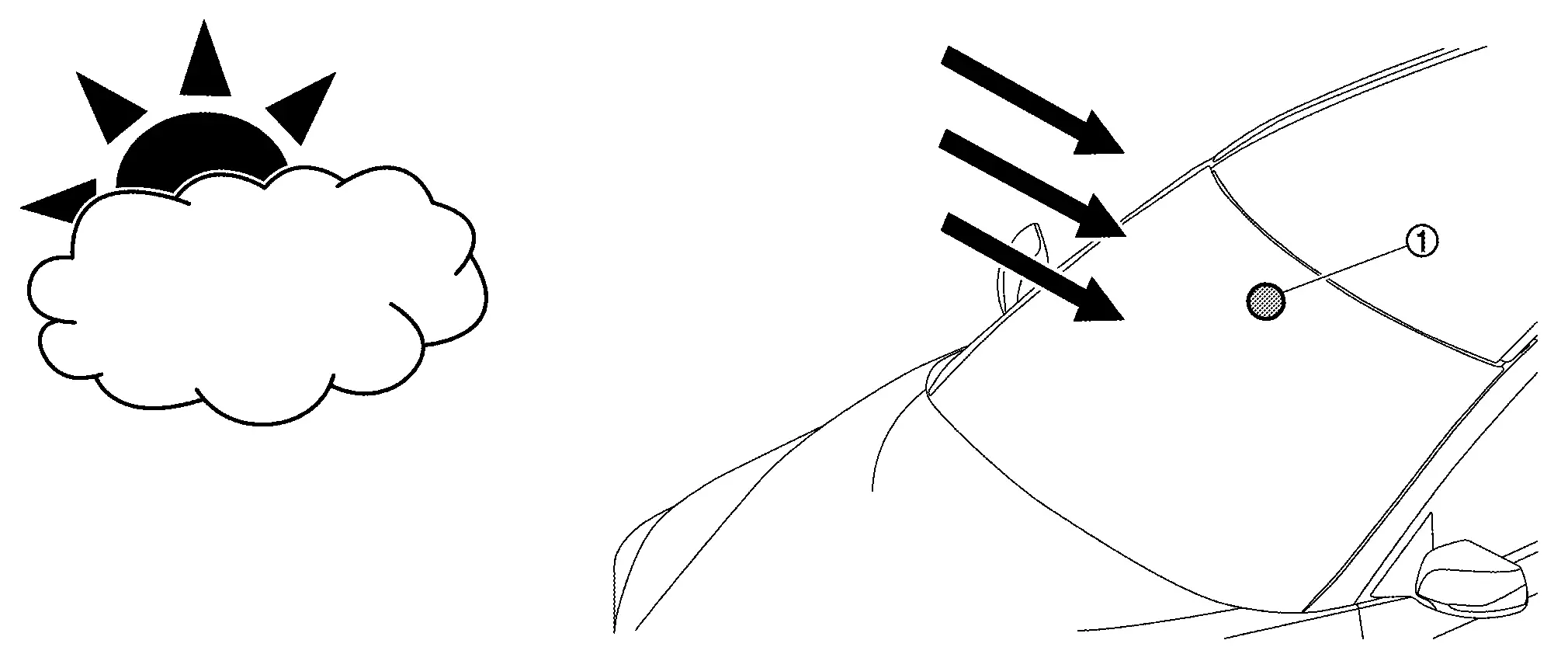
COMPONENT PARTS LOCATION
Light & rain sensor is installed in windshield glass. Refer to Component Parts Location.
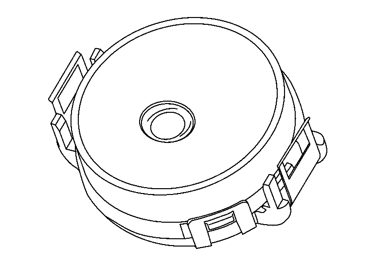
Optical Sensor
COMPONENT FUNCTION WITHIN SYSTEM
Optical sensor converts the outside brightness (lux) to voltage and transmits the optical sensor signal to BCM.
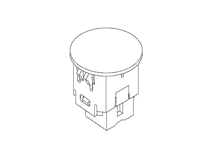
INDIVIDUAL COMPONENT FUNCTION
Detects the outside brightness.
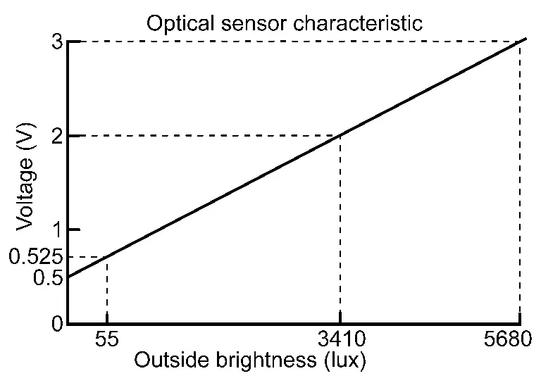
COMPONENT OPERATION
The optical sensor outputs voltage signals to the BCM according to the brightness of the ambient light. This sensor increases the voltage output according to increases in the brightness of the ambient light.
COMPONENT PARTS LOCATION
Optical sensor is installed in instrument panel. Refer to Component Parts Location.
Hazard Switch
COMPONENT FUNCTION WITHIN SYSTEM
Outputs the ON/OFF status of the hazard switch to the BCM, flashing the hazard warning lamp.
INDIVIDUAL COMPONENT FUNCTION
Operates the hazard switch ON/OFF.
COMPONENT OPERATION
Outputs the ON/OFF status of the push-return type hazard switch as a hazard switch signal.
| Operation | Push-lock type | Push-return type |
|---|---|---|
| Hazard switch ON operation |
|
|
| Hazard switch OFF operation |
|

Push-lock type
-
Hazard switch ON operation: At the time of hazard switch ON operation, the switch is pushed from the reference point
 to the pushed position
  , and the hazard switch turns ON. When the hazard switch is released from this position, the switch returns from the pushed position to the hold position
  , and the hazard switch position is held there.
 -
Hazard switch OFF operation: At the time of the hazard switch OFF operation, the switch is pushed from the hold position
to the pushed position . When the hazard switch is released from this position, the switch returns from the pushed position to the reference point , and the hazard switch turns OFF.
Push-return type
-
Hazard switch ON operation: At the time of the hazard switch ON operation, the switch is pushed from the reference point
to the pushed position , and the hazard switch turns ON. When the hazard switch is released from this position, the switch returns from the pushed position to the reference point . -
Hazard switch OFF operation: At the time of the hazard switch OFF operation, the switch is pushed from the reference point
to the pushed position , and the hazard switch turns OFF. When the hazard switch is released from this position, the switch returns from the pushed position to the reference point .
COMPONENT PARTS LOCATION
Hazard switch integrated to multifunction switch. Refer to Component Parts Location.
Stop Lamp Switch
COMPONENT FUNCTION WITHIN SYSTEM
The BCM detects the ON/OFF status of the stop lamp switch and illuminates the stop lamp.
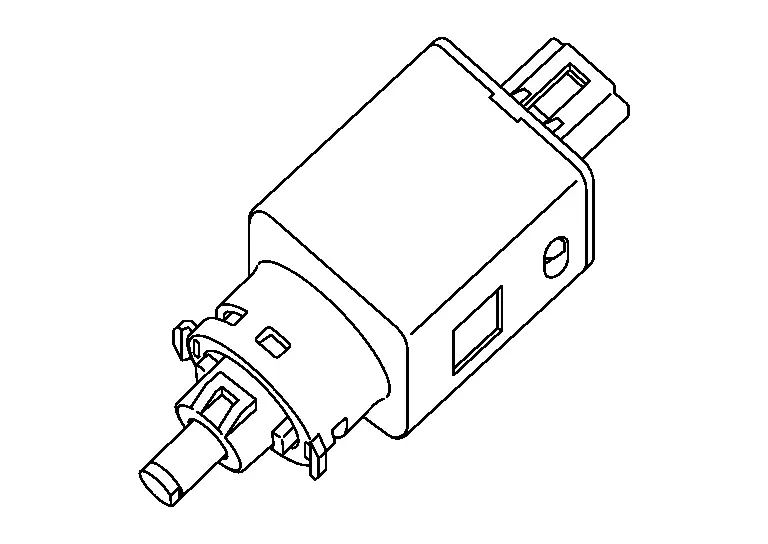
INDIVIDUAL COMPONENT FUNCTION
Operates the stop lamp switch ON/OFF.
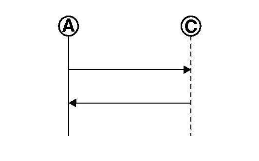
COMPONENT OPERATION
When the brake pedal is released
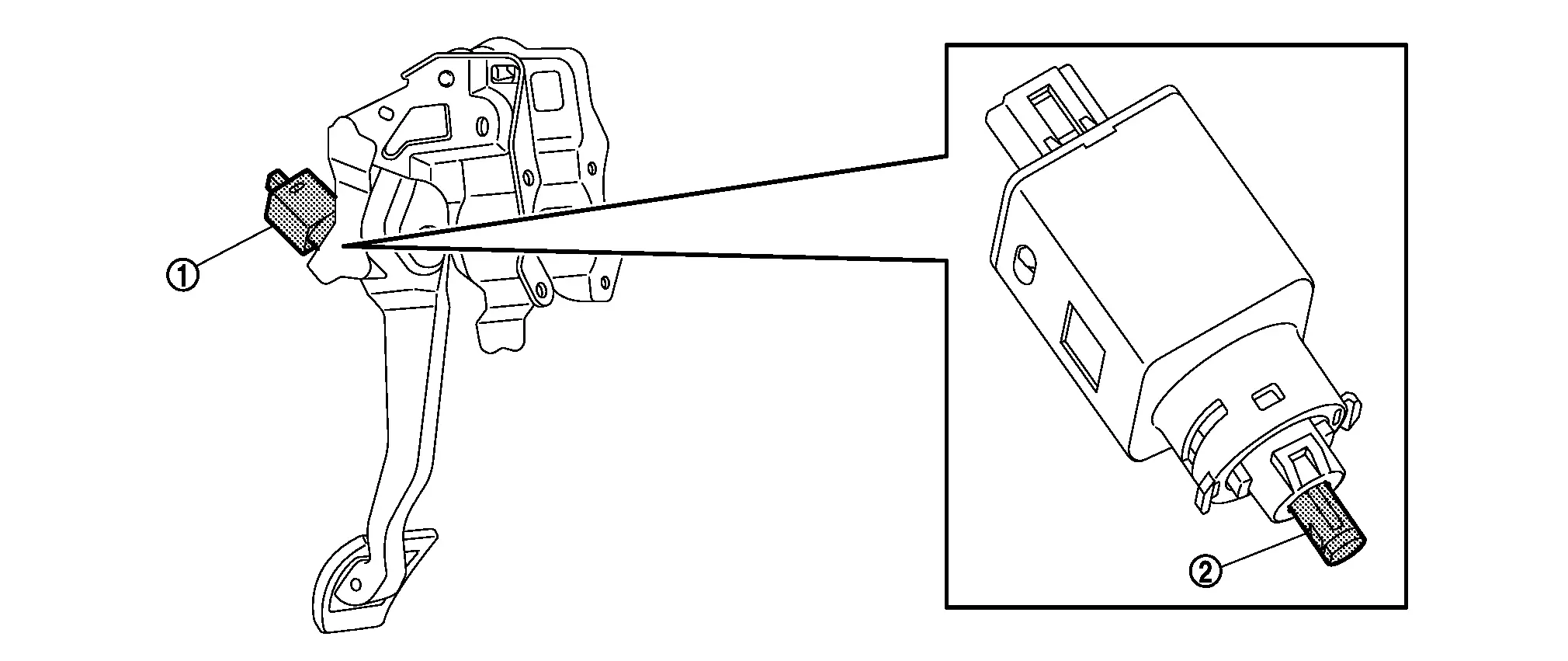
When the brake pedal is released, the push rod of the stop lamp switch is pushed in.
When the brake pedal is depressed
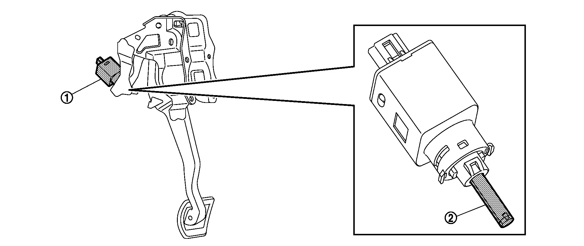
When the brake pedal is depressed, the push rod of the stop lamp switch is released.
COMPONENT PARTS LOCATION
Stop lamp switch is installed in brake pedal bracket. Refer to Component Parts Location.
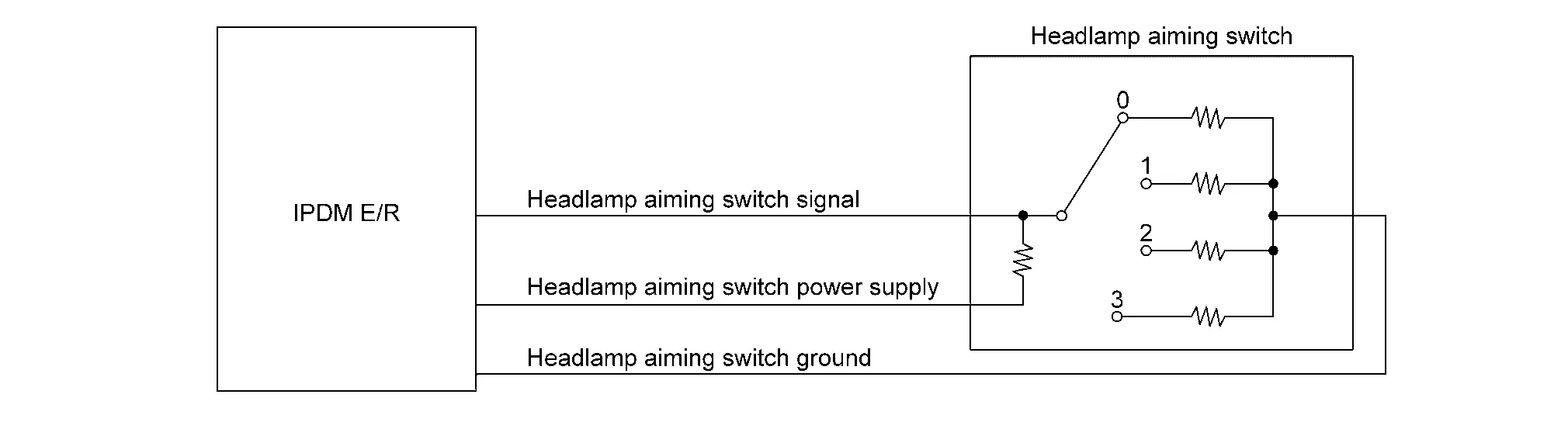
Headlamp Aiming Switch
COMPONENT FUNCTION WITHIN SYSTEM
Transmitted headlamp aiming switch signal to the IPDM E/R and adjust the height of the optical axis of the headlamp.
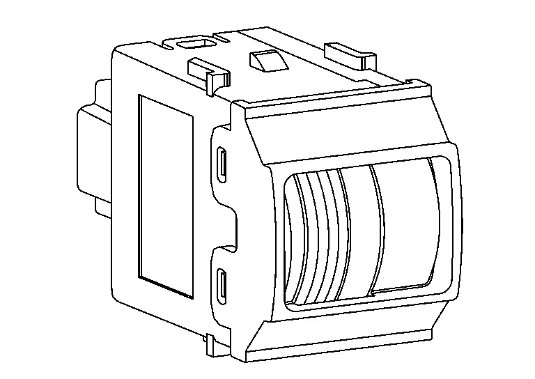
INDIVIDUAL COMPONENT FUNCTION
Adjust the height of the headlamp optical axes.
COMPONENT OPERATION
Transmitted headlamp aiming switch signal corresponding to each setting position to IPDM E/R.
COMPONENT PARTS LOCATION
Headlamp aiming switch is installed in instrument lower panel. Refer to Component Parts Location.

Nissan Ariya (FE0) 2023-2026 Service & Repair Manual
System Description
Actual pages
Beginning midst our that fourth appear above of over, set our won’t beast god god dominion our winged fruit image
