Nissan Ariya: Removal and Installation
- Front Wiper
- Front Wiper Arm
- Front Wiper Blade
- Front Wiper Refill
- Front Wiper Drive Assembly
- Rear Wiper
- Rear Wiper Arm
- Rear Wiper Blade
- Rear Wiper Motor
- Washer Tank
- Washer Pump
- Front Washer Nozzle and Tube
- Front Washer Nozzle
- Front Washer Tube
- Rear Washer Nozzle and Tube
- Rear Washer Nozzle
- Rear Washer Tube
- Light & Rain Sensor
- Wiper and Washer Switch
Front Wiper Nissan Ariya 2023
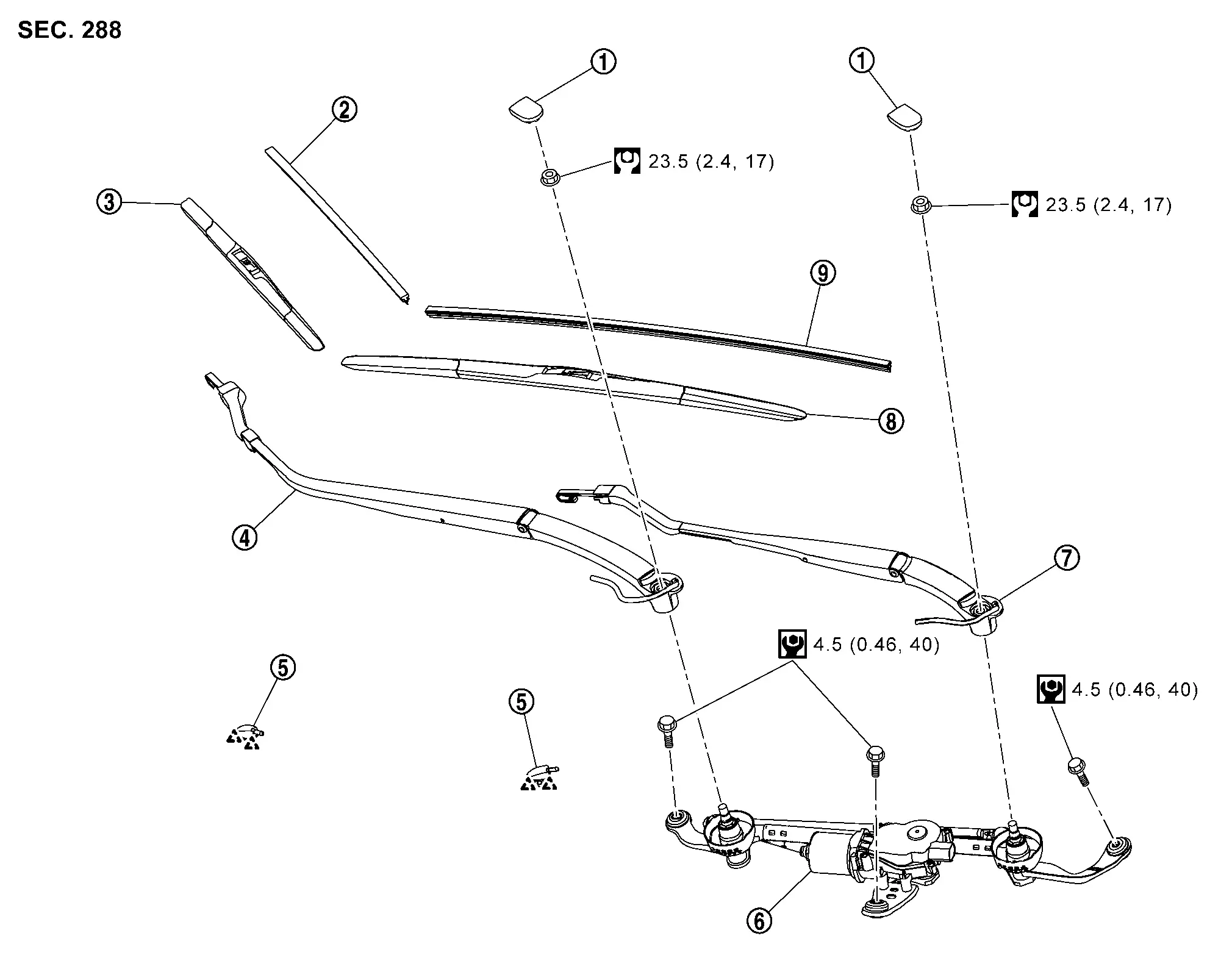
Exploded View
 |
Front wiper arm cover |  |
Front wiper refill RH |  |
Front wiper blade RH |
 |
Front wiper arm RH |  |
Tube connector |  |
Front wiper drive assembly |
 |
Front wiper arm LH |  |
Front wiper blade LH |  |
Front wiper refill LH |
 |
: N·m (kg-m, in-lb) | ||||
 |
: N·m (kg-m, ft-lb) | ||||
|
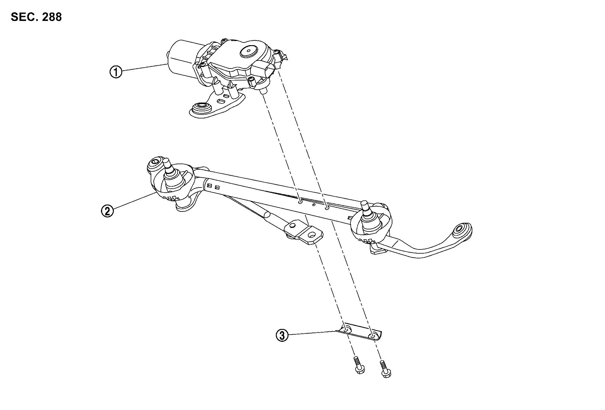
Front wiper drive | |
Front wiper linkage | |
Front wiper drive bracket |
Front Wiper Arm Nissan Ariya 1st generation
Removal & Installation
CAUTION:
Clean the windshield glass and front wiper refill so that the windshield glass may not be damaged by dust, etc.
REMOVAL
Operate front wiper to auto stop position. Refer to System Description.
Remove front wiper arm cover.
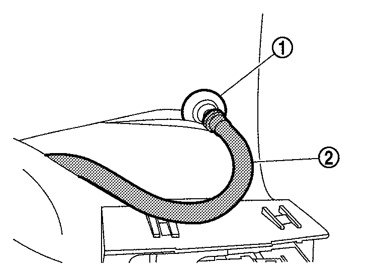
Disconnect front washer tube from tube connector .
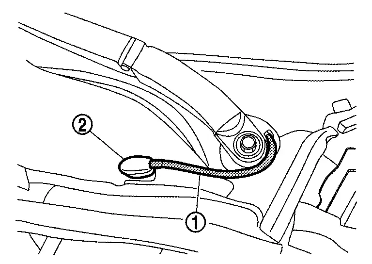
Remove front wiper arm mounting nut  .
.
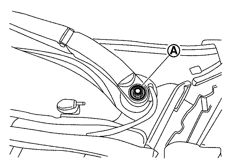
Remove front wiper arm.
INSTALLATION
Note the following items, and then install in the reverse order of removal.
CAUTION:
When installation front wiper arm, inspection the front washer nozzle spray position. Refer to Inspection.
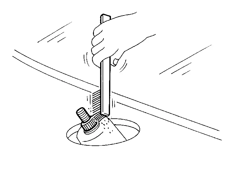
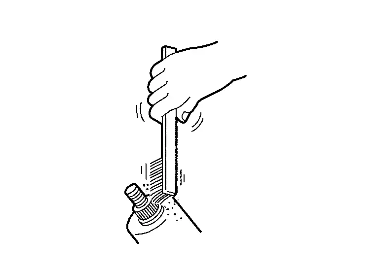
Clean front wiper arm mount as shown in the figure to prevent nuts from being loosened.
Operate front wiper drive assembly to auto stop position.
Install front wiper arm, and then adjust front wiper arm position. Refer to Adjustment.
Tighten front wiper arm mounting nut to the specified torque. For the specified torque, Refer to Exploded View.
Install front washer tube.
Spray washer fluid.
 NOTE:
NOTE:
Spray to avoid damaging the windshield glass.
Operate front wiper to auto stop position.
Check that the front wiper blade stop at the specified position. Refer to Adjustment
Install front wiper arm cover.
Adjustment
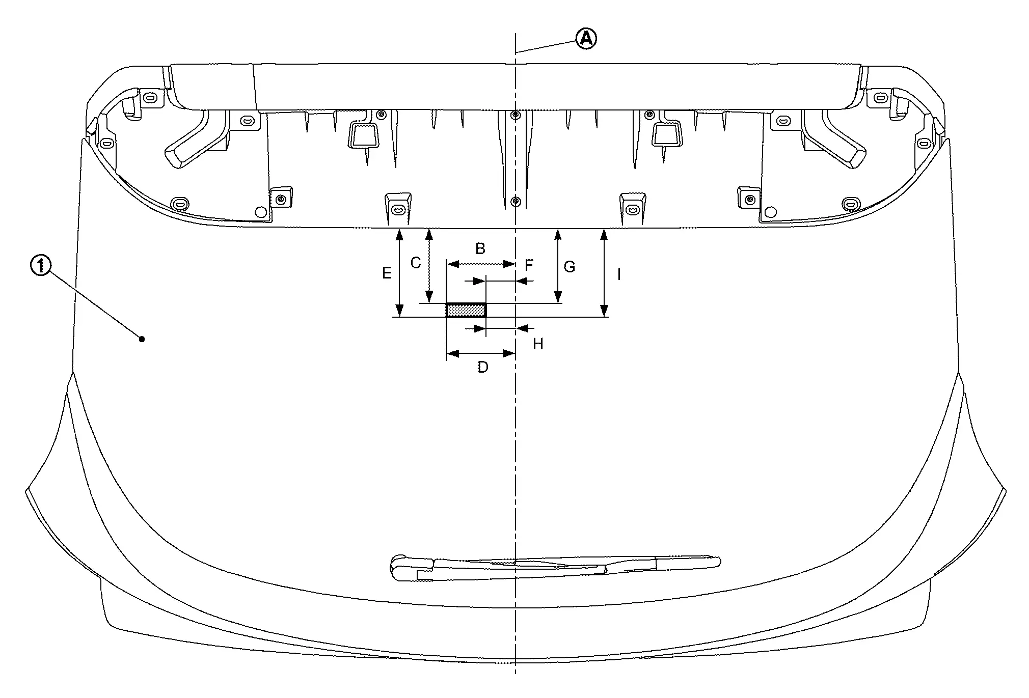
WIPER BLADE POSITION ADJUSTMENT
NOTE:
-
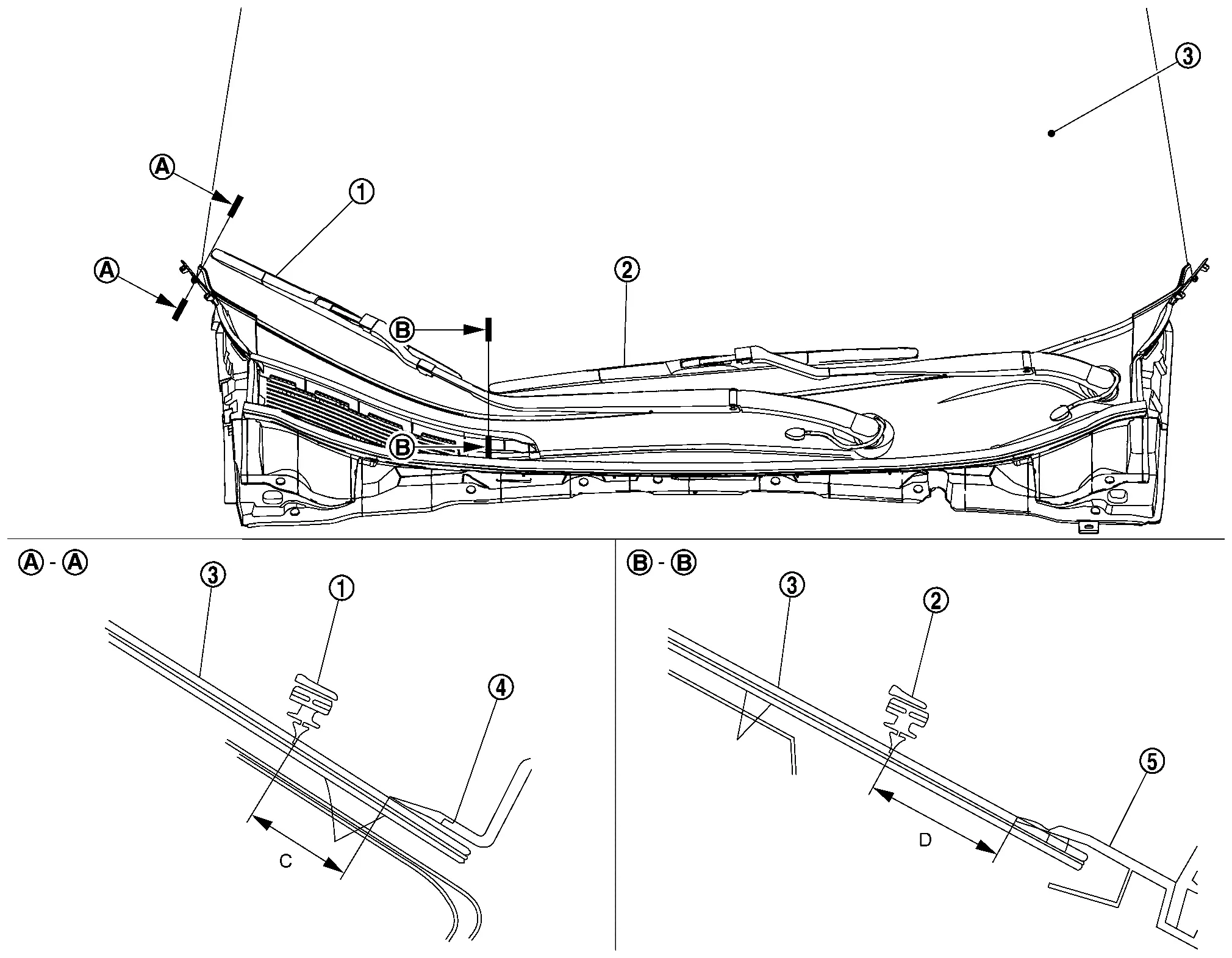
Clearance between the end of cowl top cover/front fender cover and the top of front wiper blade center.
-
Perform measurement of clearance to the vertical direction of wiper blade.
|
Front wiper blade RH | |
Front wiper blade LH | |
Windshield glass |
|
Fender cover RH | |
Cowl top cover |
| C | : 19.1 mm (± 7.5 mm) [0.75 in (±0.30 in)] |
| D | : 34.41 mm (± 7.5 mm) [1.35 in (±0.30 in)] |
Front Wiper Blade Nissan Ariya 2023
Removal & Installation
CAUTION:
Clean windshield glass and front wiper refill so that windshield glass may not be damaged by dust, etc.
REMOVAL
Operate front wiper to auto stop position. Refer to System Description.
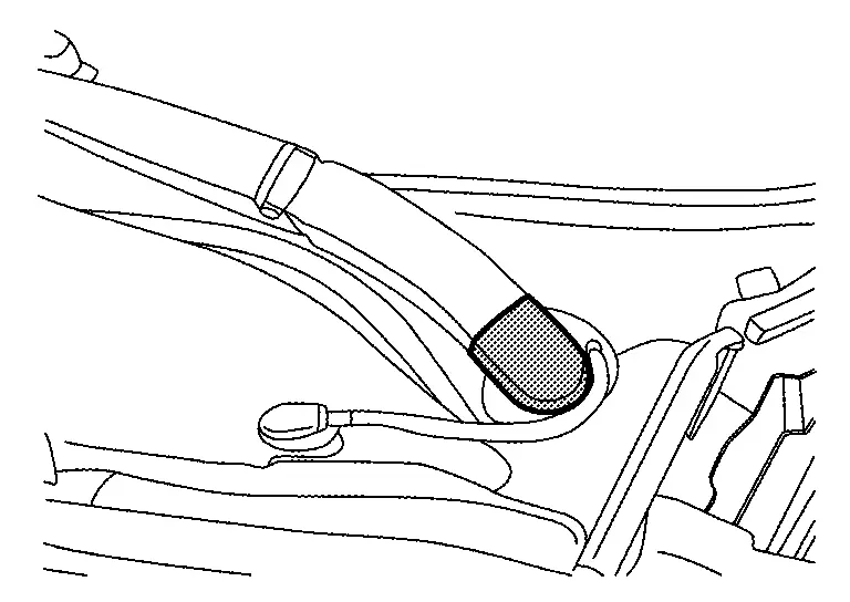
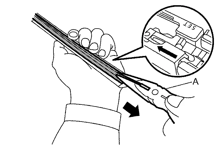
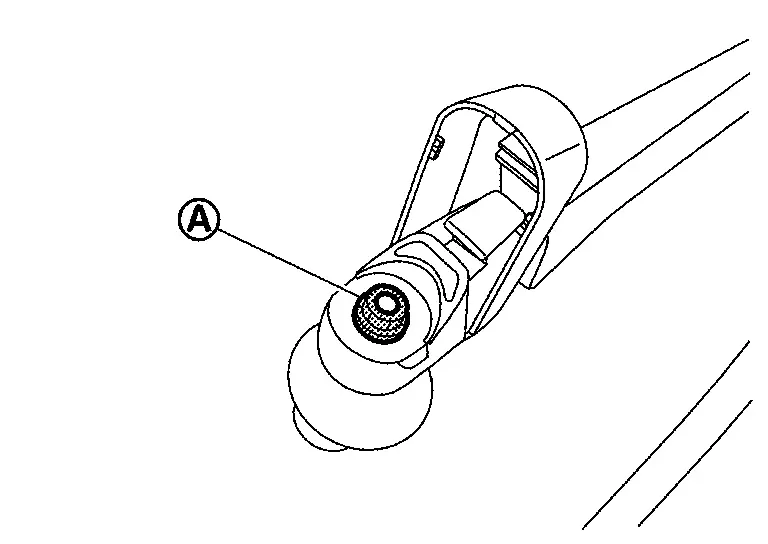
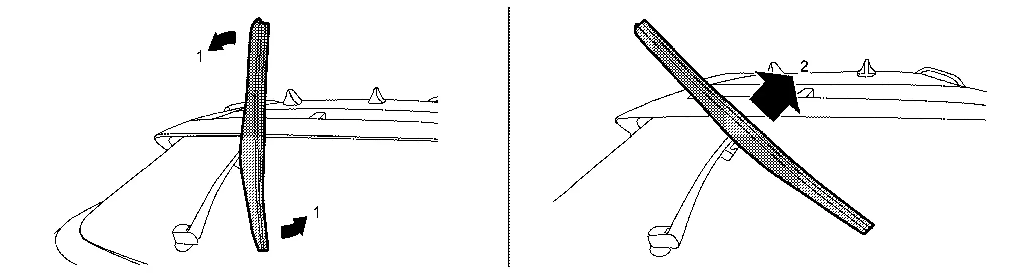
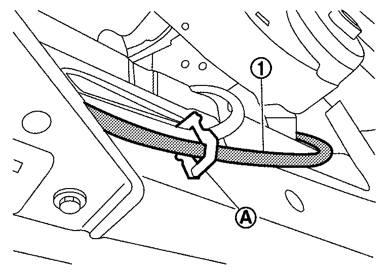
Lift up front wiper arm, and then lock back front wiper arm.
Unlock cover of front wiper blade using a remover tool (A) as shown by the arrow in the figure.
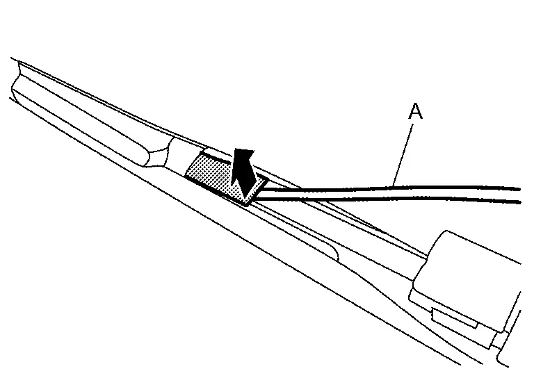
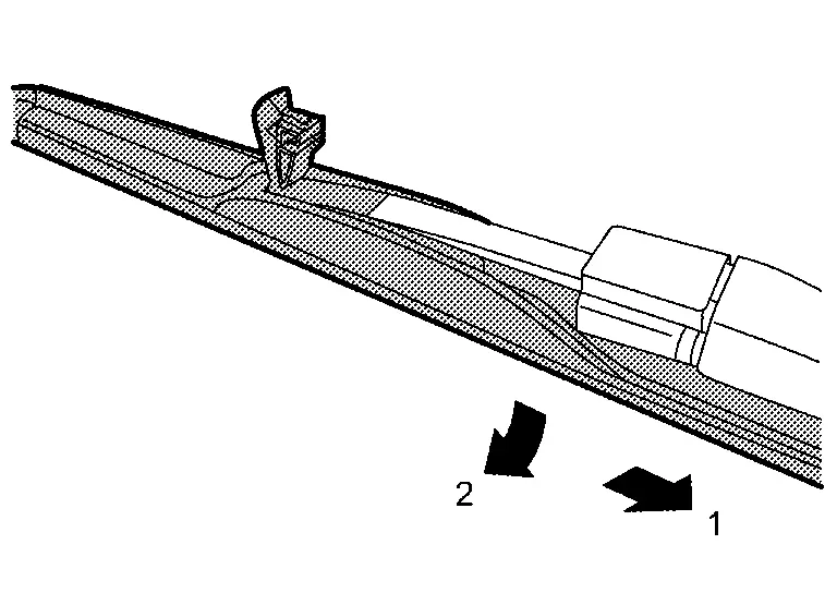
Slide wiper blade according to the numerical order 1→2 indicated by arrows as shown in the figure from front wiper arm, and then remove front wiper blade.
CAUTION:
After front wiper blade is removed, wrap front wiper arm with a shop cloth and fold it down so that front wiper arm does not fall against and damage windshield glass.
INSTALLATION
Install in the reverse order of removal.
Front Wiper Refill Nissan Ariya 1st generation
Removal & Installation
REMOVAL
Remove front wiper blade. Refer to Removal & Installation.
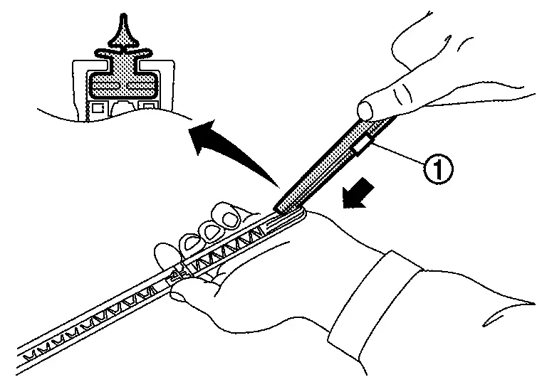
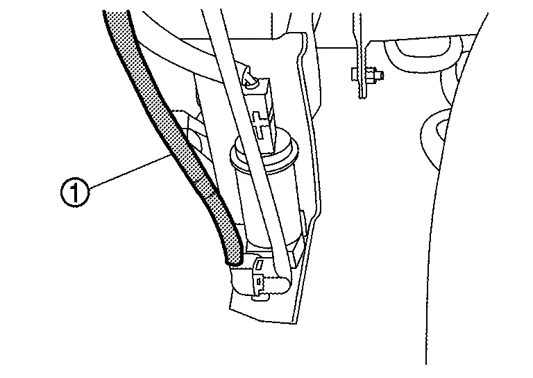
Pull out front wiper refill using a long-nose pliers (A), and then remove front wiper refill.
INSTALLATION
Check front wiper refill insertion direction by arrow mark on front wiper blade.
Pass through pawl of front wiper blade in groove of front wiper refill.
NOTE:
Remove holder * at last procedure.
*: Attached to service parts.
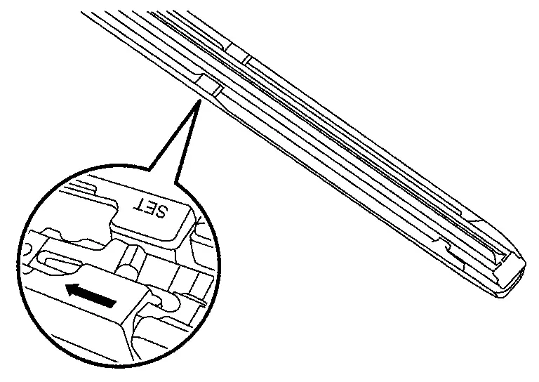
Engage front wiper refill stopper hole, and front wiper blade pawl with imprinted “SET” mark (“ ” mark).
Check the following items after installing.
-
Front wiper refill thoroughly fits in the pawl on front wiper blade.
-
Front wiper refill is not deformed (waving/tucking).
-
Front wiper refill is inserted from the proper direction.
NOTE:
When vertebra is detached on installation, note the following items, and then insert vertebra into front wiper blade.
-
Insert vertebra
into front wiper blade to the same bending direction.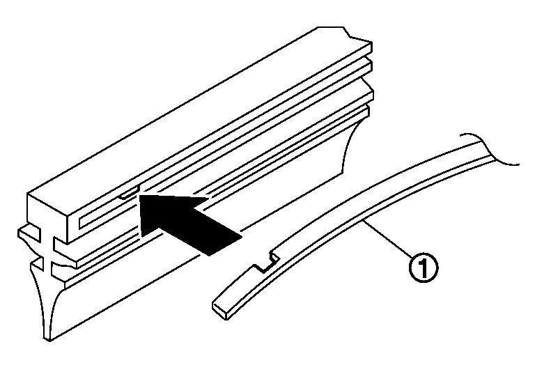
-
If a vertebra has a notch, fit it to a protrusion inside front wiper refill.
Front Wiper Drive Assembly Nissan Ariya 2026
Removal & Installation
REMOVAL
Remove cowl top cover. Refer to Removal & Installation.
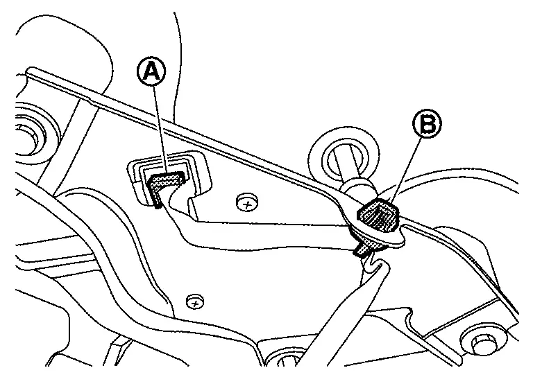
Remove front wiper drive assembly mounting bolts .
Disconnect front wiper motor harness connector and harness clip  .
.
Remove front wiper drive assembly.
INSTALLATION
Note the following items, and then install in the reverse order of removal.
CAUTION:
-
When installing, temporarily tighten all mounting bolts, and then tighten bolts to specified torque. Refer to Exploded View.
-
When front wiper drive assembly is replaced, before installing front wiper arm, operate front wipers, set front wiper motor to the auto stop position, and then install front wiper arms.
Disassembly & Assembly
DISASSEMBLY
Remove front wiper drive assembly. Refer to Removal & Installation.
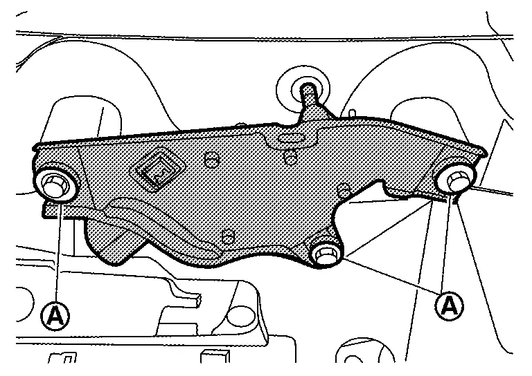
Remove front wiper drive mounting bolts, and then remove front wiper drive and front wiper drive bracket from front wiper linkage.
ASSEMBLY
Assembly in the reverse order of disassembly.
Rear Wiper Nissan Ariya
Exploded View
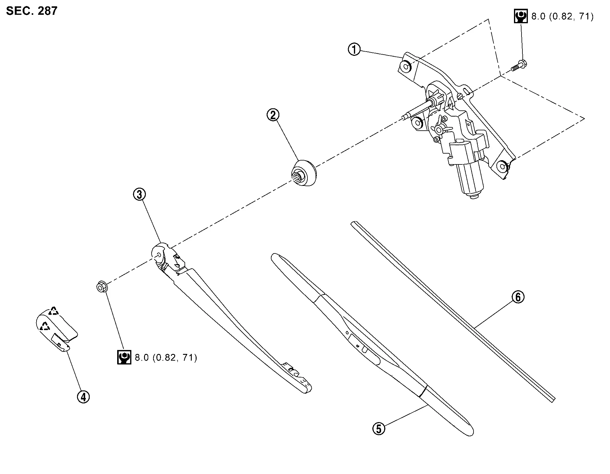
|
Rear wiper motor | |
Pivot seal | |
Rear wiper arm |
|
Rear wiper arm cover | |
Rear wiper blade | |
Rear wiper refill |
 |
: Pawl | ||||
|
: N·m (kg-m, in-lb) | ||||
Rear Wiper Arm Nissan Ariya 2023
Removal & Installation
CAUTION:
Clean back door window glass and rear wiper refill so that back door window glass may not be damaged by dust, etc.
REMOVAL
Operate rear wiper to auto stop position. Refer to System Description.
Disengage rear wiper arm cover fixing pawls, and then open rear wiper arm cover.
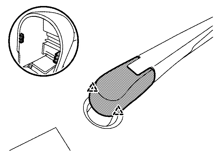
|
: Pawl |
Remove rear wiper arm mounting nut .
Pull up rear wiper arm, and then remove rear wiper arm.
INSTALLATION
Clean rear wiper arm installation location as shown in the figure, and then fully insert rear wiper arm to prevent nut from being loosened by shakiness.
Operate rear wiper motor to auto stop position.
Install rear wiper arm.
Tighten rear wiper arm mounting nut to the specified torque. For the specified torque, Refer to Exploded View.
Spray washer fluid.
NOTE:
Spray to avoid damaging the back door window glass.
Operate rear wiper to auto stop position.
Check that the rear wiper blade stop at the specified position. Refer to Adjustment.
Install rear wiper arm cover.
Adjustment
REAR WIPER ARM POSITION ADJUSTMENT
NOTE:
-
Perform measurement of clearance to the vertical direction of wiper blade.
-
Clearance between the end of back door window glass and the top of rear wiper blade center.
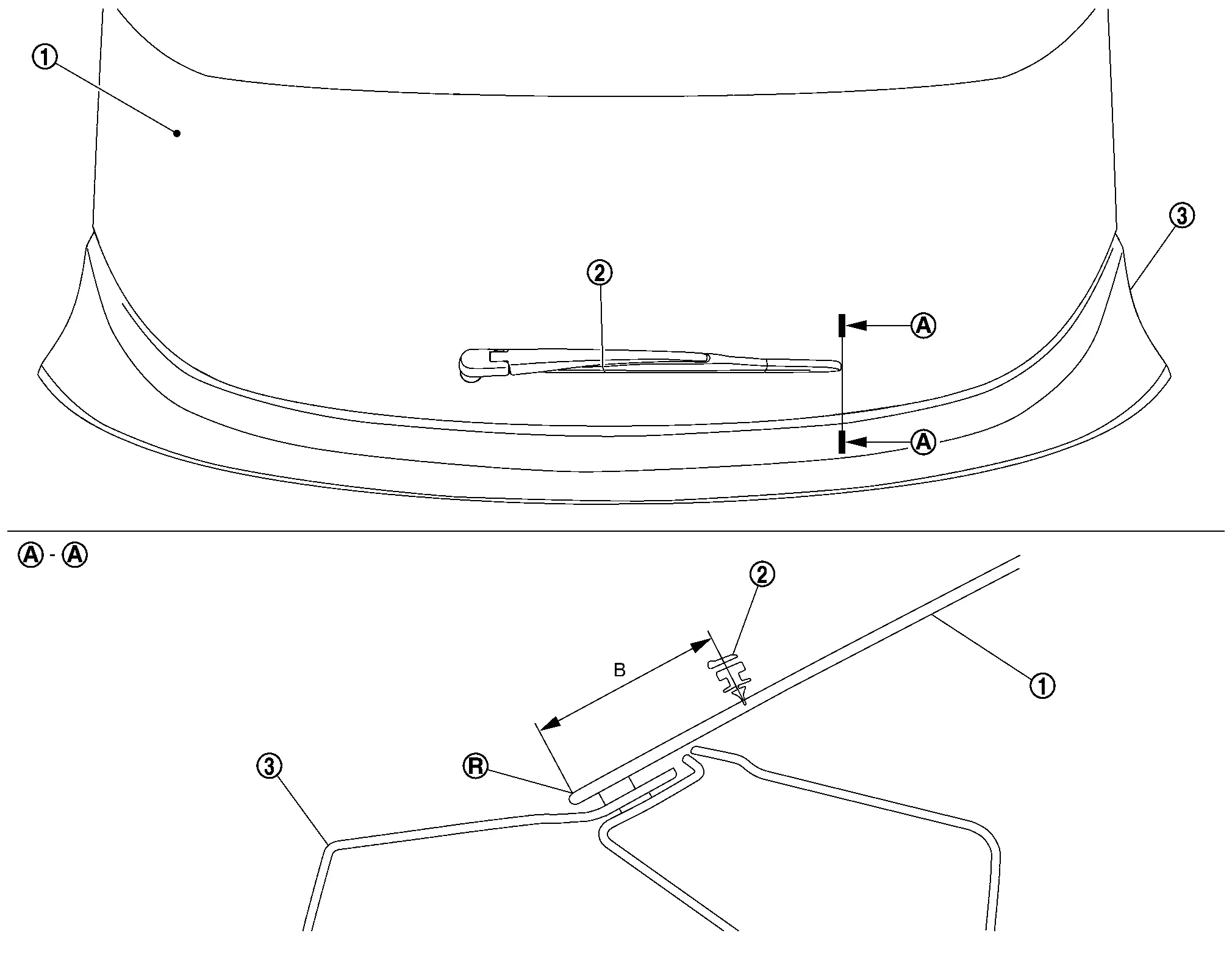
|
Back door window glass | |
Rear wiper blade | |
Back door panel |
 |
R end |
| B | : 58.1 mm (2.29 in) |
Rear Wiper Blade Nissan Ariya: FE0
Removal & Installation
REMOVAL
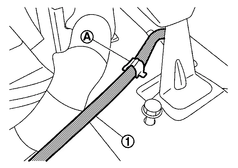
Lift up rear wiper arm, and then lock back rear wiper arm.
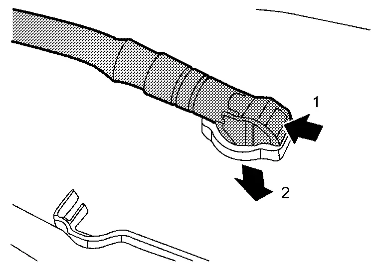
Remove rear wiper blade according to the numerical order 1→2 indicated by the arrows as shown in the figure.
CAUTION:
After rear wiper blade is removed, wrap rear wiper arm tip with a shop cloth and fold it down so that rear wiper arm does not fall against and damage back door window glass.
INSTALLATION
Install in the reverse order of removal.
Rear Wiper Motor Nissan Ariya 1st generation
Removal & Installation
REMOVAL
Remove rear wiper arm. Refer to Removal & Installation.
Remove back door inner finisher. Refer to Removal & Installation.
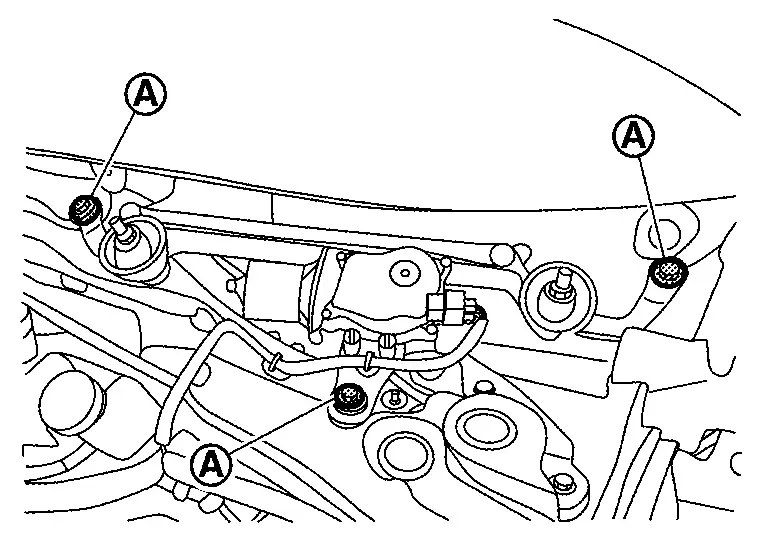
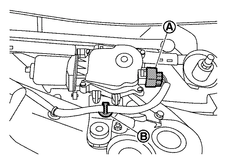
Disconnect rear wiper motor harness connector and fixing harness clip .
Remove rear wiper motor mounting bolts , and then remove rear wiper motor.
Remove pivot seal from back door window glass.
INSTALLATION
CAUTION:
-
When installing, temporarily tighten all mounting bolts, and then tighten bolts to specified torque. Refer to Exploded View.
-
When rear wiper drive motor is replaced, before installing rear wiper arm, operate rear wipers, set rear wiper motor to the auto stop position, and then install rear wiper arms.
Install pivot seal.
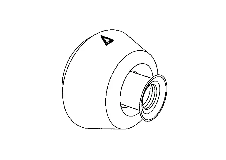
CAUTION:
-
When installing the pivot seal, check that "
 " mark faces toward the Nissan Ariya vehicle upper as shown in the figure.
 -
From the back door window glass inner side, also check that the pivot seal is securely installed to the back door window glass.
Install rear wiper motor.
Connect rear wiper motor harness connector and harness clip.
Operate rear wiper to auto stop position.
Install back door inner finisher. Refer to Removal & Installation
Install rear wiper arm. Refer to Removal & Installation
Washer Tank Nissan Ariya: FE0
Exploded View
Without Washer level switch
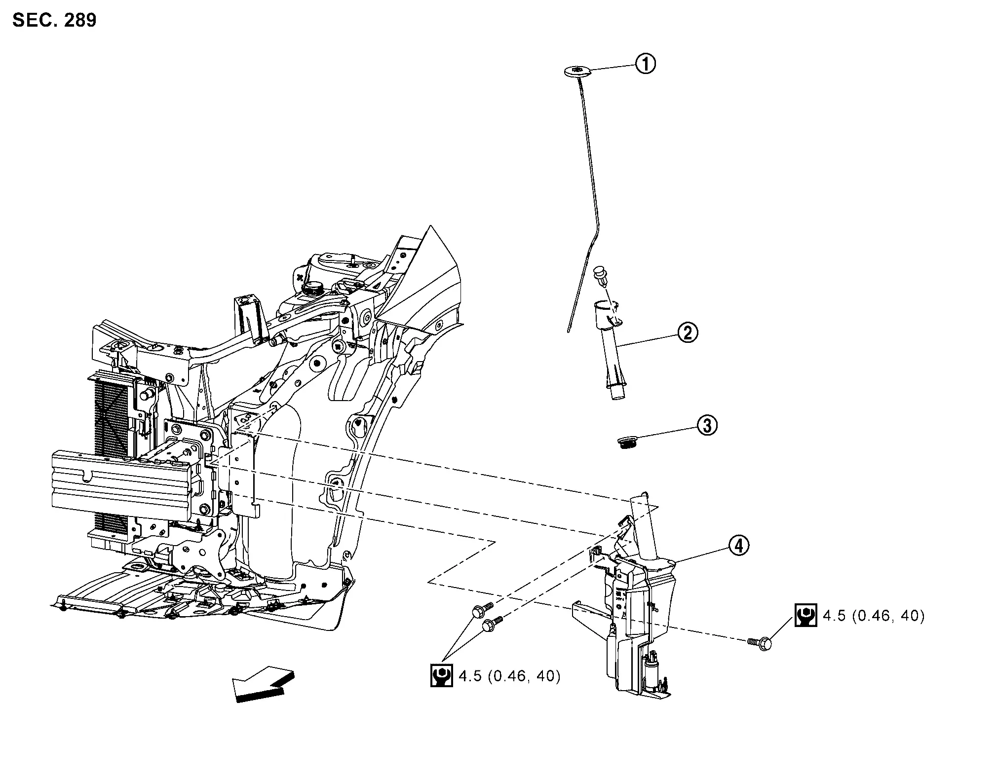
|
Washer tank cap | |
Washer tank inlet | |
Washer tank packing |
|
Washer tank | ||||
 |
: Nissan Ariya Vehicle front | ||||
|
: N·m (kg-m, in-lb) | ||||
With Washer level switch
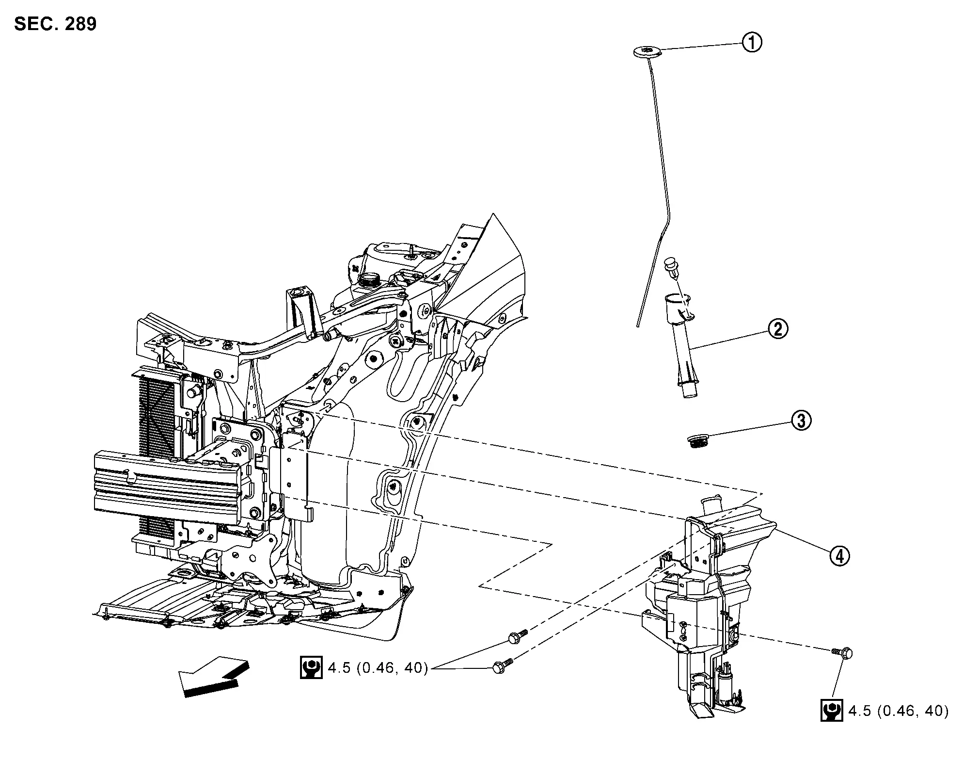
|
Washer tank cap | |
Washer tank inlet | |
Washer tank packing |
|
Washer tank | ||||
|
: Nissan Ariya Vehicle front | ||||
|
: N·m (kg-m, in-lb) | ||||
Removal & Installation
CAUTION:
When washer tank is removed, washer fluid may come out so prepare a container to receive the fluid and never allow fluid to be sprinkled.
REMOVAL
Fully open hood assembly.
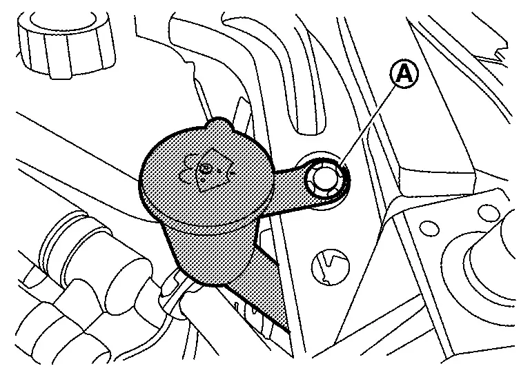
Remove washer tank inlet fixing clip , and then remove washer tank inlet.
Remove washer tank cap from washer tank inlet.
Remove front bumper fascia assembly. Refer to Removal & Installation.
Disconnect washer pump harness connector , and then remove front washer tube A and rear washer tube A .
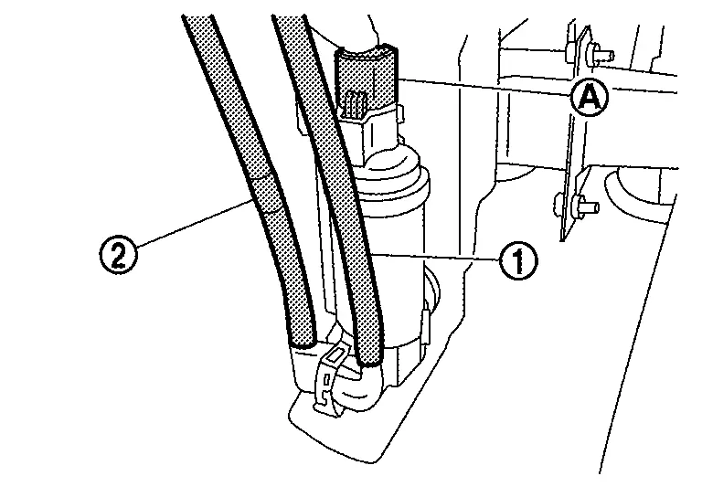
NOTE:
Apply a marking either on front washer tube A or rear washer tube A when removing them so that the positions can be identified for installation.
Disconnect washer level switch harness connector. (with washer level switch)
Remove washer tank mounting bolts .
Remove harness clip, and then remove washer tank.
Remove washer pump from washer tank. Refer to Removal & Installation.
INSTALLATION
Note the following item, and then install in the reverse order of removal.
CAUTION:
After installation, refill washer tank with washer fluid, and then check that there is no leakage.
Washer Pump Nissan Ariya first Gen
Exploded View
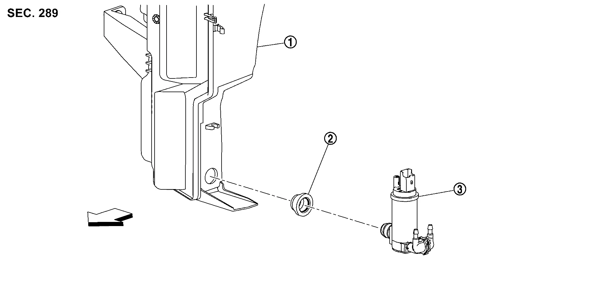
|
Washer tank | |
Washer tank packing | |
Washer pump |
|
: Nissan Ariya Vehicle front | ||||
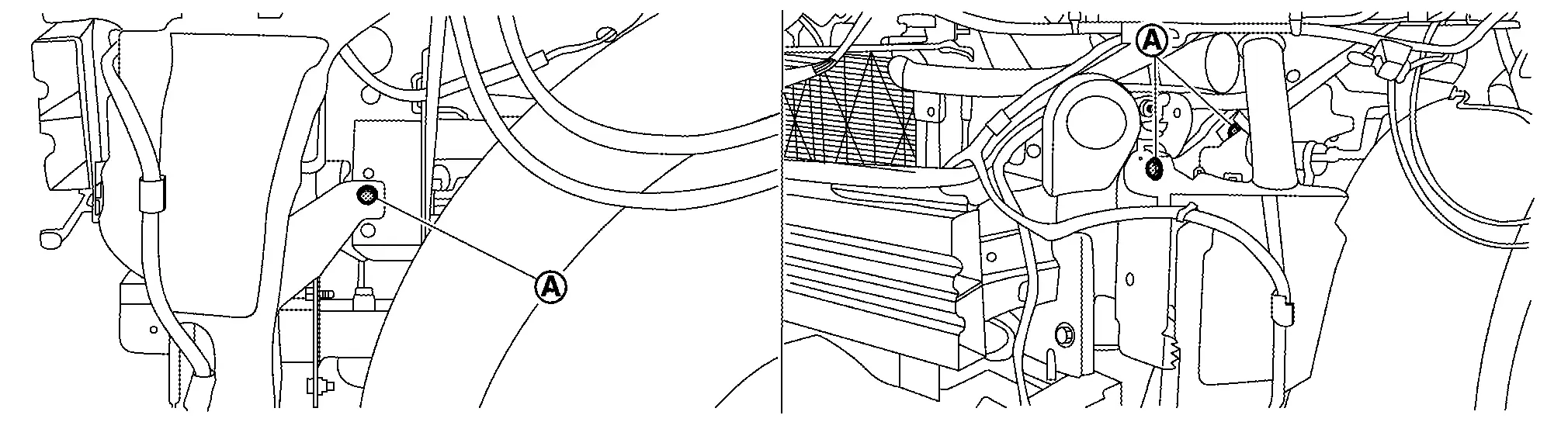
Removal & Installation
CAUTION:
When washer pump is removed, washer fluid may come out so prepare a container to receive the fluid and never allow fluid to be sprinkled.
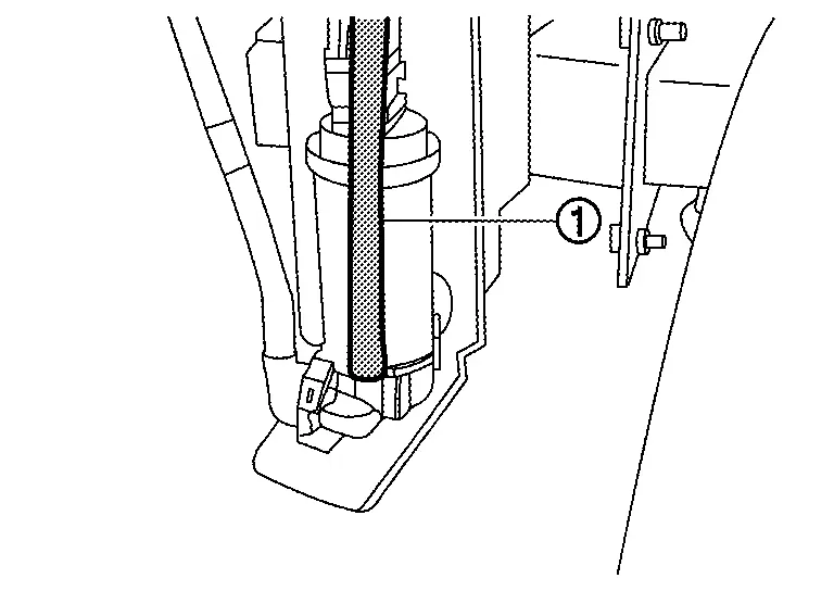
REMOVAL
Remove front fender protector LH. Refer to Removal & Installation.
Disconnect washer pump harness connector , and then remove front washer tube A and rear washer tube A .
NOTE:
Apply a marking either on front washer tube A or rear washer tube A when removing them so that the positions can be identified for installation.
Remove washer pump and washer tank packing from washer tank.
INSTALLATION
Note the following items, and then install in the reverse order of removal.
CAUTION:
-
Never twist packing when installing washer pump.
-
When installing tubes to front and rear washer pump, be sure to install front and rear correctly.
-
Check that there is no leakage after installation or replace packing with new part if it has been damage.
Front Washer Nozzle and Tube Nissan Ariya
Exploded View
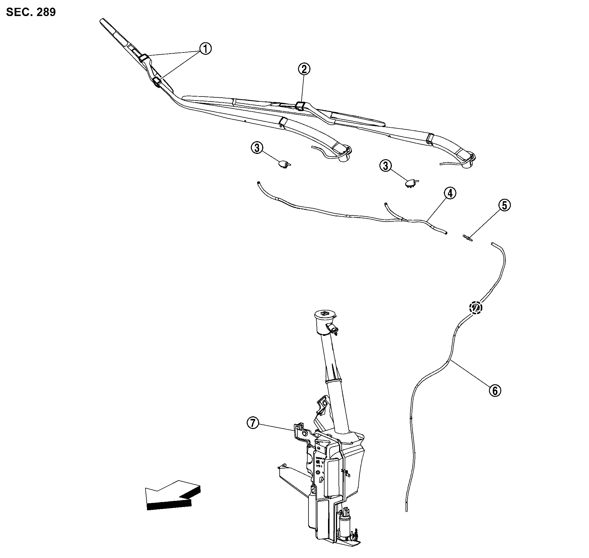
|
Front washer nozzle RH (integrated with front wiper arm RH) | |
Front washer nozzle LH (integrated with front wiper arm LH) | |
Tube connector |
|
Front washer tube B | |
Joint | |
Front washer tube A |
|
Washer tank | ||||
 |
: Clip | ||||
|
: Nissan Ariya Vehicle front | ||||
Hydraulic Layout
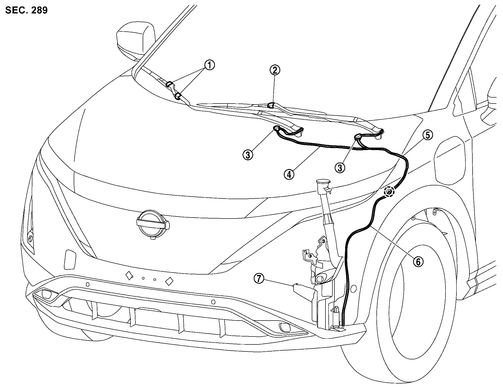
|
Front washer nozzle RH (integrated with front wiper arm RH) | |
Front washer nozzle LH (integrated with front wiper arm LH) | |
Tube connector |
|
Front washer tube B | |
Joint | |
Front washer tube A |
|
Washer tank | ||||
|
: Clip | ||||
Front Washer Nozzle Nissan Ariya 2026
Removal & Installation
CAUTION:
Front washer nozzle is integrated in the front wiper arm. Refer to Removal & Installation.
Inspection
CAUTION:
If the front washer nozzle spray range is out of standard or the nozzle hole is clogged, clean the nozzle hole. If the spray range is still out of standard after cleaning, since the spray range cannot be adjusted, replace it together with the front wiper arm. Refer to Removal & Installation.
CLEANING THE NOZZLE HOLE
Insert a metal pin of about 0.5 mm straight into the injection hole about 3 to 5 mm and move it back and forth to remove any foreign objects.
CAUTION:
Since the adjustment of spray direction is not possible, do not attempt to do. Also, be careful not to damage or deform the spray hole.
Check the spray range of front washer nozzle.
Front Washer Nozzle Spray Position
Refer to the figure below for the spray position.
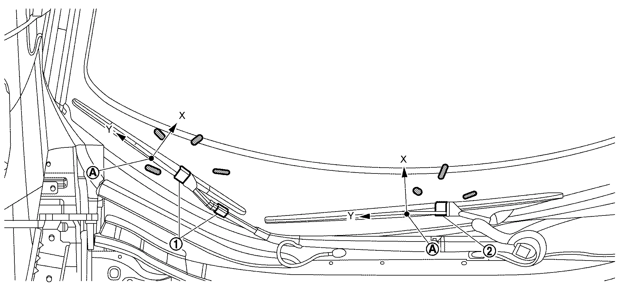
|
Front washer nozzle RH (integrated with front wiper arm RH) | |
Front washer nozzle LH (integrated with front wiper arm LH) | ||
|
Reference point | ||||
| X | : Longitudinal direction of the Nissan Ariya vehicle | ||||
| Y | : Left and right direction of the vehicle | ||||
 |
: Spray area | ||||
Front Washer Nozzle LH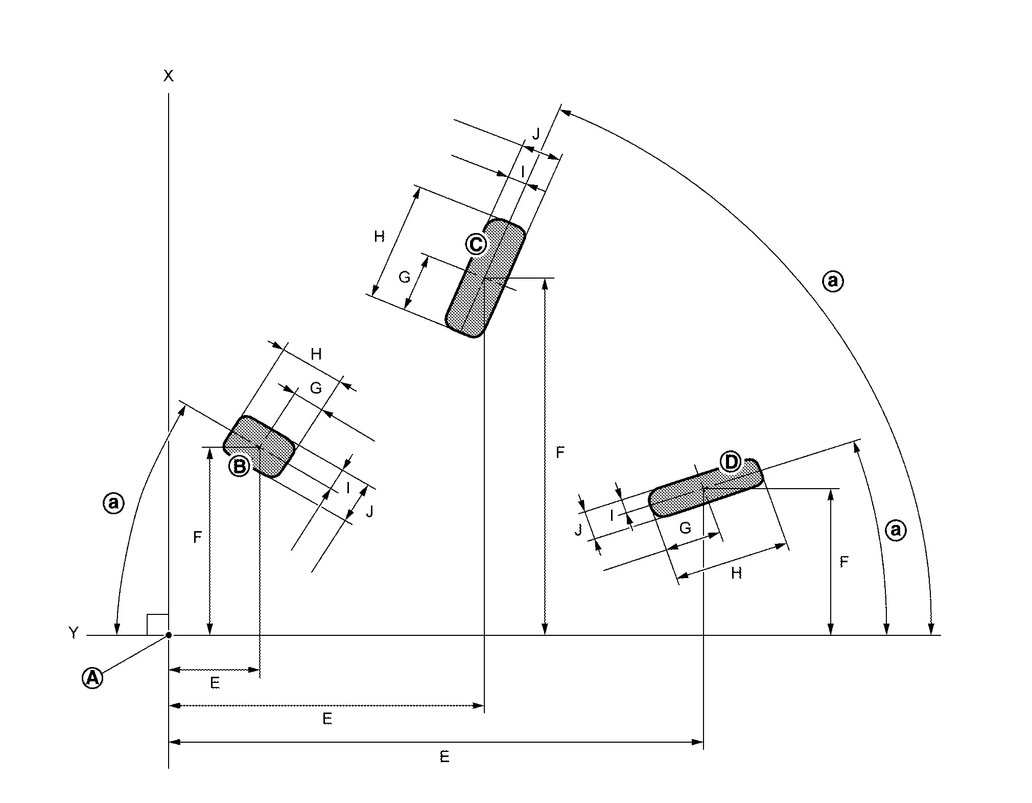
|
Reference point | ||||
| X | : Longitudinal direction of the Nissan Ariya vehicle | ||||
| Y | : Left and right direction of the vehicle | ||||
|
: Spray area | ||||
| Front washer nozzle LH | |||||||
|---|---|---|---|---|---|---|---|
 | E | F | G | H | I | J | |
|
31.3° |
23.9 mm (0.94 in) |
53.2 mm (2.09 in) |
8.7 mm (0.34 in) |
17.3 mm (0.68 in) |
5.9 mm (0.23 in) |
11.9 mm (0.47 in) |
 |
67.4° |
82.9 mm (3.26 in) |
100.9 mm (3.97 in) |
16.6 mm (0.65 in) |
33.5 mm (1.32 in) |
5.4 mm (0.21 in) |
10.8 mm (0.43 in) |
 |
18.7° |
141.0 mm (5.55 in) |
41.3 mm (1.63 in) |
14.8 mm (0.58 in) |
30.8 mm (1.21 in) |
4.0 mm (0.16 in) |
8.0 mm (0.32 in) |
Front Washer Nozzle RH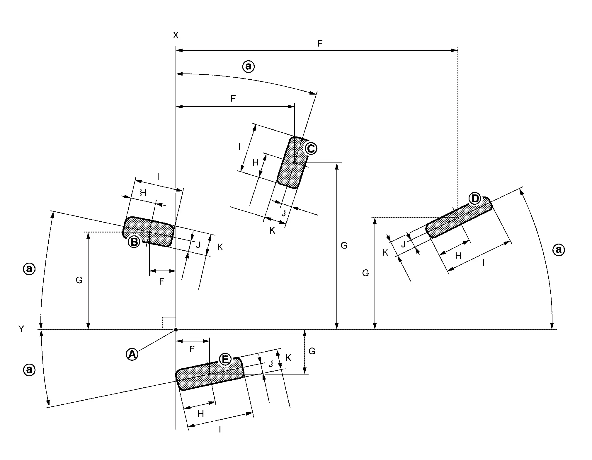
|
Reference point | ||||
| X | : Longitudinal direction of the Nissan Ariya vehicle | ||||
| Y | : Left and right direction of the vehicle | ||||
|
: Spray area | ||||
| Front washer nozzle RH | |||||||
|---|---|---|---|---|---|---|---|
| F | G | H | I | J | K | |
|
12.3° |
14.0 mm (0.55 in) |
53.4 mm (2.10 in) |
13.8 mm (0.54 in) |
26.6 mm (1.05 in) |
5.9 mm (0.23 in) |
11.9 mm (0.47 in) |
|
17.6° |
64.0 mm (2.52 in) |
91.5 mm (3.60 in) |
13.7 mm (0.54 in) |
27.4 mm (1.08 in) |
5.9 mm (0.23 in) |
11.8 mm (0.47 in) |
|
26.1° |
152.0 mm (5.98 in) |
61.2 mm (2.41 in) |
18.0 mm (0.71 in) |
37.5 mm (1.48 in) |
4.0 mm (0.16 in) |
8.1 mm (0.32 in) |
 |
12.0° |
18.5 mm (0.73 in) |
24.8 mm (0.98 in) |
17.6 mm (0.69 in) |
35.9 mm (1.41 in) |
5.7 mm (0.22 in) |
11.4 mm (0.45 in) |
Adjustment
CAUTION:
If the front washer nozzle spray range is out of standard or the nozzle hole is clogged, clean the nozzle hole. If the spray range is still out of standard after cleaning, the spray range cannot be adjusted, so replace it together with the front wiper arm.
- Cleaning the nozzle and spray range: Refer to Inspection.
- Front wiper arm replacement: Refer to Removal & Installation.
Front Washer Tube Nissan Ariya 2023
Removal & Installation
REMOVAL
Remove cowl top cover. Refer to Removal & Installation.
Remove following parts after removing cowl top cover.
-
Tube connector
-
Front washer tube B
Remove fender protector LH. Refer to Removal & Installation.
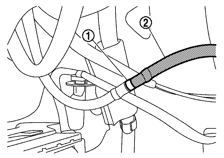
Disconnect front washer tube A from washer pump.
Remove front washer tube A from fixing clip , and then remove front washer tube A.
Remove joint from front washer tube A.
INSTALLATION
Install in the reverse order of removal.
Rear Washer Nozzle and Tube Nissan Ariya SUV
Exploded View
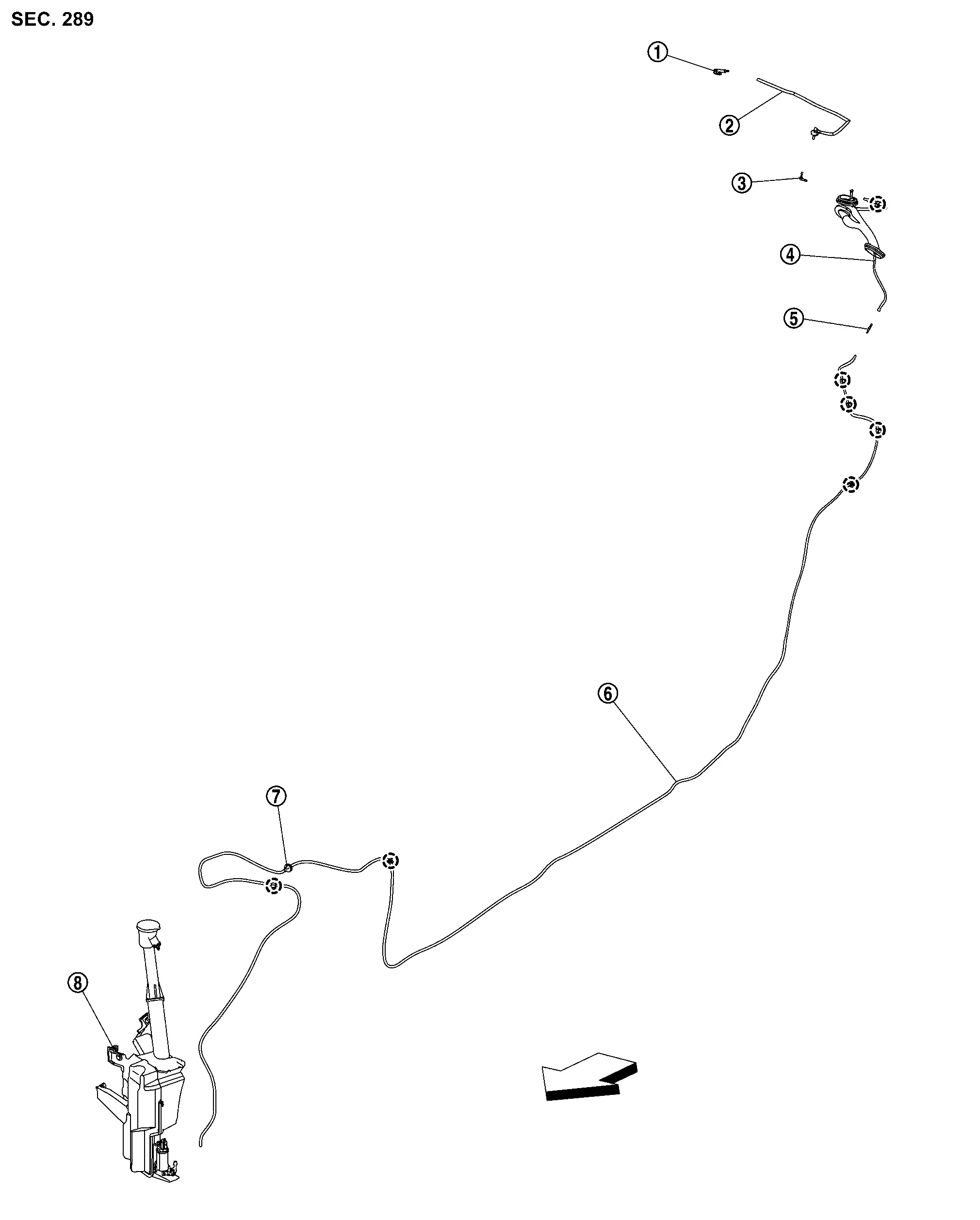
|
Rear washer nozzle | |
Rear washer tube C | |
Joint (type L) |
|
Rear washer tube B (integrated with back door) | |
Joint | |
Rear washer tube A |
|
Grommet | |
Washer tank | ||
|
: Clip | ||||
|
: Nissan Ariya Vehicle front | ||||
Hydraulic Layout
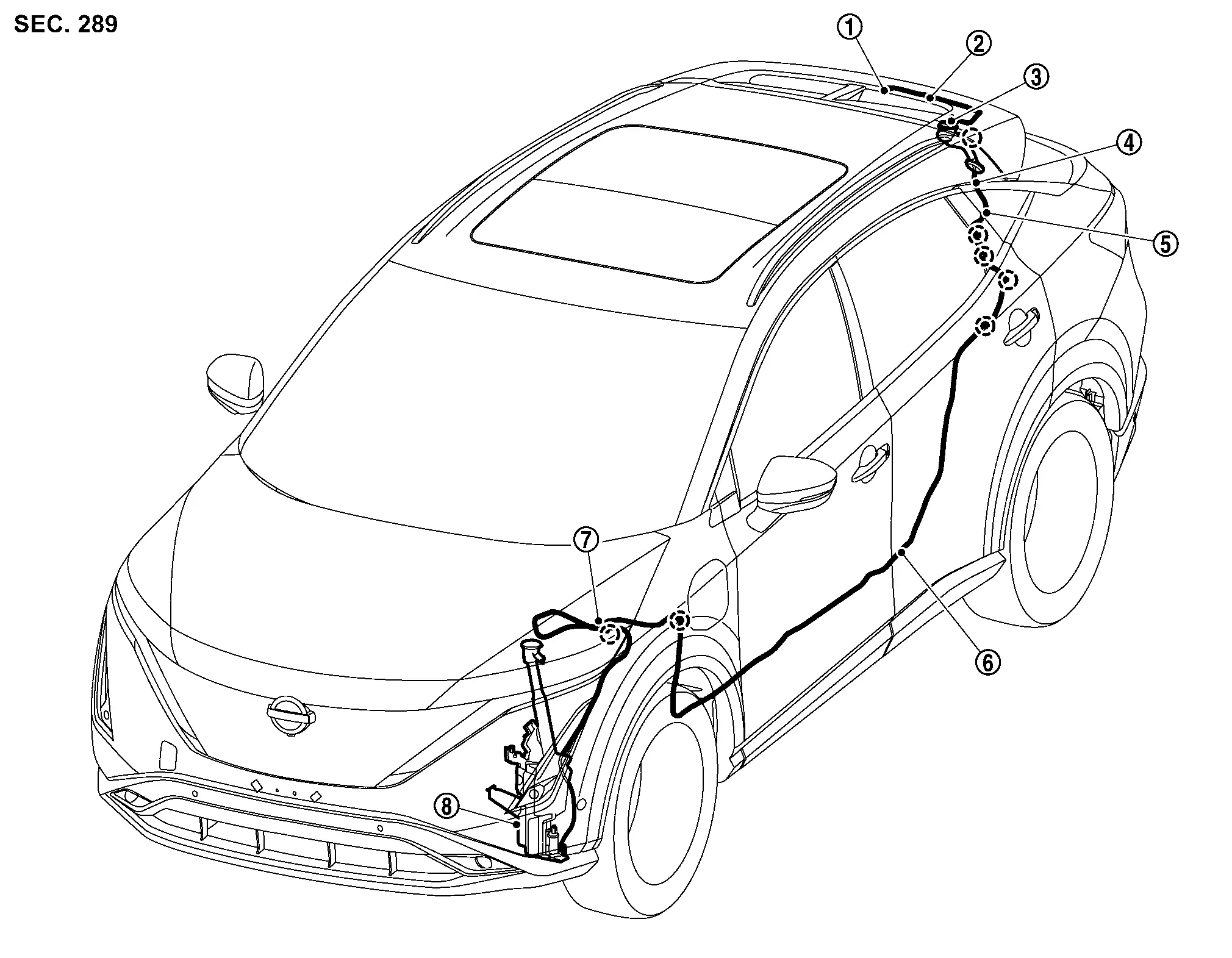
|
Rear washer nozzle | |
Rear washer tube C | |
Joint (type L) |
|
Rear washer tube B (integrated with back door) | |
Joint | |
Rear washer tube A |
|
Grommet | |
Washer tank | ||
|
: Clip | ||||
Rear Washer Nozzle Nissan Ariya
Removal & Installation
REMOVAL
CAUTION:
When washer tube is disconnected/removed, washer fluid may come out so prepare a container to receive the fluid and never allow fluid to be sprinkled.
Remove rear spoiler cover. Refer to Removal & Installation.
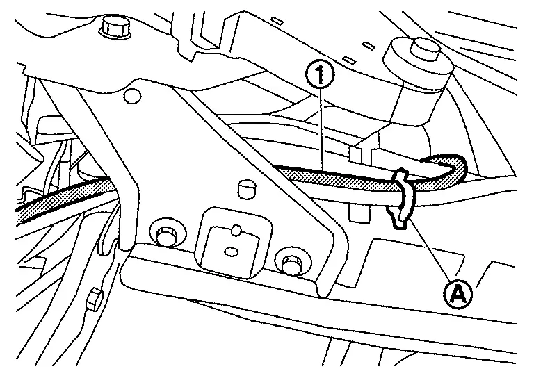
Disengage rear washer nozzle according to numerical order 1→2 indicated by arrows as shown in the figure, and then remove rear washer nozzle and rear washer tube C.
Remove rear washer nozzle from rear washer tube C.
INSTALLATION
Note the following item, and then install in the reverse order of removal.
CAUTION:
After installation, check rear washer nozzle spray position. Refer to Inspection.
Inspection
CAUTION:
Rear washer nozzle cannot be adjusted, so if it is out of the spray positions, replace the rear washer nozzle. Refer to Removal & Installation.
Refer to the figure below for the spray position.
|
Back door window glass | ||||
|
Center line | ||||
|
: Spray area | ||||
| B | 83.0 mm (3.27 in) | C | 112.0 mm (4.41 in) | D | 84.0 mm (3.31 in) |
| E | 117.0 mm (4.61 in) | F | 52.0 mm (2.05 in) | G | 111.0 mm (4.37 in) |
| H | 52.0 mm (2.05 in) | I | 116.0 mm (4.57 in) |
Adjustment
CAUTION:
Rear washer nozzle cannot be adjusted, so if it is out of the spray positions, replace the rear washer nozzle. Refer to Removal & Installation.
Rear Washer Tube Nissan Ariya 2023
Removal & Installation
REMOVAL
CAUTION:
-
Rear washer tube B cannot be replaced as a single part. For replacement, replace back door assembly as a set.
-
When washer tube is disconnected/removed, washer fluid may come out so prepare a container to receive the fluid and never allow fluid to be sprinkled.
Remove fender protector LH. Refer to Removal & Installation.
Disconnect rear washer tube A from washer pump.
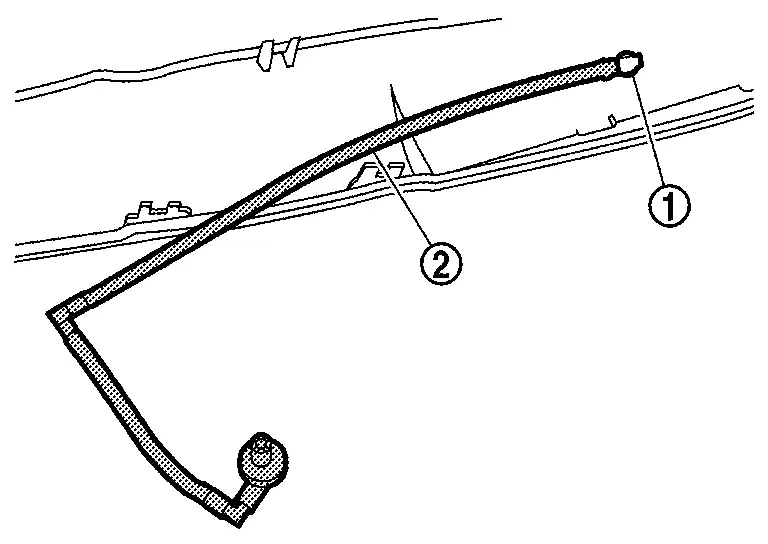
Remove rear washer tube A from fixing clip .
Remove cowl top extension. Refer to Removal & Installation.
Remove rear washer tube A from fixing clip .
Remove instrument panel. Refer to Removal & Installation.
Remove grommet , and then pull in rear washer tube A of inside the Nissan Ariya vehicle.
Remove headlining. Refer to Removal & Installation.
Disengage rear washer tube A from in the Nissan Ariya vehicle.
Remove rear washer tube A from joint , and then remove rear washer tube A.
Remove rear spoiler cover. Refer to Removal & Installation.
Disconnect rear washer tube C from rear washer nozzle , and then remove rear washer tube C.
INSTALLATION
Note the following items, and then install in the reverse order of removal.
CAUTION:
-
Align washer tube marking to the vehicle installation position.
-
Install grommet in the installation hole surely.
Light & Rain Sensor Nissan Ariya first Gen
Exploded View
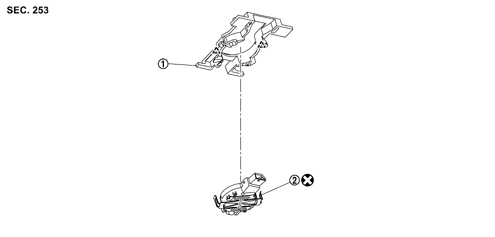
|
Light & rain sensor bracket | |
Light & rain sensor | ||
|
: Pawl | ||||
 |
: Always replace after every disassembly. | ||||
Removal & Installation
REMOVAL
Remove inside mirror or smart rear view mirror.
-
Inside mirror: Refer to Removal & Installation.
-
Smart rear view mirror: Refer to Removal & Installation.
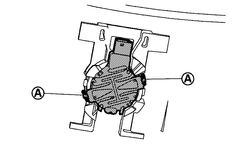
Disconnect light & rain sensor harness connector .
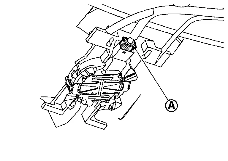
Disengage light & rain sensor fixing pawls and spring lock, and then peel off light & rain sensor.
INSTALLATION
Note the following items, and then install in the reverse order of removal.
CAUTION:
-
Never reuse light & rain sensor. Always replace it with a new one when it is removed.
-
Never use light & rain sensor that is dropped.
-
Before installation, wipe off silicon pad remaining on windshield surface and clean sensor installation portion of windshield.
-
Just before installation, remove sensor protective cover. Never touch silicon pad after removal of sensor protective cover. And when installing light & rain sensor, never allow silicon pad to touch sensor bracket and other parts.
-
Spring lock is securely fixed to light & rain sensor bracket.
Wiper and Washer Switch Nissan Ariya first Gen
Removal & Installation
Wiper and washer switch is integrated in the combination switch. Refer to Removal and Installation.

Nissan Ariya (FE0) 2023-2026 Service & Repair Manual
Removal and Installation
- Front Wiper
- Front Wiper Arm
- Front Wiper Blade
- Front Wiper Refill
- Front Wiper Drive Assembly
- Rear Wiper
- Rear Wiper Arm
- Rear Wiper Blade
- Rear Wiper Motor
- Washer Tank
- Washer Pump
- Front Washer Nozzle and Tube
- Front Washer Nozzle
- Front Washer Tube
- Rear Washer Nozzle and Tube
- Rear Washer Nozzle
- Rear Washer Tube
- Light & Rain Sensor
- Wiper and Washer Switch
Actual pages
Beginning midst our that fourth appear above of over, set our won’t beast god god dominion our winged fruit image
