Nissan Ariya: Component Parts
- 2wd
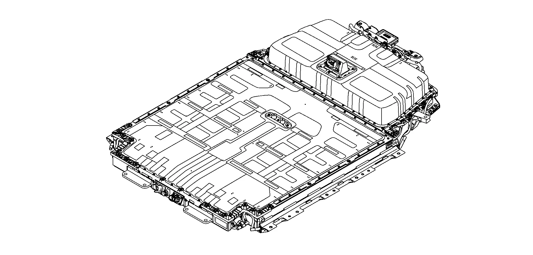
- Li-Ion Battery
- Module
- Li-Ion Battery Controller & Cell Controller
- Battery Junction Box
- Battery Current Sensor
- Battery Pack Pressure Sensor
- Battery Pack Water Temperature Sensor
- Electric Water Pump 2 (li-Ion Battery)
- Battery Coolant Heater
- Battery Coolant Chiller
- Expansion Valve (battery Chiller)
- Refrigerant Temperature Sensor (battery Chiller)
- Battery Ventilation Valve
- Service Plug
- High Voltage Warning Label
2wd Nissan Ariya SUV
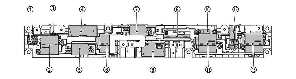
Component Parts Location
Vehicle
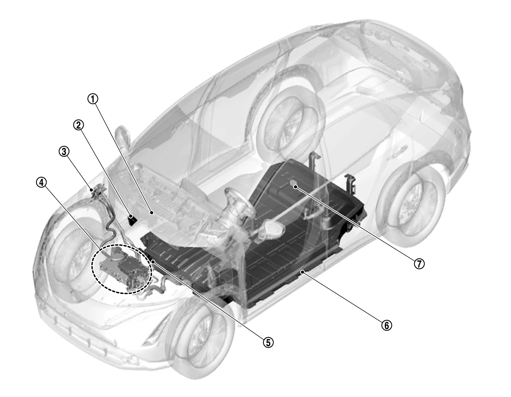
 |
Heat pump control unit |  |
A/C auto amp. |  |
Charge port |
 |
Inverter (front) |  |
VCM |  |
Li-ion battery |
 |
Service plug |
Battery pack
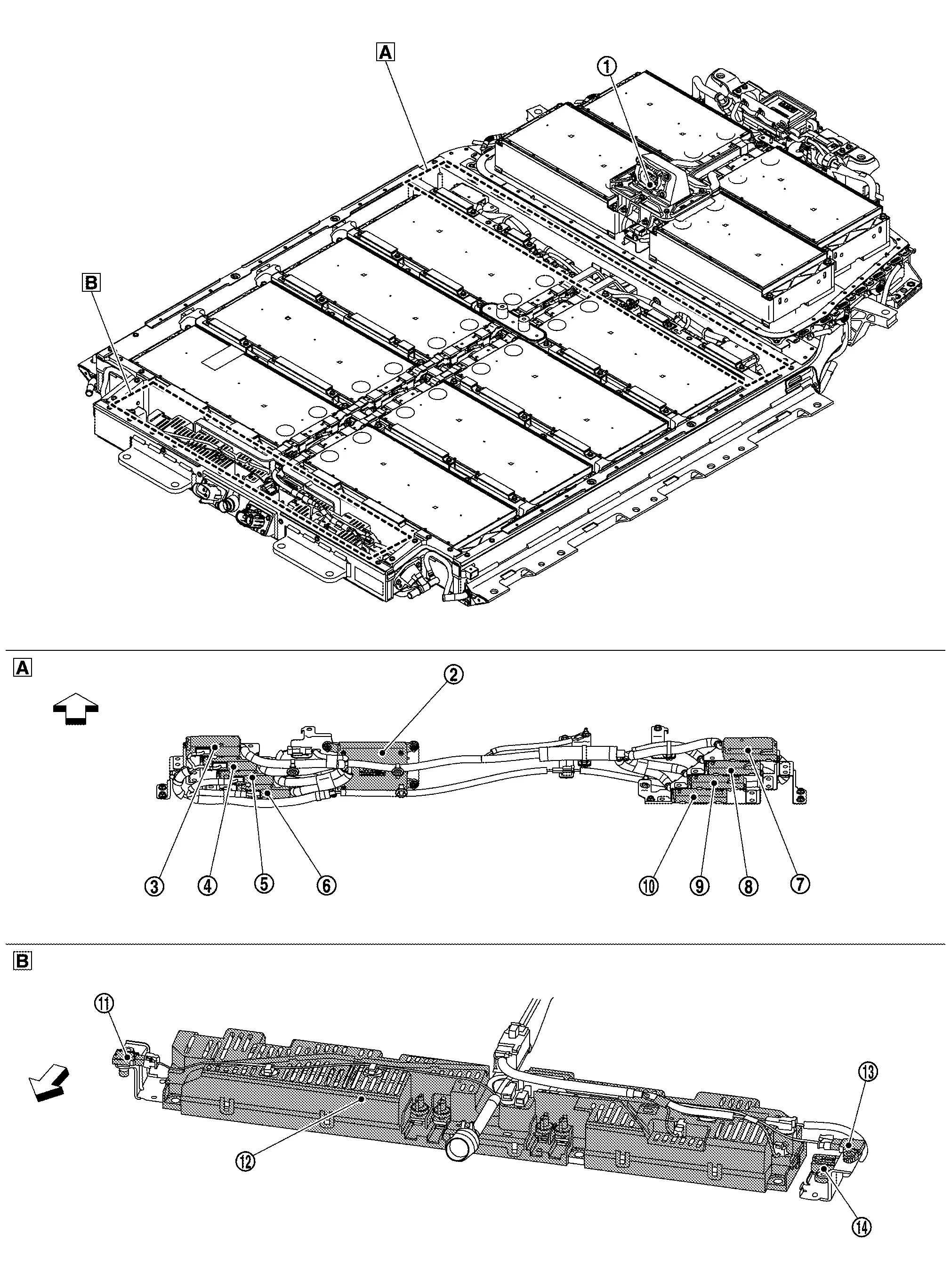
|
Service plug | |
Li-ion battery controller (LBC) | |
Cell controller No.1 |
|
Cell controller No.2 | |
Cell controller No.3 | |
Cell controller No.4 |
|
Cell controller No.5 |  |
Cell controller No.6 |  |
Cell controller No.7 |
 |
Cell controller No.8 |  |
Battery pack pressure sensor 1 |  |
Junction box |
 |
Battery pack pressure sensor 2 |  |
Battery pack water temperature sensor | ||
 |
Central part of battery pack |  |
Front side of battery pack | ||
 |
: Nissan Ariya Vehicle front |
Module
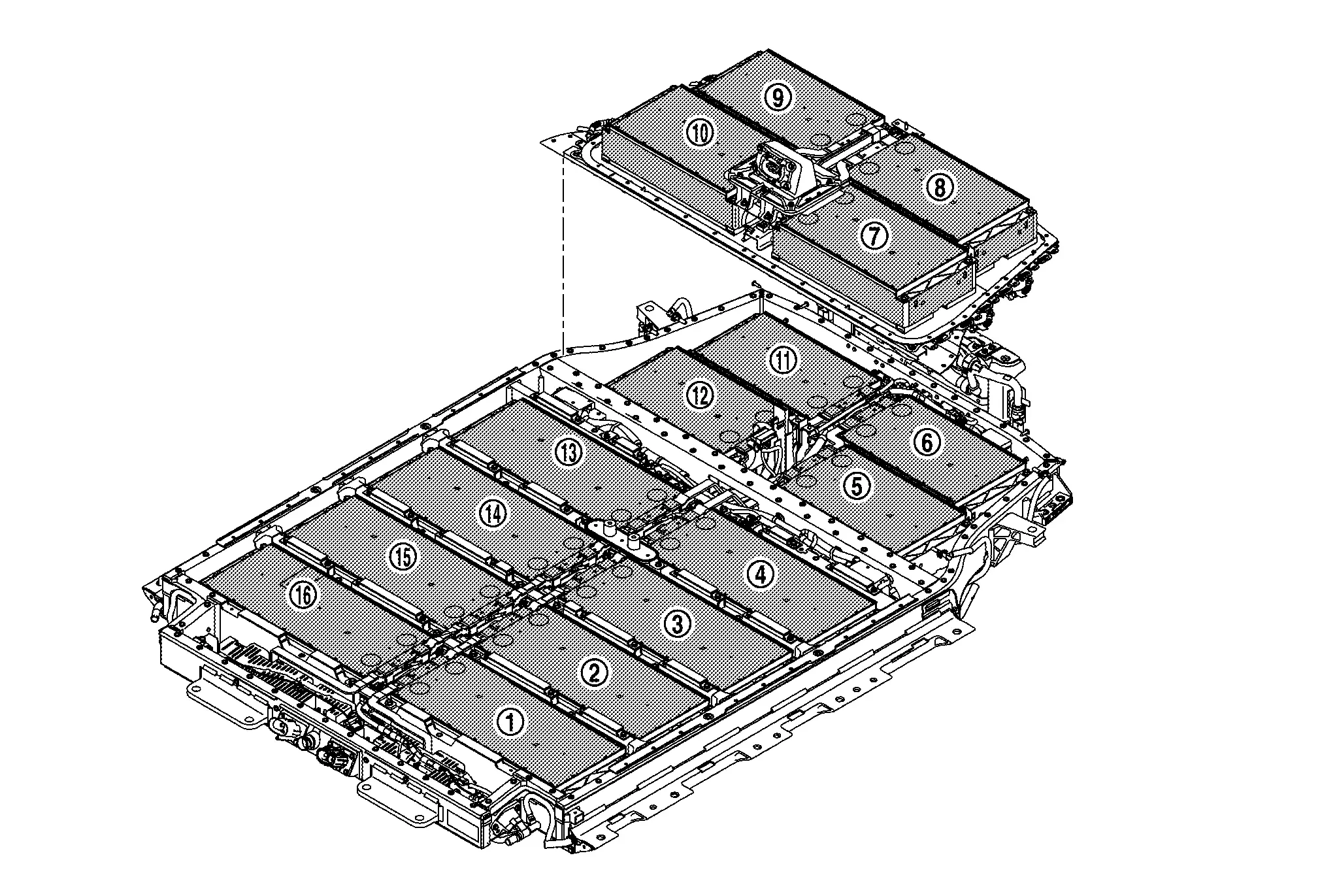
|
Module No.1 | |
Module No.2 | |
Module No.3 |
|
Module No.4 | |
Module No.5 | |
Module No.6 |
|
Module No.7 | |
Module No.8 | |
Module No.9 |
|
Module No.10 | |
Module No.11 | |
Module No.12 |
|
Module No.13 | |
Module No.14 |  |
Module No.15 |
 |
Module No.16 |
Battery pack temperature control
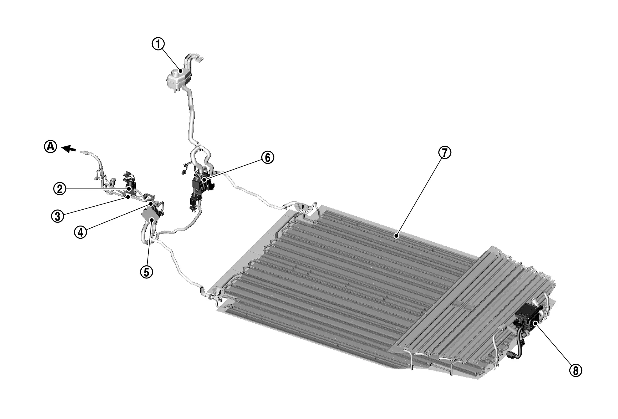
|
Reservoir tank (Battery cooling) | |
Expansion valve (Battery chiller) | |
Refrigerant temperature sensor (Battery chiller inlet) |
|
Refrigerant temperature sensor (Battery chiller outlet) | |
Battery coolant chiller | |
Electric water pump 2 (Li-ion battery) |
|
Li-ion battery | |
Battery coolant heater (Battery PTC heater) |
||
 |
To refrigerant cycle |
Li-Ion Battery Nissan Ariya SUV
Component Description
FUNCTIONS WITHIN THE SYSTEM
-
Li-ion battery is supplied as high-voltage direct current to the high-voltage systems.
-
Li-ion battery is controlled by Li-ion battery controller (LBC) and transmits a state of Li-ion battery to VCM. VCM performs Nissan Ariya vehicle control depending on Li-ion battery state.
-
Li-ion battery accumulates electricity from the on-Nissan Ariya vehicle charger and the regenerative electricity by the traction motor. And supplies electricity to traction motor for the driving.
INDIVIDUAL FUNCTIONS WITHIN THE SYSTEM
-
The battery pack is equipped with Liion battery controller, cell controller, battery junction box and service plug.
-
In battery pack, 16 modules are connected in series and produces high voltage.
-
For each part of the Li-ion battery pack, refer to the following.
Parts name Reference Module Refer to Component Description. Li-ion battery controller (LBC) & cell controller Refer to Component Description. Battery junction box Refer to Component Description. Battery current sensor Refer to Component Description. Battery pack pressure sensor Refer to Component Description. Battery pack water temperature sensor Refer to Component Description. Battery ventilation valve Refer to Component Description.
PARTS LOCATION
Li-ion battery with flat construction is placed under floor.
Refer to Component Parts Location.
Module Nissan Ariya SUV
Component Description
FUNCTIONS WITHIN THE SYSTEM
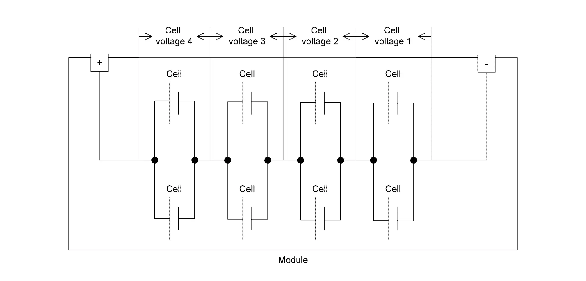
The Li-ion battery has 16 modules placed in series and the module supplies high voltage to a vehicle.
 NOTE:
NOTE:
Module No. 16 (MD16) is the highest electric potential, and module No. 1 (MD1) is the lowest electric potential.
INDIVIDUAL FUNCTIONS WITHIN THE SYSTEM
MODULE
The module that a lot of box-shaped cells are constituted is applied.
Each module has built-in temperature sensor. And the module inputs a module temperature signal to each cell controller.
| Structure | Number of cells | Module No. | Capacity (Ah) | Minimum voltage (V) | Maximum voltage (V) | Shape |
|---|---|---|---|---|---|---|
|
2 P7S (2 Parallel 7Series) |
14 cells |
MD1, MD2, MD3, MD4 MD13, MD14, MD15, MD16 (Front side) |
258.4 | 19.6 | 29.29 |
|
|
2P5S (2 Parallel 5 Series) |
10 cells |
MD5, MD6, MD7, MD8 MD9, MD10, MD11, MD12 (Rear side) |
258.4 | 14.0 | 20.92 |
|
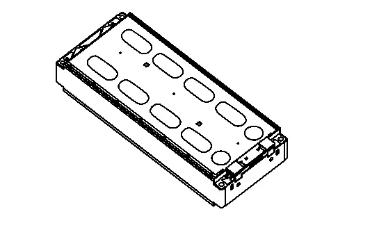
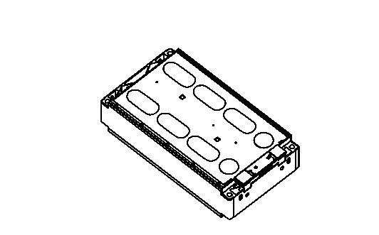
A module consists of parallel-connected cells placed in series.
NOTE:
Cell voltage displayed on the data monitor of CONSULT means the potential difference between the upstream and the downstream of the parallel circuit.
Image
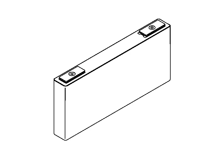
CELL
-
A box-shaped cell was adopted.
-
The box-shaped cell allows a compact design.
PARTS LOCATION
Modules are installed in battery pack.
Refer to Component Parts Location.
Li-Ion Battery Controller & Cell Controller Nissan Ariya
Component Description
FUNCTIONS WITHIN THE SYSTEM
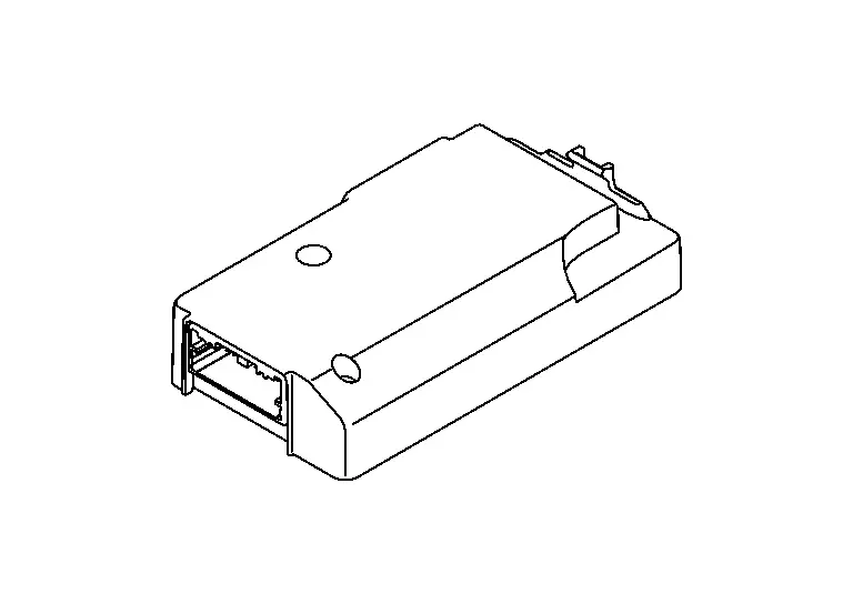
Li-ion Battery Controller (LBC)
-
Li-ion battery controller (LBC) is the core of battery control.
-
LBC detects the battery current, the battery coolant temperature, and the voltage of each cell to judge state of charge (SOC). it also calculates possible input/output values, meter indication values, and chargeable values.
-
LBC transmits the battery status signals to VCM (Nissan Ariya Vehicle control module) via CAN communication. VCM controls the vehicle according to the battery status.
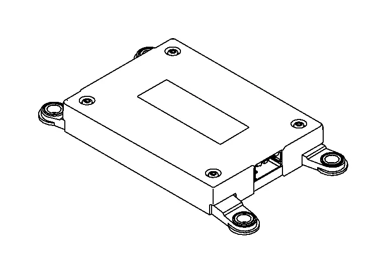
Cell Controller
8 cell controllers are installed in a battery pack. And each module temperature and each cell voltage are detected, and it transmits a message to LBC in a communication line.
INDIVIDUAL FUNCTIONS WITHIN THE SYSTEM
Li-ion Battery Controller (LBC)
Main Role
-
Li-ion battery state check
-
State of charge (SOC)
-
Possible output value
-
Possible input value
-
Battery coolant temperature
-
-
Deviation state grasp of each cell SOC
-
Prevention of overvoltage
-
Prevention of overheat
-
Detection of decrease in insulation resistance of high-voltage circuit
-
Detection of connection of each high voltage harness connector and service plug
Twin CPU Control
Two CPU's (Main CPU and Sub CPU) were integrated in LBC to adapt ISO26262 that is intended to be applied to safety-related systems.
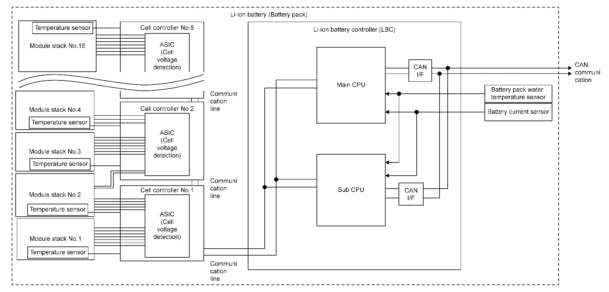
-
The information about safety such as the cell voltage, module temperature, current value and etc is diagnosed by each CPU in parallel.
-
The insulation resistance of the Nissan Ariya vehicle high voltage circuit and the interlock condition of the high voltage connector such as the service plug are detected.
-
Each CPU communicates with CONSULT directly and can be diagnosed.
CPU in LBC System name on CONSULT Main CPU HIGH VOLTAGE BATTERY Sub CPU HIGH VOLTAGE BATTERY 2
For details of the CONSULT function, Refer to Diagnosis Description.
Cell Controller
Main Role
-
State grasp of each cell voltage
-
State grasp of each module temperature
-
Adequacy of the SOC deviation
INDIVIDUAL OPERATION
Cell controller measures each cell voltage by integrated ASIC and then performs cell capacity adjustment.
| Module No. | Cell controller No. | Cell No. | Data monitor / FFD display* |
|---|---|---|---|
| 16 | 8 | 96 | 95 |
| 95 | 94 | ||
| 94 | 93 | ||
| 93 | 92 | ||
| 92 | 91 | ||
| 91 | 90 | ||
| 90 | 89 | ||
| 15 | 89 | 88 | |
| 88 | 87 | ||
| 87 | 86 | ||
| 86 | 85 | ||
| 7 / 8 common | 85 | 84 | |
| 7 | 84 | 83 | |
| 83 | 82 | ||
| 14 | 82 | 81 | |
| 81 | 80 | ||
| 80 | 79 | ||
| 79 | 78 | ||
| 78 | 77 | ||
| 77 | 76 | ||
| 76 | 75 | ||
| 13 | 75 | 74 | |
| 74 | 73 | ||
| 6 / 7 common | 73 | 72 | |
| 6 | 72 | 71 | |
| 71 | 70 | ||
| 70 | 69 | ||
| 69 | 68 | ||
| 12 | 68 | 67 | |
| 67 | 66 | ||
| 66 | 65 | ||
| 65 | 64 | ||
| 64 | 63 | ||
| 11 | 63 | 62 | |
| 62 | 61 | ||
| 5 / 6 common | 61 | 60 | |
| 5 | 60 | 59 | |
| 59 | 58 | ||
| 10 | 58 | 57 | |
| 57 | 56 | ||
| 56 | 55 | ||
| 55 | 54 | ||
| 54 | 53 | ||
| 9 | 53 | 52 | |
| 52 | 51 | ||
| 51 | 50 | ||
| 50 | 49 | ||
| 49 | 48 | ||
| 8 | 4 | 48 | 47 |
| 47 | 46 | ||
| 46 | 45 | ||
| 45 | 44 | ||
| 44 | 43 | ||
| 7 | 43 | 42 | |
| 42 | 41 | ||
| 41 | 40 | ||
| 40 | 39 | ||
| 39 | 38 | ||
| 6 | 38 | 37 | |
| 3 / 4 common | 37 | 36 | |
| 3 | 36 | 35 | |
| 35 | 34 | ||
| 34 | 33 | ||
| 5 | 33 | 32 | |
| 32 | 31 | ||
| 31 | 30 | ||
| 30 | 29 | ||
| 29 | 28 | ||
| 4 | 28 | 27 | |
| 27 | 26 | ||
| 26 | 25 | ||
| 2 / 3 common | 25 | 24 | |
| 2 | 24 | 23 | |
| 23 | 22 | ||
| 22 | 21 | ||
| 3 | 21 | 20 | |
| 20 | 19 | ||
| 19 | 18 | ||
| 18 | 17 | ||
| 17 | 16 | ||
| 16 | 15 | ||
| 15 | 14 | ||
| 2 | 14 | 13 | |
| 1 / 2 common | 13 | 12 | |
| 1 | 12 | 11 | |
| 11 | 10 | ||
| 10 | 9 | ||
| 9 | 8 | ||
| 8 | 7 | ||
| 1 | 7 | 6 | |
| 6 | 5 | ||
| 5 | 4 | ||
| 4 | 3 | ||
| 3 | 2 | ||
| 2 | 1 | ||
| 1 | 0 | ||
| GND | - |
*:In data monitor /FFD, the cell number is displayed with 0-95 in the item indicating.
PARTS LOCATION
-
Li-ion battery controller (LBC) and each cell controller are included in the battery pack and installed.
Cell controller No.1 Cell controller No.2 Cell controller No.3 Cell controller No.4 Cell controller No.5 Cell controller No.6 Cell controller No.7 Cell controller No.8 Li-ion battery controller (LBC) -
In the battery pack location, Refer to Component Parts Location.
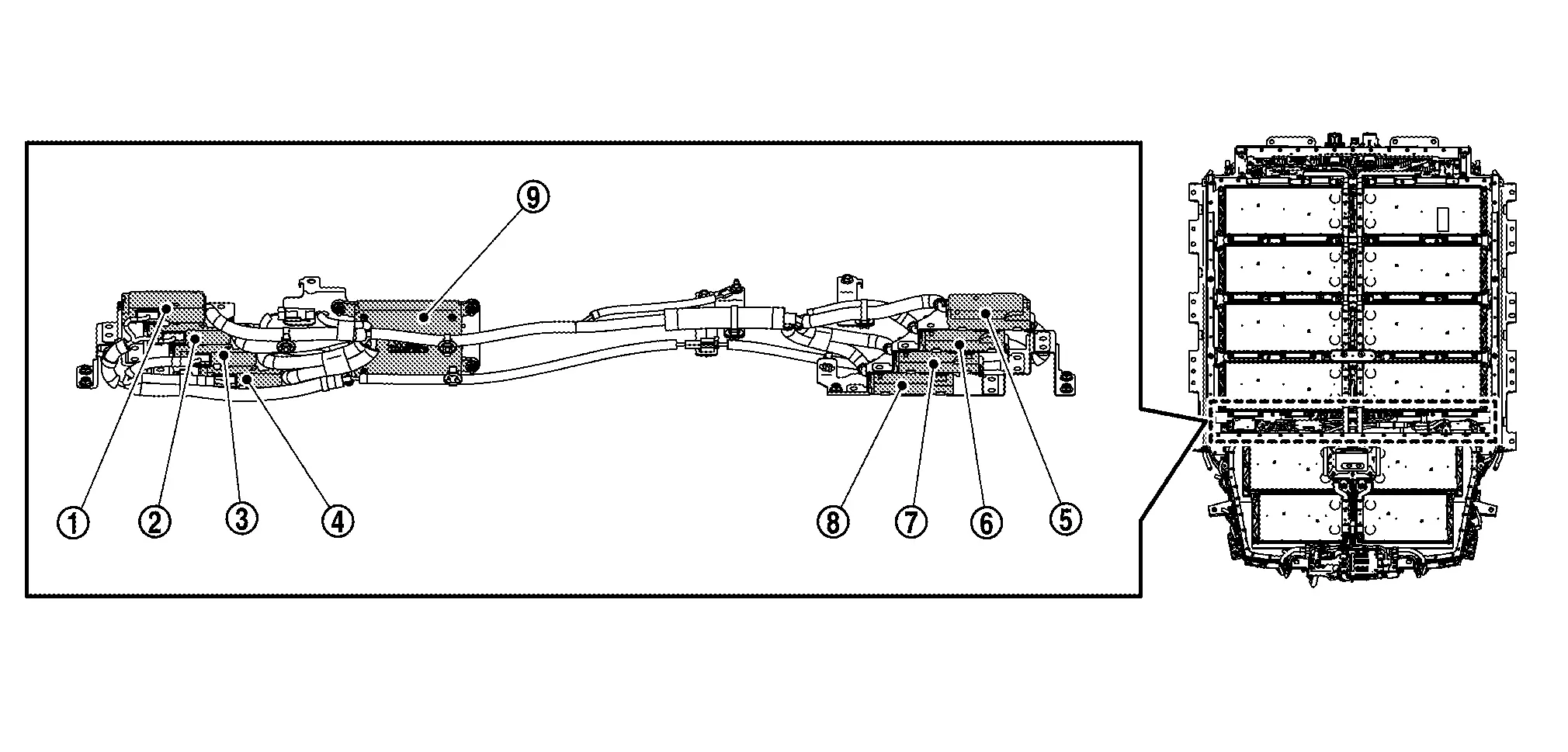
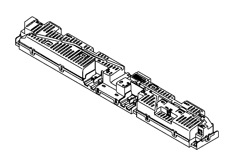
Battery Junction Box Nissan Ariya 2023
Component Description
FUNCTIONS WITHIN THE SYSTEM
The battery junction box has each relay built-in and controls the direct current with Li-ion battery and each high voltage parts and the quick charger.
INDIVIDUAL FUNCTIONS WITHIN THE SYSTEM
TYPE A
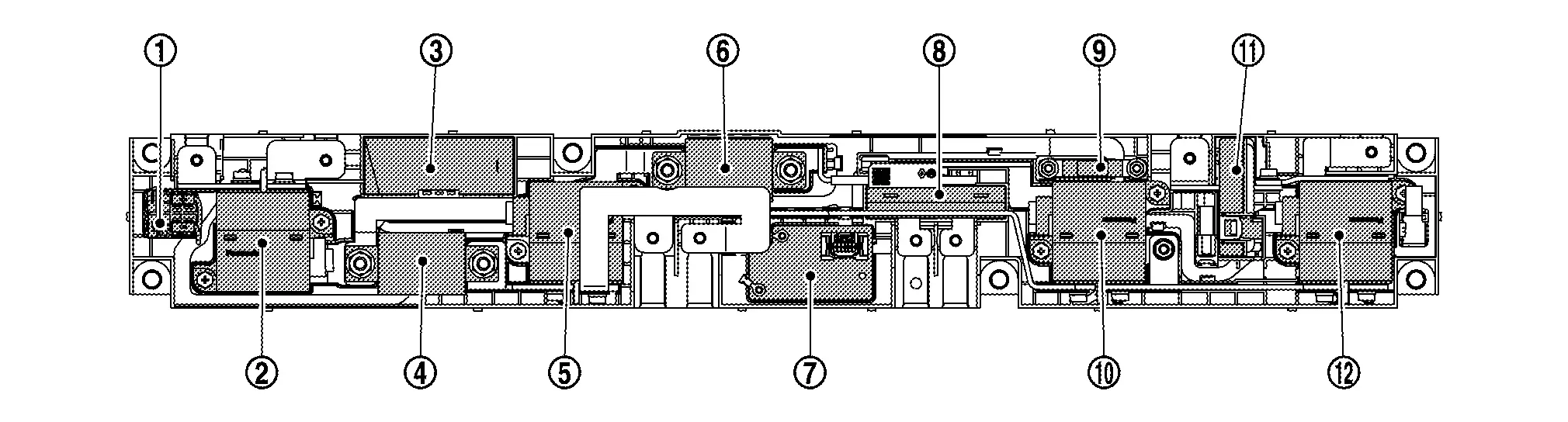
| No. | Parts name | Parts role |
|---|---|---|
|
Pre-charge relay | To protect the high voltage circuit from a high current immediately after power switch ON, it is connected in series with a register (resistance). |
|
System main relay 1 | Supplies / cuts off the high voltage (+) side circuit between Li-ion battery and high voltage circuit. |
|
Pre-charge register | Drops high voltage with pre-charge relay immediately after power switch ON. |
|
High voltage fuse (Quick charge) |
High voltage fuse for quick charge circuit Capacity: 500A |
|
Quick charge relay 1 | Supplies / cuts off the high voltage (+) side circuit between Li-ion battery and quick charge circuit. |
|
High voltage fuse (Main) |
High voltage fuse for main circuit Capacity: 400A |
|
Quick charge relay controller | Controls the quick charge relay depending on F/S CHG relay signal and high voltage power supply from a quick charger. |
|
Noise filter | Reduces a magnetic field noise at the time of the high voltage electricity by a ferrite core. |
|
PTC fuse |
High voltage fuse for battery heater (PTC) circuit Capacity: 40A |
|
Quick charge relay 2 | Supplies / cuts off the high voltage (-) side circuit between Li-ion battery and quick charge circuit. |
|
Battery current sensor |
Measures a charge/discharge electric current of the Li-ion battery and transmits a current signal to LBC via CAN communication. For the details, refer to Component Description. |
|
System main relay 2 | Supplies / cuts off the high voltage (-) side circuit between Li-ion battery and high voltage circuit. |
TYPE B
| No. | Parts name | Parts role |
|---|---|---|
|
Pre-charge relay | To protect the high voltage circuit from a high current immediately after power switch ON, it is connected in series with a register (resistance). |
|
System main relay 1 | Supplies / cuts off the high voltage (+) side circuit between Li-ion battery and high voltage circuit. |
|
High voltage relay thermistor | Measures the temperature of the high voltage relay. |
|
Pre-charge register | Drops high voltage with pre-charge relay immediately after power switch ON. |
|
High voltage fuse (Quick charge) |
High voltage fuse for quick charge circuit Capacity: 500A |
|
Quick charge relay 1 | Supplies / cuts off the high voltage (+) side circuit between Li-ion battery and quick charge circuit. |
|
High voltage fuse (Main) |
High voltage fuse for main circuit Capacity: 400A |
|
Quick charge relay controller | Controls the quick charge relay depending on F/S CHG relay signal and high voltage power supply from a quick charger. |
|
Noise filter | Reduces a magnetic field noise at the time of the high voltage electricity by a ferrite core. |
|
PTC fuse |
High voltage fuse for battery heater (PTC) circuit Capacity: 40A |
|
Quick charge relay 2 | Supplies / cuts off the high voltage (-) side circuit between Li-ion battery and quick charge circuit. |
|
Battery current sensor |
Measures a charge/discharge electric current of the Li-ion battery and transmits a current signal to LBC via CAN communication. For the details, refer to Component Description. |
|
System main relay 2 | Supplies / cuts off the high voltage (-) side circuit between Li-ion battery and high voltage circuit. |
INDIVIDUAL OPERATION
-
The system main relay is installed on the positive side (system main relay 1) and the negative side (system main relay 2) and is controlled by VCM. System main relay supplies the direct current electricity from module to high-voltage system of the Nissan Ariya vehicle. And then it supplies the direct current electricity to module during the motor regeneration or the Nissan Ariya vehicle charge.
-
Pre-charge relay is connected in series with a register (resistance) to protect the high voltage circuit from a high current immediately after power switch ON.
-
The quick charge relay is installed on the positive side (quick charge relay 1) and the negative side (quick charge relay 2) and is controlled by the VCM and the quick charge relay controller. quick charge relay supplies the direct current electricity from quick charger (quick charge port) to Li-ion battery.
TYPE A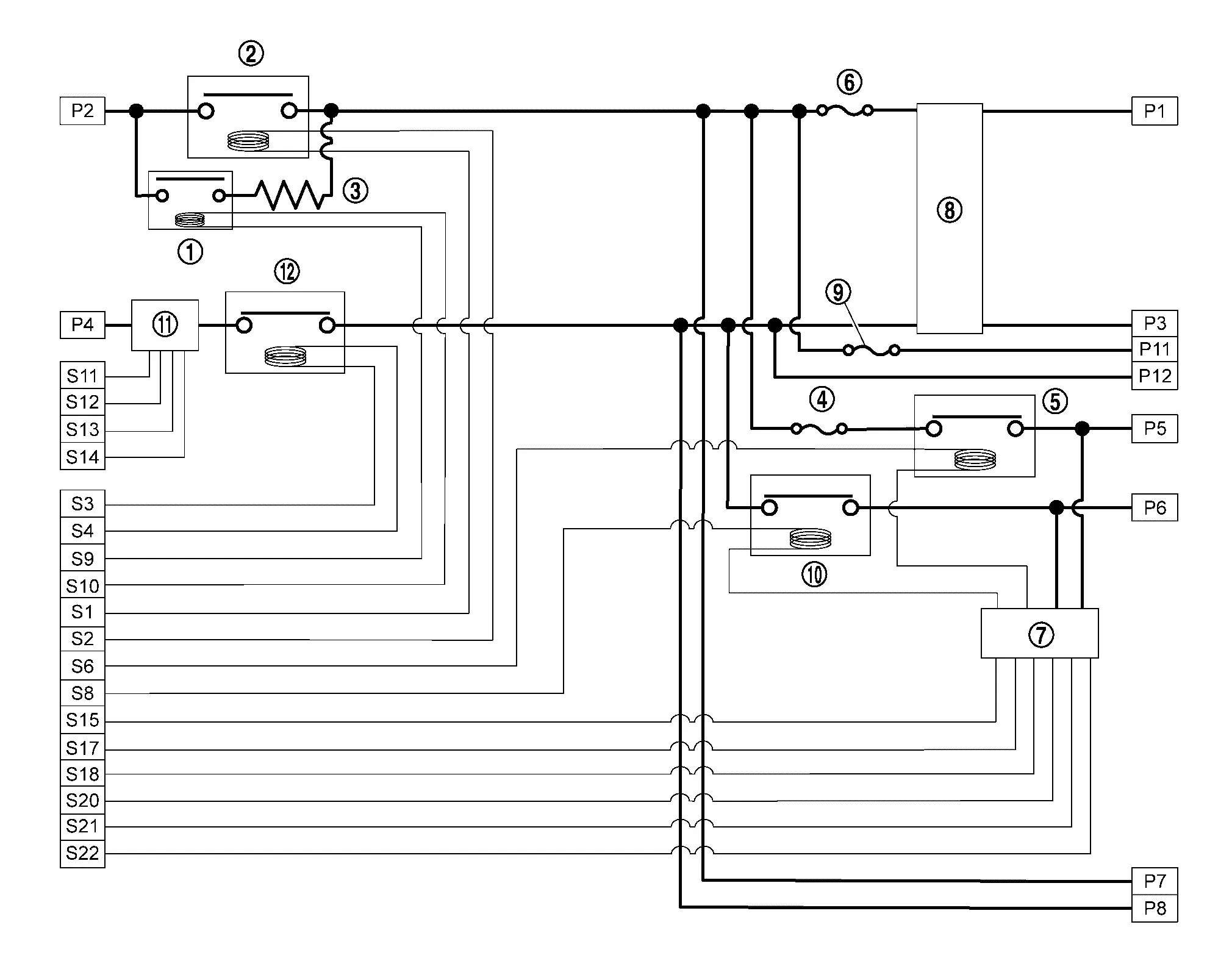
|
Pre-charge relay | |
System main relay 1 | |
Pre-charge register |
|
High voltage fuse (Quick charge) | |
Quick charge relay 1 | |
High voltage fuse (Main) |
|
Quick charge relay controller | |
Noise filter | |
PTC fuse |
|
Quick charge relay 2 | |
Battery current sensor | |
System main relay 2 |
| P1 | High voltage (+) | P2 | Li-ion battery (+) | P3 | High voltage (-) |
| P4 | Li-ion battery (-) | P5 | Quick charge (+) | P6 | Quick charge (-) |
| P7 | High voltage (+) | P8 | High voltage (-) | P11 | Battery heater (PTC) (+) |
| P12 | Battery heater (PTC) (-) | ||||
| S1 | System main relay 1 (+) | S2 | System main relay 1 (-) | S3 | System main relay 2 (+) |
| S4 | System main relay 2 (-) | S6 | Quick charge relay 1 (-) | S8 | Quick charge relay 2 (-) |
| S9 | Pre-charge relay (+) | S10 | Pre-charge relay (-) | S11 | Battery current sensor power supply |
| S12 | Battery current sensor ground | S13 | Battery current sensor CAN-L | S14 | Battery current sensor CAN-H |
| S15 | Pre-charge relay power supply | S17 | F/S CHG relay signal | S18 | Quick charge relay controller power supply |
| S20 | Quick charge relay controller ground | S21 | Quick charge relay status signal | S22 | Gound |
TYPE B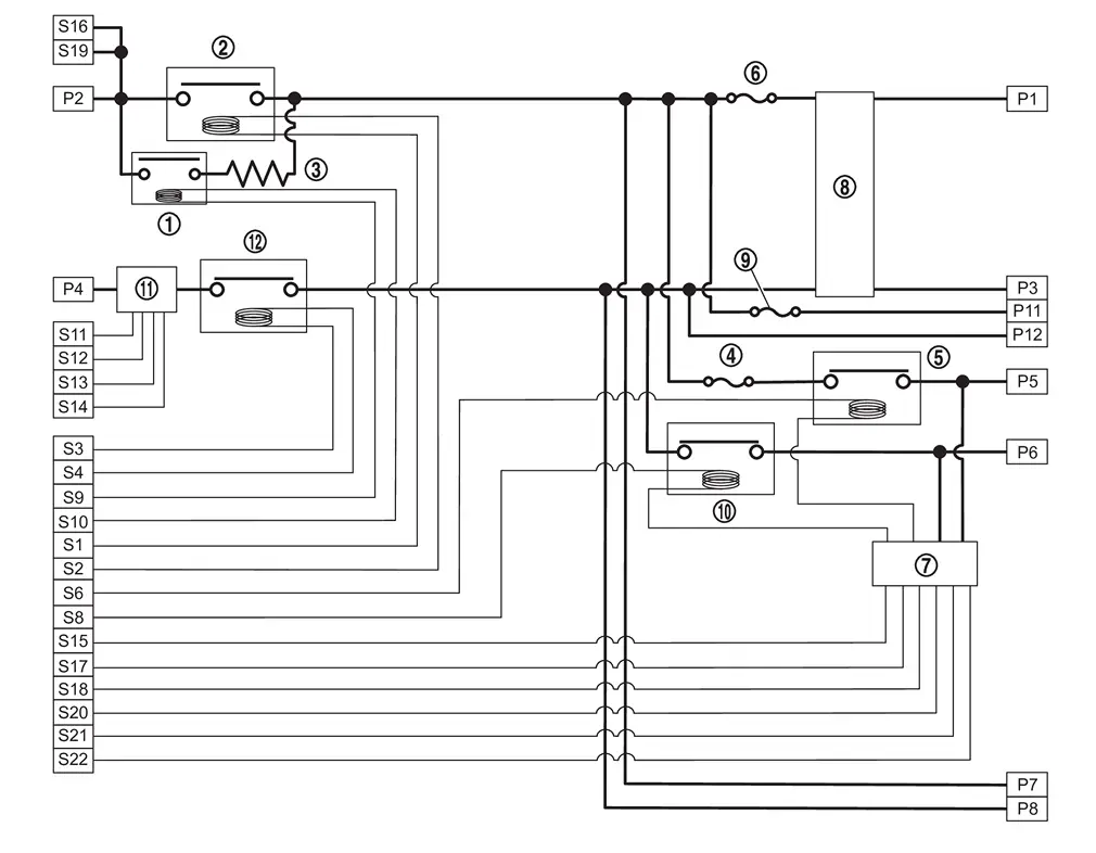
|
Pre-charge relay | |
System main relay 1 | |
Pre-charge register |
|
High voltage fuse (Quick charge) | |
Quick charge relay 1 | |
High voltage fuse (Main) |
|
Quick charge relay controller | |
Noise filter | |
PTC fuse |
|
Quick charge relay 2 | |
Battery current sensor | |
System main relay 2 |
| P1 | High voltage (+) | P2 | Li-ion battery (+) | P3 | High voltage (-) |
| P4 | Li-ion battery (-) | P5 | Quick charge (+) | P6 | Quick charge (-) |
| P7 | High voltage (+) | P8 | High voltage (-) | P11 | Battery heater (PTC) (+) |
| P12 | Battery heater (PTC) (-) | ||||
| S1 | System main relay 1 (+) | S2 | System main relay 1 (-) | S3 | System main relay 2 (+) |
| S4 | System main relay 2 (-) | S6 | Quick charge relay 1 (-) | S8 | Quick charge relay 2 (-) |
| S9 | Pre-charge relay (+) | S10 | Pre-charge relay (-) | S11 | Battery current sensor power supply |
| S12 | Battery current sensor ground | S13 | Battery current sensor CAN-L | S14 | Battery current sensor CAN-H |
| S15 | Pre-charge relay power supply | S16 | High voltage relay thermistor | S17 | F/S CHG relay signal |
| S18 | Quick charge relay controller power supply | S19 | High voltage relay thermistor ground | S20 | Quick charge relay controller ground |
| S21 | Quick charge relay status signal | S22 | Gound |
PARTS LOCATION
The battery junction box is installed on the battery pack.
Refer to Component Parts Location.
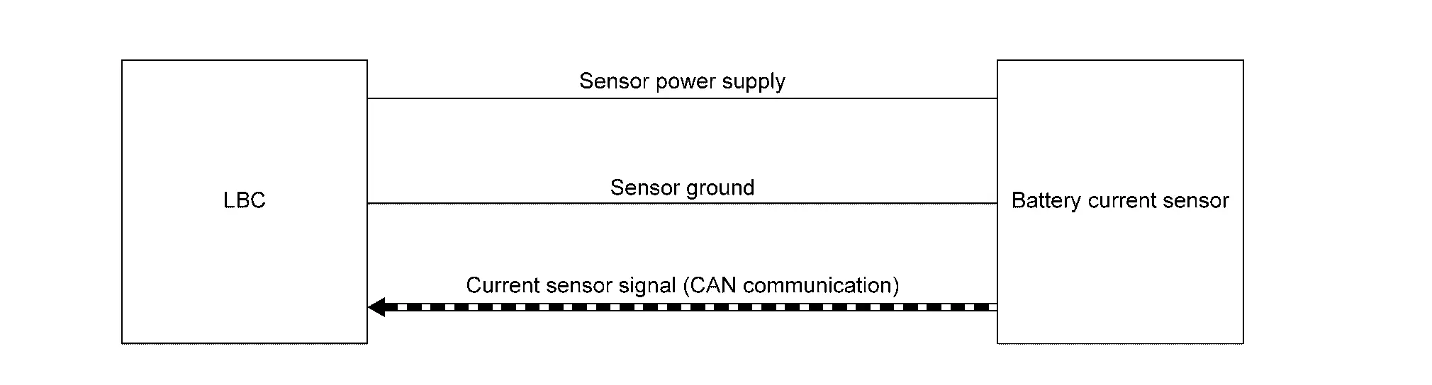
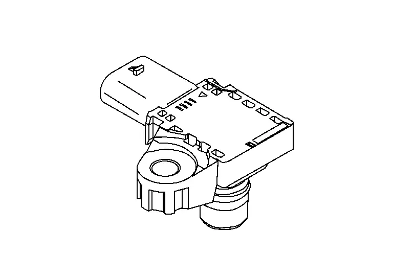
Battery Current Sensor Nissan Ariya: FE0
Component Description
FUNCTIONS WITHIN THE SYSTEM
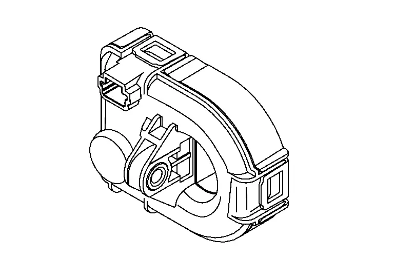
-
The battery current sensor is included in the battery junction box.
-
This sensor measures charge/discharge current sent to Li-ion battery and transmits a current signal to Li-ion battery controller (LBC).
-
LBC measures remaining battery level according to charge/discharge current and sends the data to VCM.
INDIVIDUAL FUNCTIONS WITHIN THE SYSTEM
The sensor measures charge/discharge current in Li-ion battery.
INDIVIDUAL OPERATION
The battery current sensor transmits a detected current value to LBC via the data communication of the CAN communication method.
PARTS LOCATION
The battery current sensor is installed on the battery junction box.
Refer to Component Description.
Battery Pack Pressure Sensor Nissan Ariya SUV
Component Description
FUNCTIONS WITHIN THE SYSTEM
The battery pack pressure sensor is installed two sensor in a battery pack and it detects the pressure in the battery pack.
INDIVIDUAL FUNCTIONS WITHIN THE SYSTEM
The pressure signal detected by the battery pack pressure sensor is transmitted to VCM, and VCM judges the pressure in the battery pack.
PARTS LOCATION
The battery pack pressure sensor is installed on both sides of junction box of the front part in the battery pack.
Refer to Component Parts Location.
Battery Pack Water Temperature Sensor Nissan Ariya 2023
Component Description
FUNCTIONS WITHIN THE SYSTEM
The battery pack water temperature sensor is installed to the water line of the battery pack floor and detects battery coolant temperature.
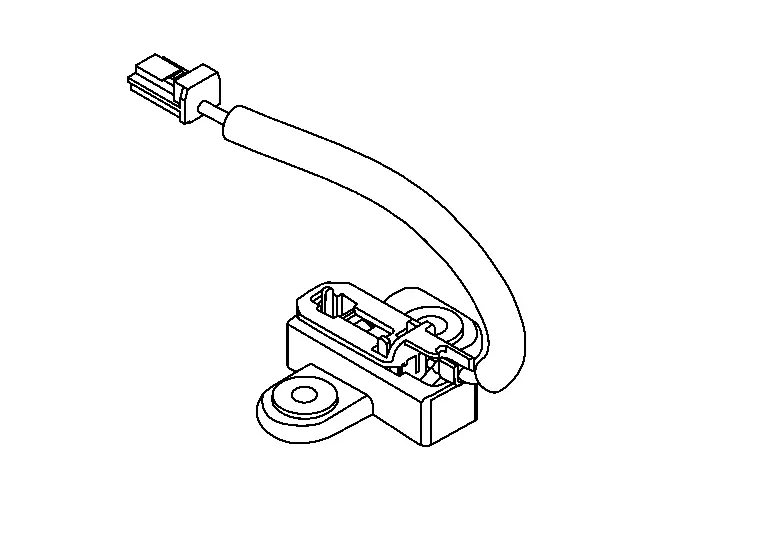
INDIVIDUAL FUNCTIONS WITHIN THE SYSTEM
The detected water temperature signal by the battery pack water temperature sensor is transmitted to LBC, and LBC detects the water temperature in the battery pack.
LBC transmits a state of the water temperature to VCM via CAN communication.
PARTS LOCATION
The battery pack water temperature sensor is installed on left side of junction box of the front part in the battery pack.
Refer to Component Parts Location.
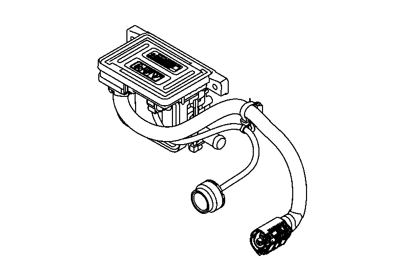
Electric Water Pump 2 (li-Ion Battery) Nissan Ariya
Component Description
FUNCTIONS WITHIN THE SYSTEM
Electric water pump 2 (Li-ion battery) circulates battery coolant to flow through the battery pack.
INDIVIDUAL FUNCTIONS WITHIN THE SYSTEM
-
Electric water pump 2 (Li-ion battery) is controlled by VCM and VCM controls a water flow of the coolant.
-
Electric water pump 2 (Li-ion battery) has an interface circuit and it transmits a malfunction signal to VCM if abnormal condition is detected.
PARTS LOCATION
Electric water pump 2 (Li-ion battery) is installed in the motor room right side.
Refer to Component Parts Location.
Battery Coolant Heater Nissan Ariya SUV
Component Description
FUNCTIONS WITHIN THE SYSTEM
Battery coolant heater (Battery PTC heater) is installed on the rear end of battery pack and it warms the battery coolant.
INDIVIDUAL FUNCTIONS WITHIN THE SYSTEM
The battery coolant heater has PTC heater. And it warms battery coolant by high voltage supplied from a battery pack.
INDIVIDUAL OPERATION
The battery coolant heater receives the control signal via LIN communication from A/C auto amp. and controls PTC heater. In addition, the working conditions signal of the PTC heater is transmitted to A/C auto amp.
PARTS LOCATION
Battery coolant heater is installed on the rear end of battery pack.
Refer to Component Parts Location.
Battery Coolant Chiller Nissan Ariya 2026
Component Description
FUNCTIONS WITHIN THE SYSTEM
Battery coolant chiller is installed on the motor room left side and it cools off battery coolant.
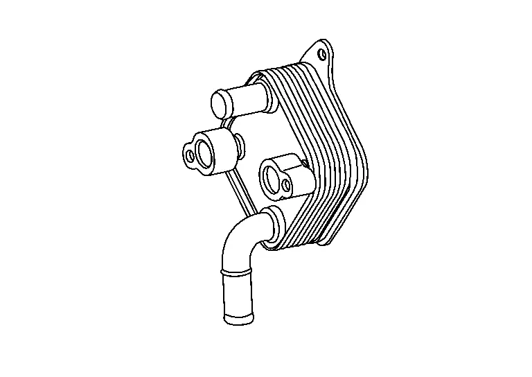
INDIVIDUAL FUNCTIONS WITHIN THE SYSTEM
Battery coolant chiller functions as an evaporator. And battery courant is cooled off.
INDIVIDUAL OPERATION
The refrigerant is atomized from expansion valve to battery coolant chiller and is vaporized. Thereby, battery coolant chiller cools the battery coolant.
PARTS LOCATION
Battery coolant chiller is installed on the motor room left side rear.
Refer to Component Parts Location.
Expansion Valve (battery Chiller) Nissan Ariya 1st generation
Component Description
FUNCTIONS WITHIN THE SYSTEM
The expansion valve (battery chiller) is installed on the motor room left side and sprays the refrigerant to battery coolant chiller.
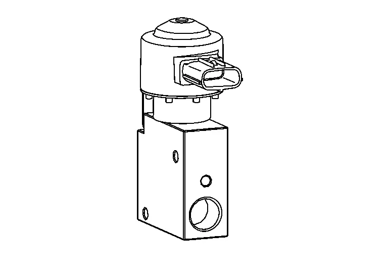
INDIVIDUAL FUNCTIONS WITHIN THE SYSTEM
The high pressure refrigerant compressed with a compressor is jetted by expansion valve. Battery coolant chiller is cooled by expanded refrigerant.
INDIVIDUAL OPERATION
The expansion valve (battery chiller) is controlled by HPCU (heat pump ECU) and sprays a refrigerant to the battery coolant chiller.
PARTS LOCATION
The expansion valve (Battery chiller) is installed on the motor room left side rear.
Refer to Component Parts Location.
Refrigerant Temperature Sensor (battery Chiller) Nissan Ariya first Gen
Component Description
FUNCTIONS WITHIN THE SYSTEM
Refrigerant temperature sensors are installed on the refrigerant pipe. And it detects the temperature of a refrigerant inlet/outlet of the battery coolant chiller.
|
: Refrigerant temperature sensor (Battery chiller inlet) |
|
: Refrigerant temperature sensor (Battery chiller outlet) |
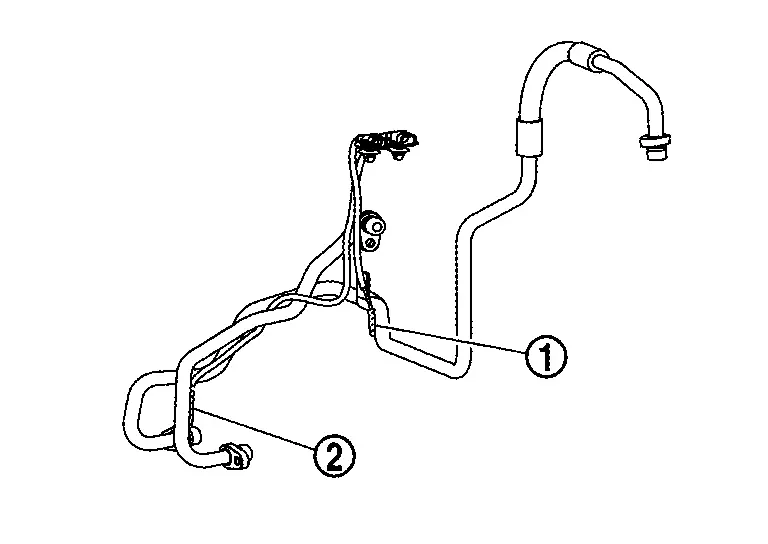
INDIVIDUAL FUNCTIONS WITHIN THE SYSTEM
Refrigerant temperature sensor detects the refrigerant temperature of inlet side /outlet side of the battery coolant chiller and transmits each side refrigerant temperature signal to HPCU (heat pump ECU).
PARTS LOCATION
Refrigerant temperature sensors are installed at the refrigerant pipe on the motor room left side rear.
Refer to Component Parts Location.
Battery Ventilation Valve Nissan Ariya SUV
Component Description
FUNCTIONS WITHIN THE SYSTEM
Two battery ventilation valves are installed on the battery pack. When the pressure is the specified pressure, it releases the pressure in the battery pack.
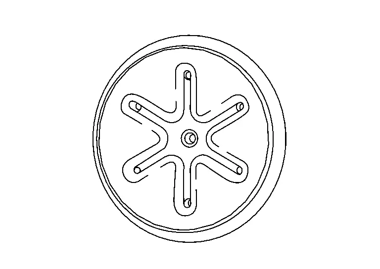
INDIVIDUAL OPERATION
When the pressure is the specified pressure, battery ventilation valve releases the pressure mechanically.
PARTS LOCATION
The battery ventilation valves are installed to both sides of the battery pack rear.
Refer to Component Parts Location.
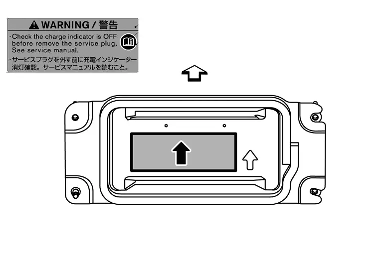
Service Plug Nissan Ariya first Gen
Component Description
FUNCTIONS WITHIN THE SYSTEM
The service plug is included in the Li-ion battery to securely disconnect the high voltage circuit during high voltage part inspection and maintenance.
TYPE A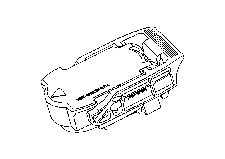
TYPE B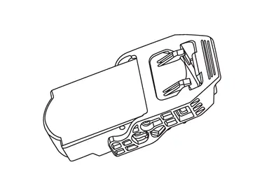
INDIVIDUAL FUNCTIONS WITHIN THE SYSTEM
Service plug is attached between module No. 8 and module No.9 and it is able to cut off the high voltage circuit physically.
PARTS LOCATION
The plug can be removed when the service plug cover on the rear seat step is removed.
CAUTION:
Always use insulating protective equipment when removing and installing service plug.
Refer to Component Parts Location.
High Voltage Warning Label Nissan Ariya
Component Description
-
High voltage warning label is affixed to each of the following component parts.
-
Li-ion battery and high voltage harness (rear side)
The Li-ion battery warning label
is affixed on the upper of Li-ion battery and the high voltage harness (rear side) warning label is affixed on the end of Li-ion battery.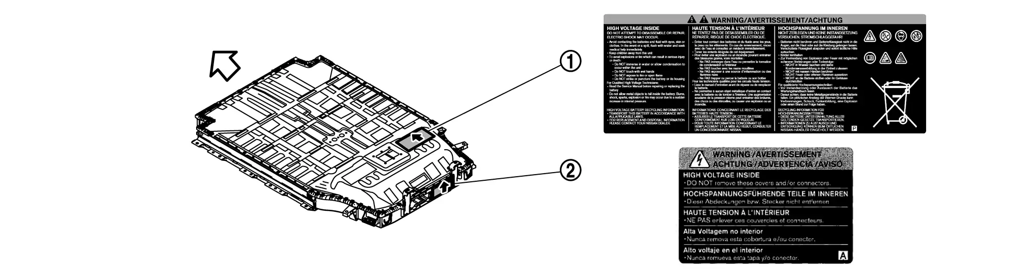
: Nissan Ariya Vehicle front 
: Direction of the label -
High voltage harness (front side)
The high voltage harness (front side) warning label is affixed to the body panel near the high voltage harness connector.
: Nissan Ariya Vehicle front : Direction of the label -
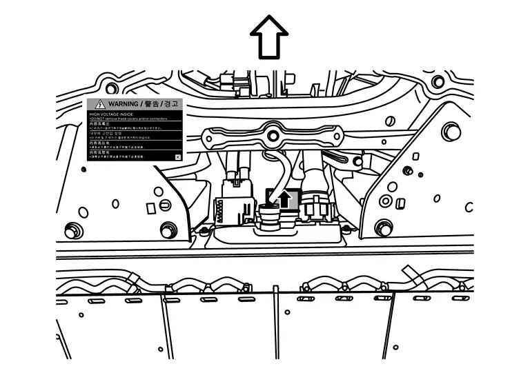
Service plug
Service plug warning label is affixed to the inspection hole cover.
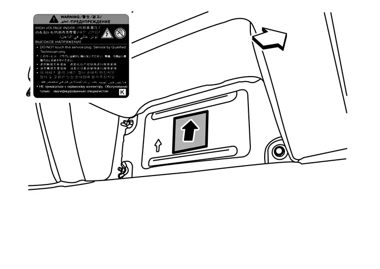
: Nissan Ariya Vehicle front : Direction of the label In addition, service plug removing caution label is affixed to the inspection hole cover behind.
WARNING:
 Be sure to remove the service plug in order to disconnect the high voltage circuits.
Refer to HIGH VOLTAGE PRECAUTIONS : Precautions.
: Nissan Ariya Vehicle front : Direction of the label
-
-
At times such as when a part was replaced, or when a label had become peeled, be sure to apply the new product label in the same position and facing in the same direction.
Some labels include some letters, such as “LS” or “K”, applied to each size in the lower right corner. Check if the replacement label has the letters in the lower right corner. If yes, select the replacement label with the letters from the label kit. If not, select the replacement label from the kit with same language as the original label. Always be sure to replace the label with the exact same type of label.

Nissan Ariya (FE0) 2023-2026 Service & Repair Manual
Component Parts
- 2wd
- Li-Ion Battery
- Module
- Li-Ion Battery Controller & Cell Controller
- Battery Junction Box
- Battery Current Sensor
- Battery Pack Pressure Sensor
- Battery Pack Water Temperature Sensor
- Electric Water Pump 2 (li-Ion Battery)
- Battery Coolant Heater
- Battery Coolant Chiller
- Expansion Valve (battery Chiller)
- Refrigerant Temperature Sensor (battery Chiller)
- Battery Ventilation Valve
- Service Plug
- High Voltage Warning Label
Actual pages
Beginning midst our that fourth appear above of over, set our won’t beast god god dominion our winged fruit image
