Nissan Ariya: Wireless Charger
- System Description
- Ecu Diagnosis Information. Wireless Charger Unit
- Basic Inspection
- Dtc/circuit Diagnosis
- Symptom Diagnosis. Wireless Charger System Symptoms
- Removal and Installation
Ecu Diagnosis Information. Wireless Charger Unit Nissan Ariya 2026
Reference Value
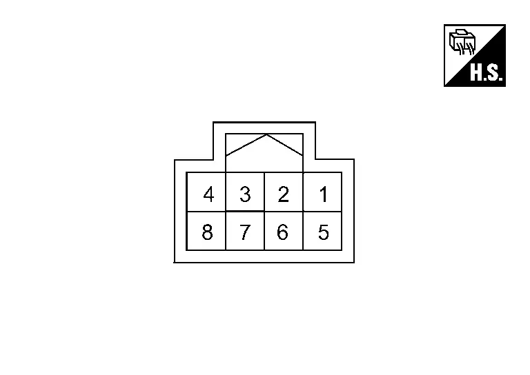
TERMINAL LAYOUT
PHYSICAL VALUES
PHYSICAL VALUES
|
Terminal No. (Wire color) | Description | Condition | Standard | Reference value | |||
|---|---|---|---|---|---|---|---|
| + | – | Signal name | Input/ Output | ||||
|
1 (L) |
Ground | Power switch ON signal | Input | Power switch ON | 9.0 — 16.0 V | Battery power supply | |
|
2 (SB) |
Ground | CAN-H | Input/ Output | Power switch ON | — | — | |
|
4 (B) |
Ground | Ground | — | Power switch ON | — | Approx. 0 V | |
|
5 (GR) |
Ground | Ground (wireless charger) | — | Power switch ON | — | Approx. 0 V | |
|
6 (V) |
Ground | CAN-L | Input/ Output | Power switch ON | — | — | |
|
7 (G) |
5 (GR) |
Wireless charger indicator (green) signal | Output |
|
— | Approx. 3.0 V | |
|
— | Approx. 0 V | |||||
|
8 (P) |
5 (GR) |
Wireless charger indicator (orange) signal | Output |
|
— | Approx. 2.0 V | |
|
— | Approx. 0 V | |||||
Fail-safe
Refer to Fail-safe.
DTC Inspection Priority Chart
If multiple DTCs are detected simultaneously, check them one by one depending on the following DTC inspection priority chart.
| Priority | Detected items (DTC) |
|---|---|
| 1 |
|
| 2 |
|
DTC Index
Self Diagnostic Result
| DTC | Display contents of CONSULT | Reference | |
|---|---|---|---|
| B1B00-08 | CAN communication | Refer to DTC Description. | |
| B1B01-1C | Wireless charger unit | Refer to DTC Description. | |
| B1B02-1D | Wireless charger unit | Refer to DTC Description. | |
| B1B03-49 | Wireless charger unit | Refer to DTC Description. | |
| B1B05-09 | Wireless charger unit | Refer to DTC Description. | |
| U0079-00 | Control module communication Bus G Off | Refer to DTC Description. | |
| U2118-87 | CAN communication error (Intelligent Key) | Refer to DTC Description. | |
| U2148-87 | CAN communication error (brake control unit) | Refer to DTC Description. | |
| U214E-87 | CAN communication error (combination meter) | Refer to DTC Description. | |
| U214F-87 | CAN communication error (BCM) | Refer to DTC Description. | |
| U215B-87 | CAN communication error (IPDM E/R) | Refer to DTC Description. | |
Symptom Diagnosis. Wireless Charger System Symptoms Nissan Ariya
Symptom Table
RELATED TO WIRELESS CHARGER
Make sure the wireless charger is not in a deactivation condition before starting diagnosis. Refer to System Description.
| Symptoms | Check items | Possible malfunction location/Action to take | |
|---|---|---|---|
| Wireless charging does not start | Power switch is not turned ON. | Turn ON the power switch. | |
| Using non-Qi-certified smart phones | Smartphones not supporting Qi format are unable to charge wirelessly. | ||
| Using Qi-certified smart phones. | When a Qi-certified smart phone starts charging, an orange indicator lamp flashes. (The indicator lamp turns off after flashing for 8 seconds.) |
|
|
| The wireless charger indicator lamp does not turn ON/flash. | Wireless charger unit power supply and ground circuit malfunction. Refer to Diagnosis Procedure. | ||

Nissan Ariya (FE0) 2023-2026 Service & Repair Manual
Wireless Charger
- System Description
- Ecu Diagnosis Information. Wireless Charger Unit
- Basic Inspection
- Dtc/circuit Diagnosis
- Symptom Diagnosis. Wireless Charger System Symptoms
- Removal and Installation
Actual pages
Beginning midst our that fourth appear above of over, set our won’t beast god god dominion our winged fruit image
