Nissan Ariya: System
- Vehicle Charging System
- Normal Charge Control
- Quick Charge Control
- Automatic 12v Battery Charge Control
- Charge Port Control
- Li-Ion Battery Charge Control
- Power Voltage Variable Control System
- Remove Charge Connector Warning
Vehicle Charging System Nissan Ariya 2026
System Description
System diagram
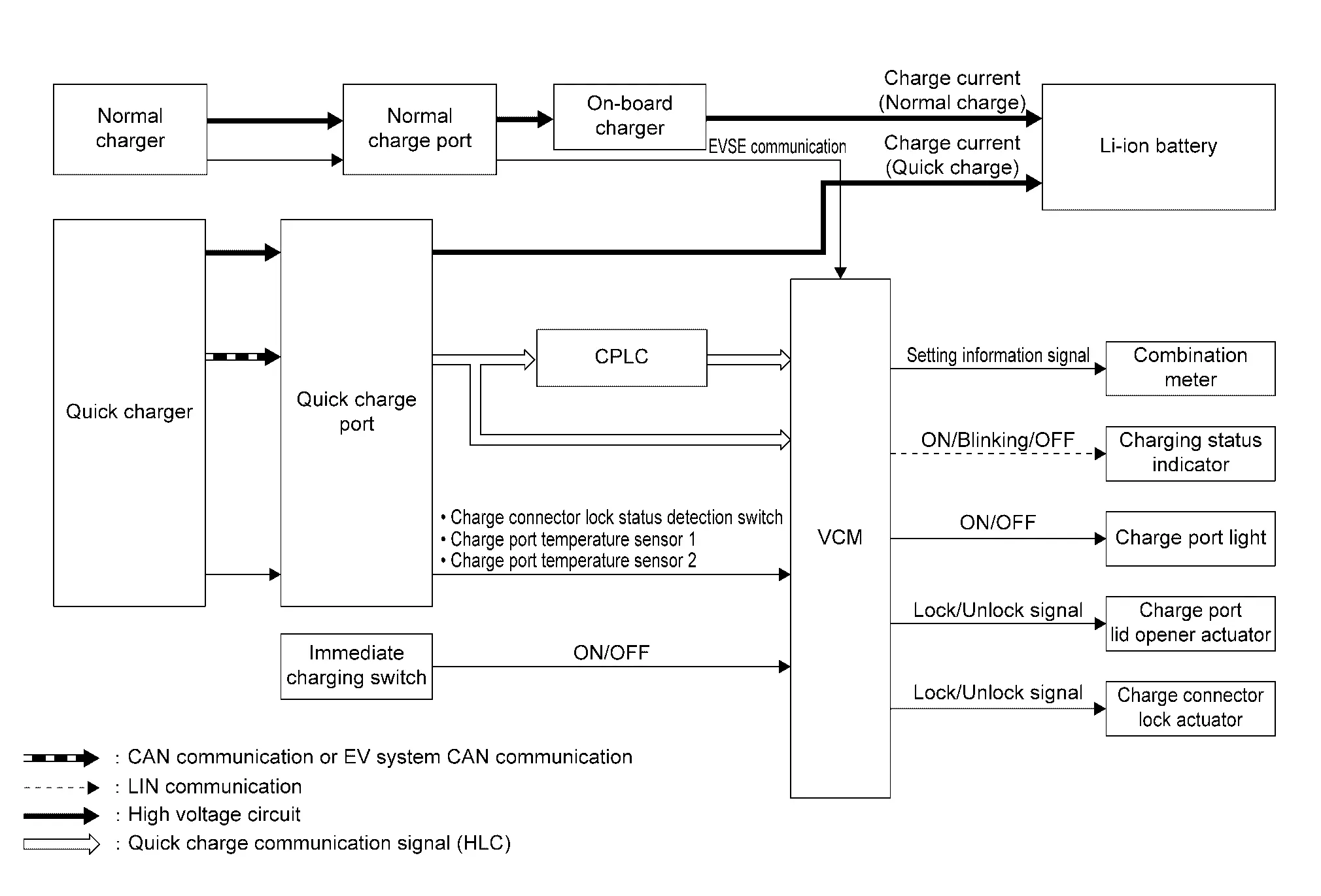
| Component | Function |
|---|---|
| On-board charger | Refer to Component Description. |
| VCM |
Control related to Nissan Ariya vehicle charging system is integrated. For detail Refer to Component Description. |
| CPLC | Refer to Component Description. |
| Combination meter | Charge connector lock system setting can be changed |
| EVSE (Charge cable) | Refer to Component Description (120V/240V EVSE) or Component Description (120V EVSE). |
| Charging status indicator | Refer to Component Description. |
| Immediate charging switch | Refer to Component Description. |
| Charge port | Refer to Component Description. |
| Charge port light | Refer to Component Description. |
| Charge connector lock actuator | Refer to Component Description. |
| Charge port lid opener actuator |
Charge port lid is unlocked according to operation signal from VCM For detail Refer to Charge Port Lid Actuator. |
DESCRIPTION
Vehicle charging system is mainly controlled by VCM.
| Item | Description | Reference page |
|---|---|---|
| Li-ion battery charge control | Automatically selects a charge mode that is suitable for the external power source and controls Li-ion battery charging. | Refer to System Description. |
| Charge port control | VCM performs comprehensive control to improve efficiency of charge work. | Refer to System Description. |
| Variable voltage control system | DC/DC converter output is changed according to command from VCM | Refer to System Description. |
| Automatic 12V battery charge control | DC/DC converter controlled by VCM command and 12 V battery is charged. | Refer to System Description. |
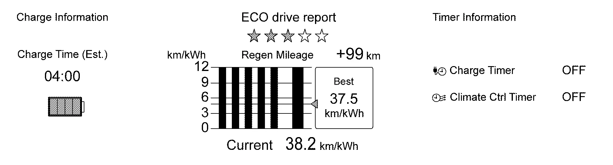
Setting information of vehicle charging system can be checked on "Vehicle information" screen of information display in combination meter.
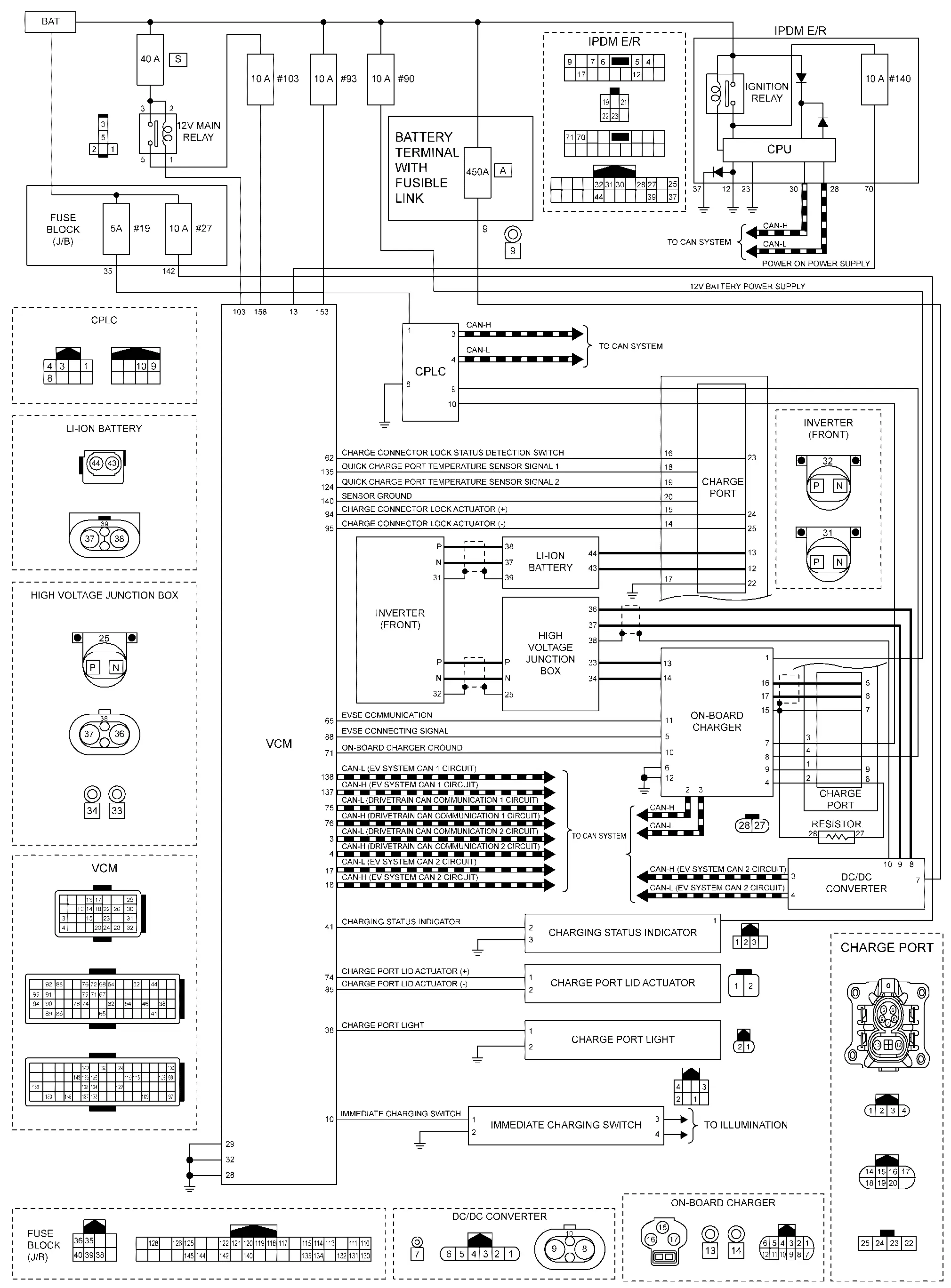
Circuit Diagram
Fail-safe
ON-BOARD CHARGER
| CONSULT display | Fail safe operation |
|---|---|
| P0D22-00 | Normal charge is stopped |
| P0D2A-00 | |
| P0D3A-00 | |
| P0D3B-00 | |
| P0D3F-00 | |
| P0D40-00 | |
| P0D4E-00 | |
| P0D4F-00 | |
| P0D53-00 | |
| P0D54-00 | |
| P0D67-00 | |
| P0D85-00 | |
| P0E5E-00 | |
| P1C50-43 | |
| P1C50-4B | Normal charge is paused |
| P1C60-19 | Normal charge is stopped |
| P1C61-82 | |
| P1C62-82 | |
| P1C63-97 | |
| P1C64-17 | |
| P1C64-38 | |
| U1D40-87 | |
| U2143-83 | |
| U2143-87 | |
| U2144-83 | |
| U2A0F-88 |
CPLC
| CONSULT display | Fail safe operation |
|---|---|
| B2B01-87 | Quick charge is stopped |
| B2B02-87 | |
| B2B0C-68 | |
| B2B0D-68 | |
| B2B0E-68 | |
| B2B0F-68 | |
| B2B10-68 | |
| B2B11-68 | |
| B2B12-68 | |
| B2B13-68 | |
| B2B15-68 | |
| B2B17-68 | |
| B2B18-68 | |
| B2B19-68 | |
| B2B1A-68 | |
| B2B1C-68 | |
| B2B1D-87 | |
| B2B1E-68 | |
| B2B1F-04 | |
| U0079-00 | |
| U2143-87 | |
| U214F-87 |
DC/DC converter
| CONSULT display | Fail safe operation |
|---|---|
| P1AA8-A2 | DC/DC converter output is stopped |
| P1AA8-A3 | |
| P1AA9-64 | DC/DC converter output current is stopped |
| P1AAA-64 | |
| P1AAB-18 | |
| P1AAB-19 | |
| P1AAB-64 | |
| P1AAC-18 | |
| P1AAC-19 | |
| P1AAC-64 | |
| P1AAD-48 | DC/DC converter output is stopped |
| P1AAE-31 | DC/DC converter output current is stopped |
| P1AAE-39 | |
| P1AAE-3A | |
| P1AAE-4B | |
| P1AAF-31 | |
| P1AAF-39 | |
| P1AAF-3A | |
| P1AAF-4B | |
| P1AB0-64 | |
| P1AB2-16 | DC/DC converter output is stopped |
| P1AB2-17 | |
| P1AB2-48 | |
| P1AB2-64 | |
| P1AB5-64 | |
| P1AB9-4B | DC/DC converter output is stopped |
| P1ABA-16 | |
| P1ABA-17 | |
| P1ABB-17 | |
| P1ABB-48 | |
| P1ABC-16 | |
| P1ABC-17 | |
| P1ABD-19 | DC/DC converter output current is stopped |
| P1ABE-19 | |
| P1ABF-05 | DC/DC converter output is stopped |
| P1AC1-F0 | DC/DC converter output current is stopped |
| P1AC1-F1 | |
| P1AC1-F2 | |
| P1AC1-F3 | |
| P1AC1-F4 | DC/DC converter output is stopped |
| P1AC2-48 | |
| P1AC3-F2 |
DC/DC converter output current is limited.
When P1AC3-F2 and P1AC3-F3 are detected at the same time, DC/DC converter output is stopped. |
| P1AC3-F3 | |
| U1D50-88 | DC/DC converter output voltage is fixed. |
| U2143-F1 |
|
| U2143-F5 | DC/DC converter output voltage is fixed. |
| U2143-F7 |
|
| U2143-FB | DC/DC converter output voltage is fixed. |
| U2143-FC | |
| U2143-FD |
|
| U2A0F-88 | DC/DC converter output voltage is fixed. |
Warning/Indicator/Chime list
WARNING LAMP / INDICATOR LAMP
| Item | Location/Function |
|---|---|
| Plug in indicator lamp | For location, Refer to Design. |
| For function, Refer to Plug In Indicator Lamp. |
WARNING LAMP / INDICATOR LAMP (VEHICLE INFORMATION DISPLAY)
| Item | Location/Function |
|---|---|
| Remove charge connector warning | Refer to System Description. |
Handling Precaution
HANDLING OF CHARGE CABLE, CHARGE PORT, AND CHARGE CONNECTOR
-
Never touch metal terminals of the charge port or the charge connector.
-
Never modify or disassemble control box, socket, charge cable, charge connector, or charge port.
-
Never apply excessive force to the charge cable.
-
Never pull.
-
Never twist.
-
Never drag.
-
Never place a heavy item on charge cable.
-
Never place near a heating device (heater, etc.).
-
-
Never drop or subject to strong impact.
-
When storing, be sure to attach the cap to the connector before storing.
-
When storing, store in a location away from direct sunlight, not exposed to rain or wind, and where dust and dirt do not enter.
-
Use only with a designated socket especially wired for EV/PHEV with NISSAN recommended work or equivalent means. (This is because there is an extremely high risk of electric shock if the ground line is connected incorrectly.)
-
Never allow the control box to be submerged in water.
-
If you have a pacemaker or implantable cardioverter-defibrillator (ICD) implant, keep a distance of at least 15 cm between you and the EVSE control box.
PRECAUTIONS FOR CHARGING
-
Use genuine NISSAN charge cables only.
-
Never use an extension cord or conversion adapter except genuine NISSAN adapter and exchangeable plug.
-
Be sure to use an independent specification current or higher charging station or socket.
Charge cable Specification current 120V EVSE (L1) 12A 120V/240V EVSE with 120V outlet (L1/L2) 12A 120V/240V EVSE with 240V outlet (L1/L2) 30A Charging device According to the charging device operation manual. -
Never touch the plug, genuine NISSAN adapter or exchangeable plug with wet hands.
-
If the male terminal of EVSE plug, genuine NISSAN adapter or exchangeable plug is dirty or wet, wipe it with a clean, dry cloth.
-
If the female terminal of genuine NISSAN adapter or exchangeable plug is dirty or wet, clean it with an air blow gun.
-
Check that there is no foreign material such as water or dust in the charge port, charge connector, genuine NISSAN adapter or exchangeable plug.
WARNING:
-
 Since there may be a risk of electric shock, never touch the charge connector, charge port, genuine NISSAN adapter or exchangeable plug if they contain foreign material.
 -
Since there may be a risk of electric shock or electric leakage, never connect the charge connector, charge port, genuine NISSAN adapter or exchangeable plug if they contain foreign material.
-
-
Never use the charge cable if it is worn, or if there are any deep scratches or other damage where the core wires are visible.
-
Never use the EVSE charge connector, control box, plug, genuine NISSAN adapter or exchangeable plug if it is broken, scratched, cracked, or otherwise damaged.
-
Check that there is no rust, corrosion, or damage on the charge port, charge connector, genuine NISSAN adapter or exchangeable plug. Check that there is no loosening at the time of connection.
WARNING:
Since electric leakage, electric shock, short-circuit, or fire may occur, never charge if any malfunction is found. -
Never perform charging when the connection is heavily exposed to water.
-
Never perform charging with the body cover attached.
-
Never perform charging when there may be a risk of lightning.
-
Stop charging immediately when an unusual odor or smoke is found during charging.
-
Never place hand near the cooling fan during charging.
 NOTE:
NOTE:
The cooling fan may automatically start operation during charging when the power switch is turned OFF.
-
After charging, securely close the cover and lid of the charge port to prevent entry of water or dust.
-
To turn on READY after charging, operate after disconnecting the charge connector from the charge port.
NOTE:
When the charge connector is connected to the charge port, READY is disabled.
-
To prevent electric shock or fire arising from electric leakage, use a waterproof plug with grounding connected to the ground fault interrupter.
-
Never connect to a socket providing other than the rated voltage.
WARNING:
If electric outlet with a low current rating is used or if multi-outlets installed and used in combination with another device, electric outlet may cause the breaker down, abnormal heating or resulting in a fire.
-
For charging, never use a generator or any other power source other than specified.
NOTE:
Charging may not be performed correctly or a malfunction may occur.
-
When quick charging is performed, be sure to use a quick charger compatible with the Nissan Ariya vehicle.
EVSE
WARNING:
-
Precautions on the electrical outlet
-
Use a grounded electrical outlet that complies with standards and regulations.
-
Do not use an electrical outlet if the Plug is loose when inserted in the outlet or if there is damage or corrosion on the outlet side.
-
Before you connect the EVSE be sure to check the rated current shown on the EVSE to ensure that the outlet and circuit has enough current capacity to charge your Nissan Ariya vehicle safely.
-
The EVSE draws a constant 12 A with 120 V outlet or 30 A with 240 V outlet, you must ensure that the outlet and household wiring used for charging is rated at this level and complies with the latest electrical wiring standard and regulations in your country or area.
-
If in any doubt about the outlet and circuit, consult a qualified electrician.
CAUTION:
-
Be sure to connect the EVSE to an outlet with the rated voltage only.
-
The Control Box will become hot while the EVSE is charging. This is not a malfunction.
Charging device
WARNING:
Be sure to follow the precautions for using the charging device that can be installed in your home. Failing to do so could result in serious injury or death.
Normal Charge Control Nissan Ariya 2023
System Description
System Diagram
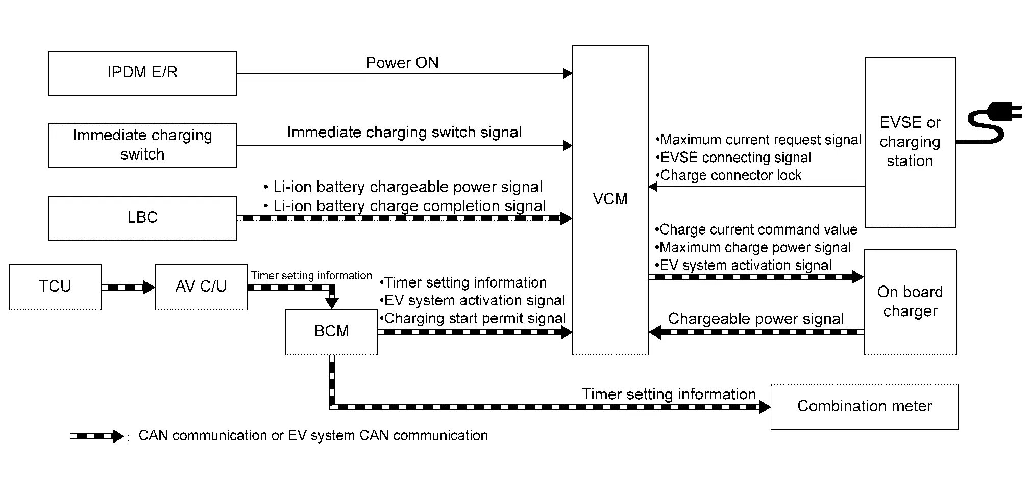
| Component parts | Function |
|---|---|
| VCM | Controls normal charge according to each signal |
| On-board charger |
Starts normal charge according to VCM command and supplies charge power to Li-ion battery. Refer to Component Description.for detail of function. |
| LBC | Transmits Li-ion battery status to VCM via CAN communication. |
| IPDM E/R | Supplies power ON power to VCM |
| TCU | Transmits timer set information to AV C/U |
| AV C/U |
|
| Immediate charging switch | Refer to Component Description. |
| EVSE | Refer to Component Description (120V/240V EVSE) or Component Description (120V EVSE). |
| Combination meter | When key switch is OFF, displays timer charge set information according to timer set information from BCM. |
| BCM | Transmits charge permit request or prohibit request to VCM via CAN communication according to timer charge set information |
BASIC CONTROL
When EVSE is connected at power switch OFF status, EVSE connection signal is transmitted to VCM. VCM that receives the signal determines as charging mode. VCM also determines the maximum charge power based on the Li-ion battery chargeable power signal received from LBC, the chargeable power signal received from on-board charger, and the maximum current request signal received from EVSE, and transmits the charge current command value to on-board charger determines the charge power based on charge current command value. VCM starts charge by turning ON the system main relays 1 and 2.
NOTE:
When shift position is except P range during READY status and charge connector is connected to charge port, READY is turned OFF and power switch is turned ON and then shift position is N range.
NORMAL CHARGE MODE
This mode performs charging by connecting EVSE (charge cable). Normal charge includes immediate charge mode, timer charge mode, and remote charge mode.
IMMEDIATE CHARGE MODE
This mode performs immediate charge as soon as EVSE is connected. If timer charge is not set, enter charge mode as soon as EVSE is connected. If timer charge is set, immediate charge mode is selected by pressing immediate charge switch.
-
When EVSE connection signal is transmitted to VCM, VCM judges that EVSE is connected and turns on-board charger ON to start charge immediately.
-
If timer is set, even when EVSE connection signal is transmitted to VCM, charge is not started immediately. If VCM detects immediate charge switch ON signal in this state, VCM judges as immediate charge mode and starts charge.
-
When the charge reaches specified amount and VCM receives Li-ion battery charge completion signal from LBC, VCM stops charge.
-
When pressing immediate charge switch, immediate charge is performed for 15 minutes. this mode does not reset even if charge connector is unplugged. To return to timer charge after pressing immediate charge switch, press immediate charge switch again during connecting charged connector.
TIMER MODE
BCM starts up automatically and starts charging at the set time.
NOTE:
Timer can be changed by "Timer charge" and "Timer charge at home/Timer charge 1/Timer charge 2/Timer charge 3"of navigation system.
| Item | Description |
|---|---|
| Timer charge 1, Timer charge 2, Timer charge 3 |
|
| Timer charge at home |
|
REMOTE CHARGE MODE
This mode starts the charge by remote control with mobile tool.
NOTE:
For operation, Refer to System Description.
-
When BCM transmits EV system activation request signal to VCM via CAN communication, VCM judges that remote charge mode is selected and starts charge.
-
When VCM receives Li-ion battery charge completion signal from LBC, VCM stops charge.
CANCEL CONDITIONS
VCM stops normal charge control when VCM detects that EVSE is disconnected.
In addition, when the following conditions are satisfied, VCM pauses normal charge and enters standby status.
-
When communication from EVSE and AC voltage are interrupted.
-
When EVSE connector release switch is ON.
-
When Li-ion battery temperature reaches the specified temperature or higher.
Quick Charge Control Nissan Ariya 2026
System Description
System Diagram
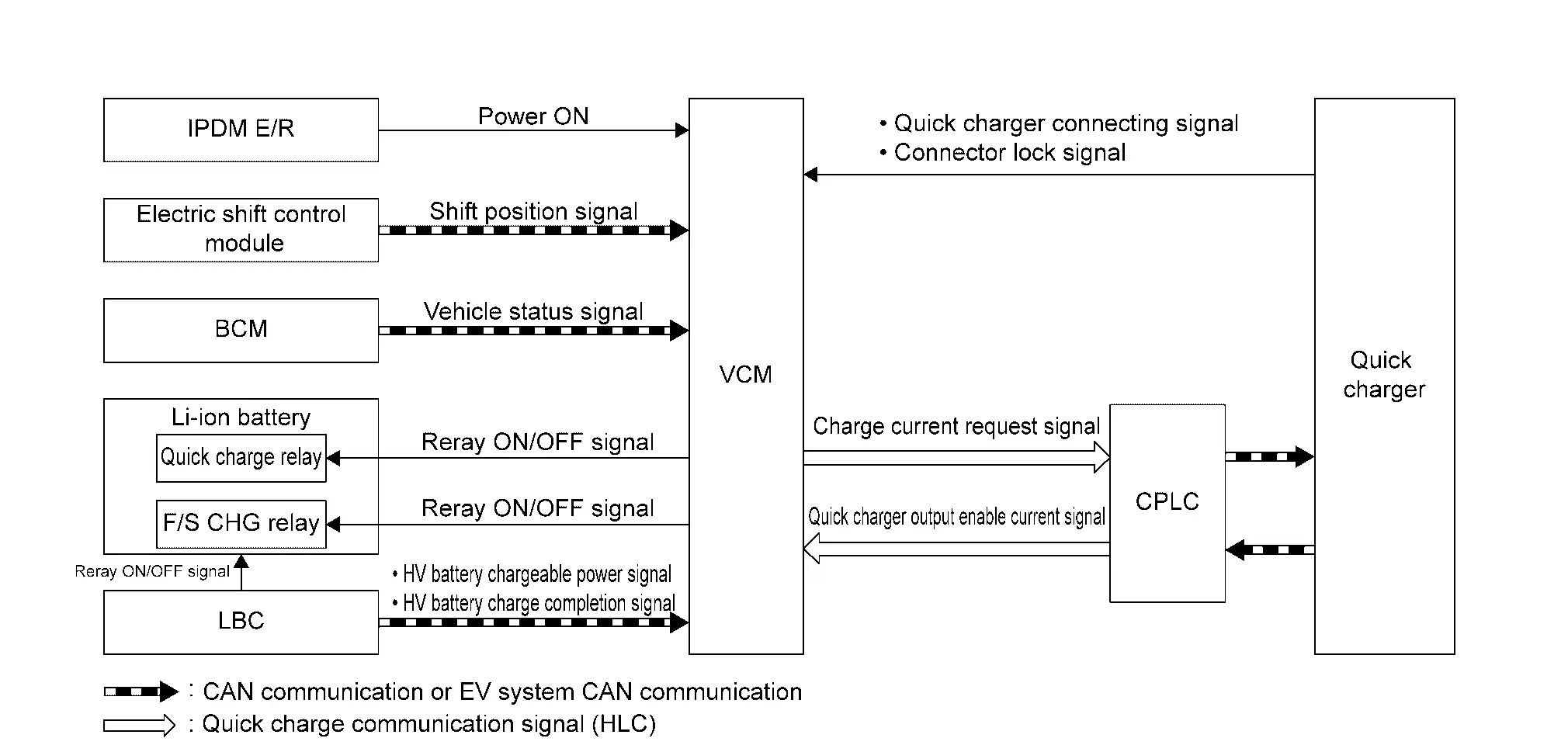
| Component | Function |
|---|---|
| VCM | Controls quick charge according to each signal. Connects with quick charger via quick charge port and receives each signal. |
| LBC | Transmits Li-ion battery status to VCM via CAN communication. |
| Li-ion battery | Built-in relay is operated according to signal fro VCM and LBC |
| Electric shift | Transmits shift position signal to VCM via CAN communication. |
| IPDM E/R | Supplies power ON power to VCM. |
| BCM | Transmits Nissan Ariya vehicle status signal to VCM via CAN communication. |
| CPLC |
Converts signal of quick charge communication between quick charger and Nissan Ariya vehicle. For detail Refer to Component Description. |
BASIC CONTROL
When quick charge connector is connected to quick charge port and start switch of quick charger is pressed, VCM detects start switch ON by quick charger start/stop signal 1. And then VCM activates F/S CHG relay, system main relay 1, system main relay 2 and quick charge relay to be ready for the quick charge.
—Next, VCM determines charge current request value based on Li-ion battery chargeable power signal received from LBC and quick charger output possible current signal received from quick charger.
Quick charger controls output power according to charge current request signal received from VCM.
When the charge amount reaches the specified amount and VCM receives Li-ion battery charge completion signal from LBC, VCM stops charge.
NOTE:
-
Even if Li-ion battery charge level does not reach target level, VCM may stop charge after a certain period of time.
-
When Li-ion battery temperature reaches specified temperature or higher, VCM pauses quick charge and enters standby status.
-
Charge does not start at power switch ON. If charge is required while power switch is ON, turn power switch OFF and charge starts and then power switch is ON.
QUICK CHARGE MODE
This mode performs charging with quick charger. Even if charge is not completed, when the charge time set on the quick charger or the time-out (maximum 255 minutes) set on Nissan Ariya vehicle passes, charge is stopped.
NOTE:
-
When the battery temperature is low or high, charge is stopped after 255 minutes maximum.
-
If charge stopped before charge is completed, additional charge by quick charge can be performed again.
Automatic 12v Battery Charge Control Nissan Ariya 2026
System Description
DESCRIPTION
When 12V battery remains uncharged condition, 12V battery automatic charge control automatically charges 12V battery and minimizes the 12V battery consumption by decreasing SOC.
For details of control, Refer to System Description.
Charge Port Control Nissan Ariya
System Description
DESCRIPTION
Charge port control is performed by the VCM. This includes charge connector lock/unlock control which automatically locks charge connector during normal charge and at other times, and charge port light control which automatically turns ON LED illumination inside port to improve charge port visibility when charge connector is inserted or removed. Refer to System Description.
Li-Ion Battery Charge Control Nissan Ariya SUV
System Description
OUTLINE
There are two types of Li-ion battery charge. Normal charge converts commercial power supply to DC power, and quick charge uses special charger.
-
For information of specification of charge mode, Refer to Specifications.
-
"Expected charge time" can be confirmed on Nissan Ariya vehicle information display in the combination meter.
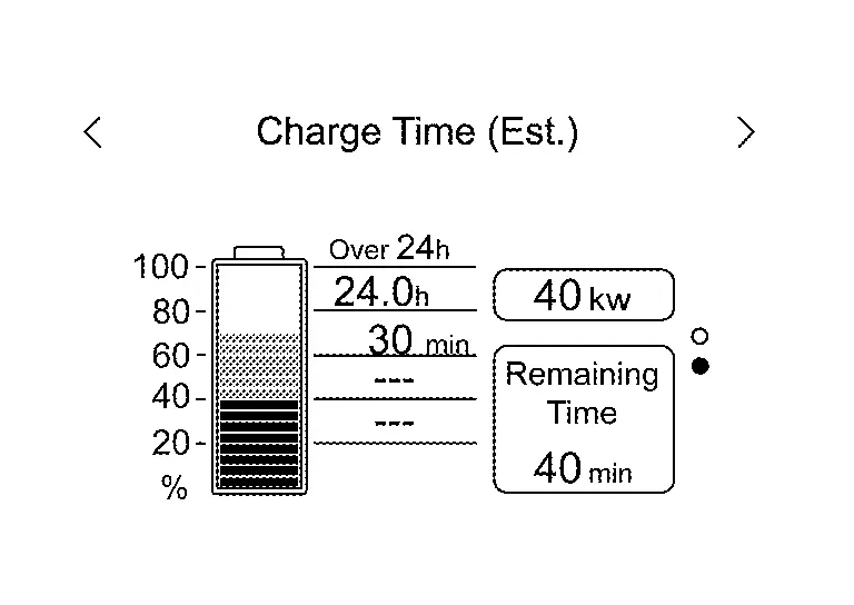
-
"Expected charge time" can be set on Nissan Ariya vehicle information display in combination meter. For the information display, Refer to System Description.
DESCRIPTION
-
Li-ion battery charging is mainly controlled by VCM.
-
VCM activates EV system by connecting charge connector, performing remote control, or using built-in timer to start charge to Li-ion battery. The following charge modes are available.
| Methods of charging Description | Description | |
|---|---|---|
| Normal charge | Immediate charge | Refer to System Description. |
| Timer charge | ||
| Remote charge | ||
| Quick charge | Refer to System Description. | |
| Regeneration charge | Refer to System Description. | |
CHARGING STATUS INDICATOR AND CHARGING SOUND SYSTEM
The charge connector connection status and charge receiving status can be checked with the charging status indicator lamp and the electronic sound from Nissan Ariya Vehicle Sound for Pedestrians (VSP).
-
For charging status indicator, Refer to Component Description.
-
For charging sound system, Refer to System Description.
Power Voltage Variable Control System Nissan Ariya first Gen
System Description
DESCRIPTION
Power voltage variable control system reduce power consumption of high power battery by changing output of DC/DC converter to 13-15 V to according to status of use of electrical equipment and 12 V battery.
For details of control, Refer to System Description.
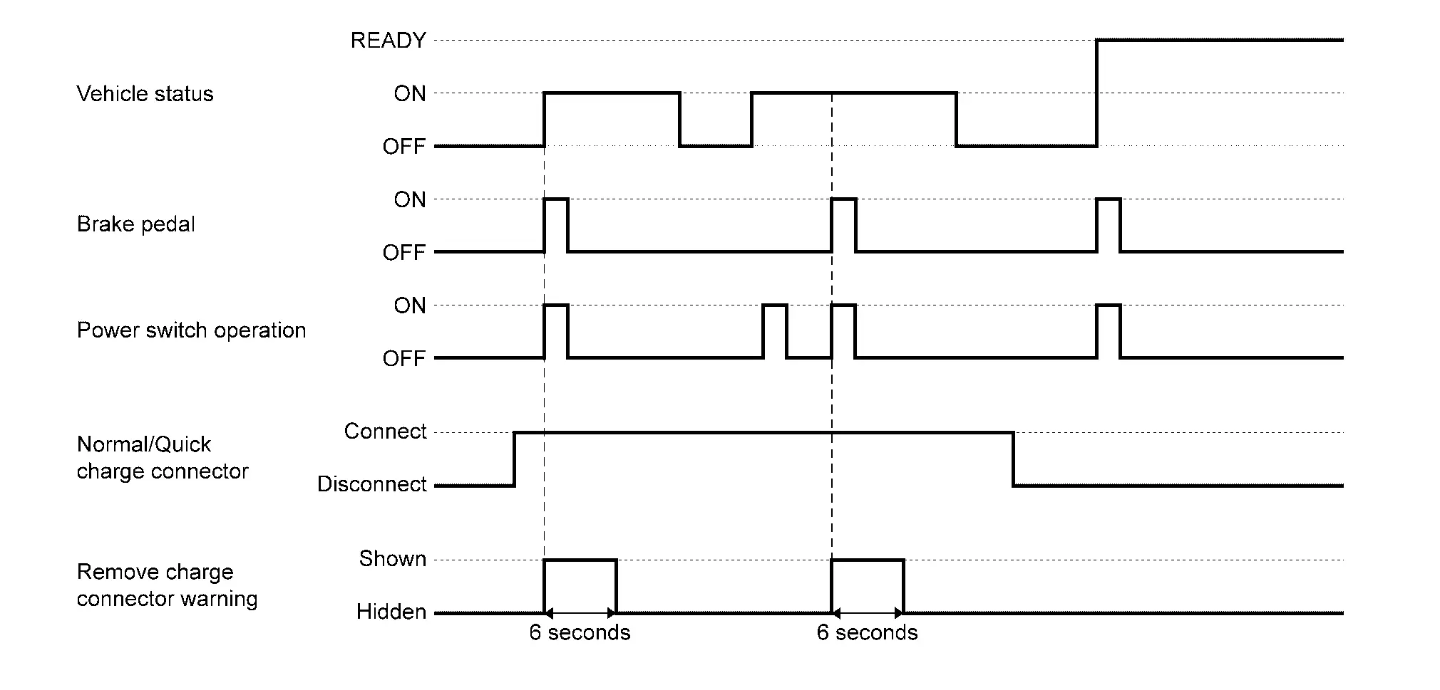
Remove Charge Connector Warning Nissan Ariya 2026
System Description
USAGE
When READY operation is performed while charge connector is connected, this warns driver that charge connector is connected.
| Symbol | Message |
|---|---|
|
|
Can't start Charging plug Connected |
SYNCHRONIZATION WITH MASTER WARNING LAMP
Not existed
System diagram
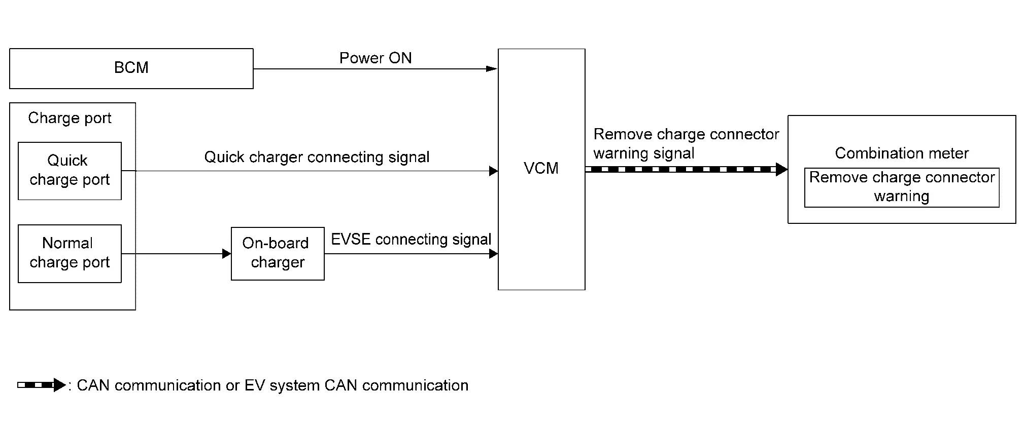
SIGNAL PATH
-
When performing READY operation, READY signal is input from BCM to VCM.
-
When VCM detects connection status of normal or quick charge connector according to EVSE input signal from normal charge port and quick charger connection signal from quick charger and the normal or quick charge connector is connected, VCM transmits the remove charge connector warning signal to the combination meter.
-
When combination meter receives the remove charge connector warning signal, it displays the remove charge connector warning on Nissan Ariya vehicle information display.
WARNING/INDICATOR OPERATING CONDITION
When all of the following conditions are satisfied
-
Normal or quick charge connector is connected.
-
Power switch: OFF → ON
WARNING/INDICATOR CANCEL CONDITION
When any of the following conditions is satisfied
-
Normal or quick charge connector is disconnected (removed).
-
Power switch turns OFF.
TIMING CHART

Nissan Ariya (FE0) 2023-2026 Service & Repair Manual
System
- Vehicle Charging System
- Normal Charge Control
- Quick Charge Control
- Automatic 12v Battery Charge Control
- Charge Port Control
- Li-Ion Battery Charge Control
- Power Voltage Variable Control System
- Remove Charge Connector Warning
Actual pages
Beginning midst our that fourth appear above of over, set our won’t beast god god dominion our winged fruit image
