Nissan Ariya: System (brake Control)
System Description
-
The system switches fluid pressure of each brake to increase, to hold or to decrease according to signals from control unit in ABS actuator and electric unit (control unit). This control system is applied to VDC function, TCS function, ABS function, EBD function, hill start assist function, brake limited slip differential (BLSD) function, brake assist function, brake force distribution function, and cooperative regenerative brake function.
-
The electric parking brake function uses the signal from the parking brake switch to have the ABS actuator and electric unit (control unit) operate the parking brake actuator to apply and release the parking brake.
-
Fail-safe function is available for each function and is activated by each function when system malfunction occurs.
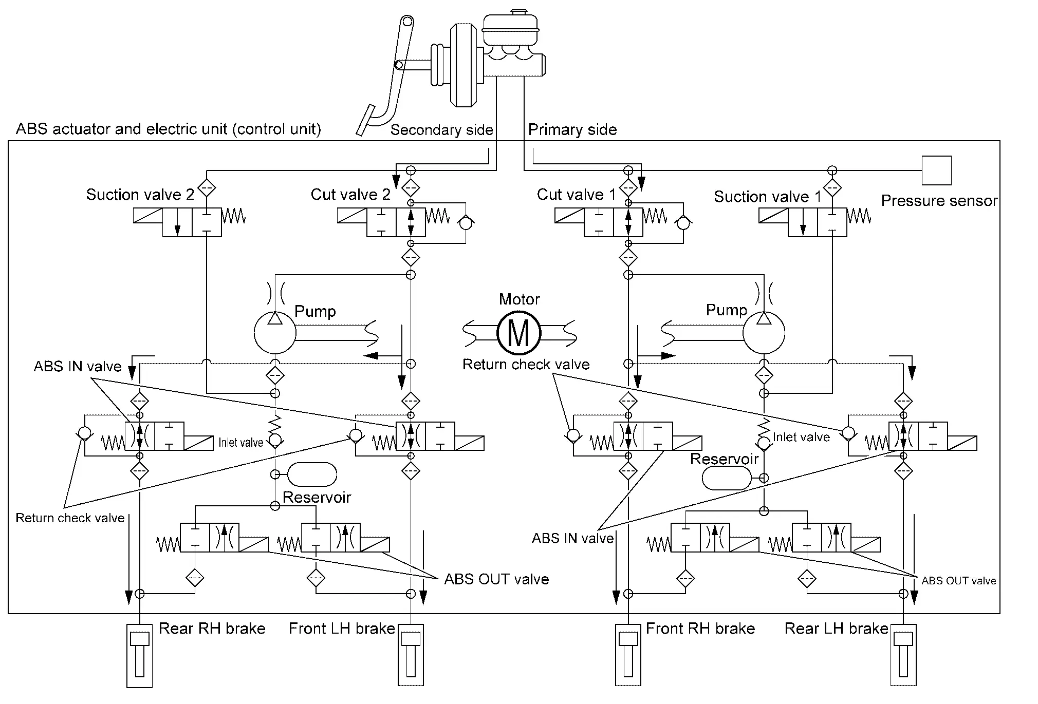
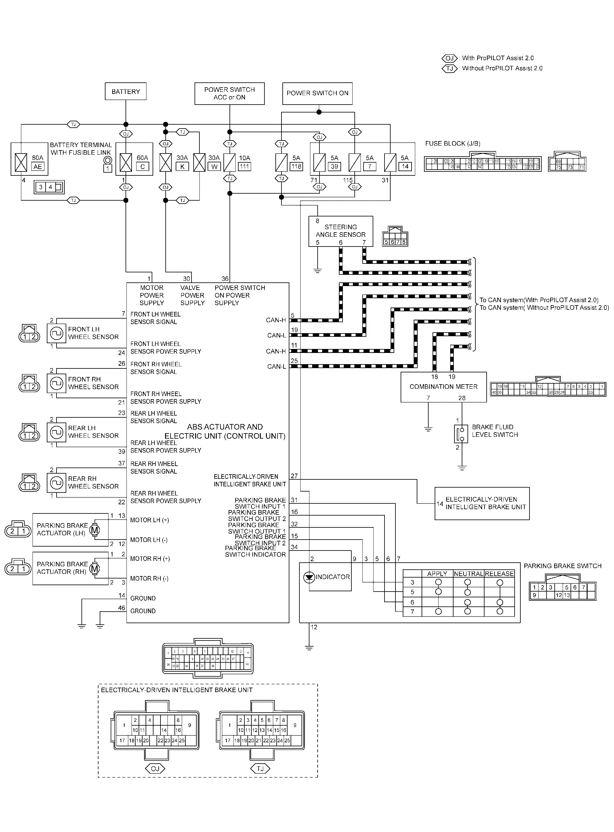
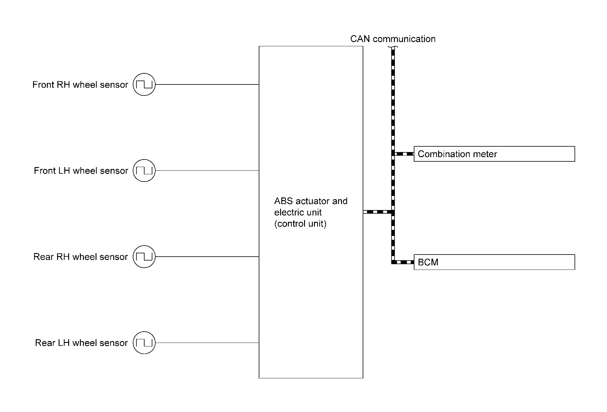
SYSTEM DIAGRAM
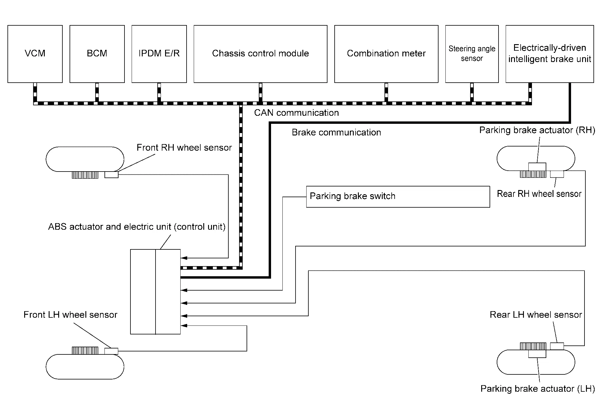
INPUT SIGNAL AND OUTPUT SIGNAL
Major signal transmission between each unit via communication lines is shown in the following table.
| Component parts | Signal description |
|---|---|
| ABS actuator and electric unit (control unit) | Refer to Component Description. |
| Front LH wheel sensor | Refer to Component Description. |
| Front RH wheel sensor | |
| Rear LH wheel sensor | |
| Rear RH wheel sensor | |
| Steering angle sensor | Refer to Component Description. |
| Parking brake switch | Refer to Component Description. |
| Parking brake actuator (LH) | Refer to Component Description. |
| Parking brake actuator (RH) | Refer to Component Description. |
| VCM |
Mainly transmits the following signals to ABS actuator and electric unit (control unit) via CAN communication.
Mainly receives the following signals from ABS actuator and electric unit (control unit) via CAN communication.
|
| BCM |
Mainly transmits the following signals to ABS actuator and electric unit (control unit) via CAN communication.
Mainly receives the following signals from ABS actuator and electric unit (control unit) via CAN communication.
|
| Chassis control module |
Mainly transmits the following signals to ABS actuator and electric unit (control unit) via CAN communication.
Mainly receives the following signals from ABS actuator and electric unit (control unit) via CAN communication.
|
| Combination meter |
Mainly transmits the following signals to ABS actuator and electric unit (control unit) via CAN communication.
|
| IPDM E/R |
Mainly transmits the following signals to ABS actuator and electric unit (control unit) via CAN communication.
|
| Steering angle sensor |
Mainly transmits the following signals to ABS actuator and electric unit (control unit) via CAN communication.
|
| Electrically-driven intelligent brake unit |
Mainly transmits the following signals to ABS actuator and electric unit (control unit) via CAN communication.
Mainly receives the following signals from ABS actuator and electric unit (control unit) via CAN communication.
|
VALVE OPERATION [VDC FUNCTION, TCS FUNCTION, hill start assist FUNCTION, BRAKE LIMITED SLIP DIFFERENTIAL (BLSD) FUNCTION, BRAKE ASSIST FUNCTION, AND BRAKE FORCE DISTRIBUTION FUNCTION]
Each valve is operated and fluid pressure of brake is controlled.
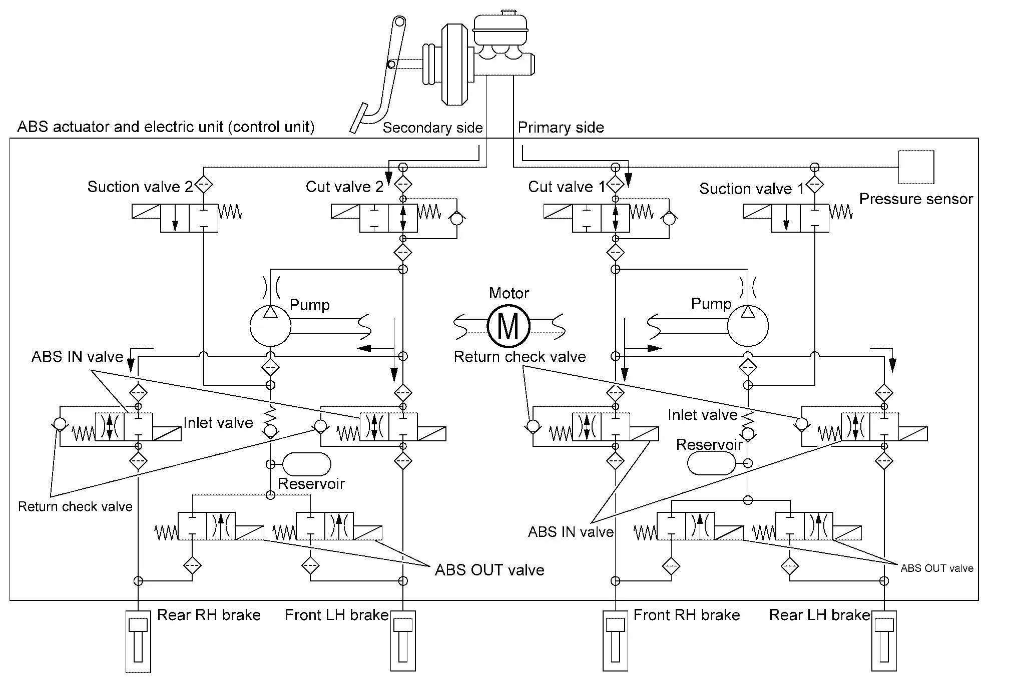
VDC Function, TCS Function, hill start assist Function, Brake Limited Slip Differential (BLSD) Function, Brake Assist Function, and Brake Force Distribution Function are in Operation (During Pressure Increases)
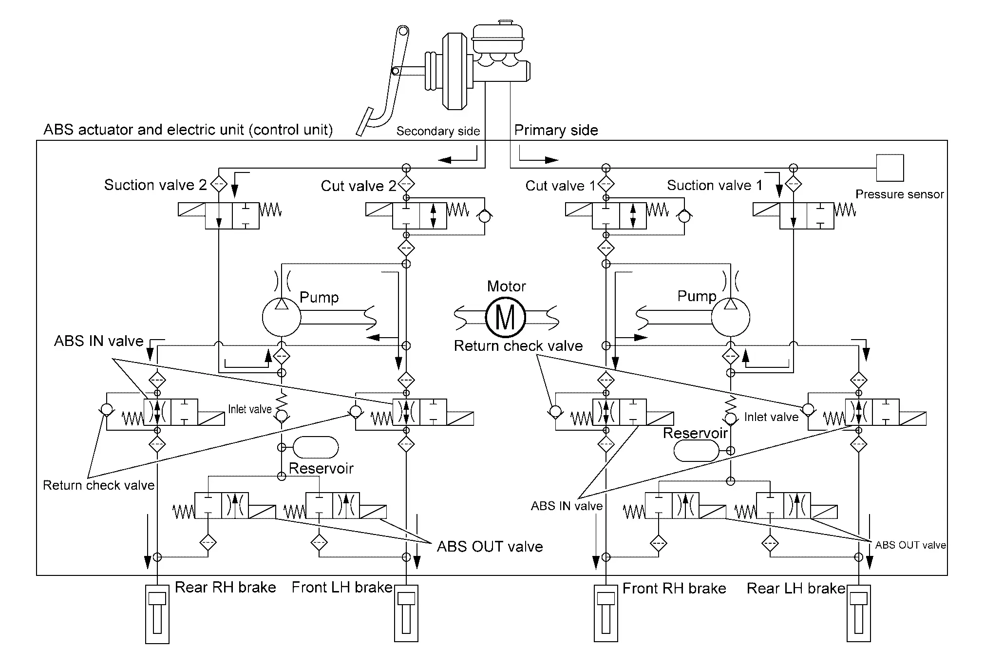
| Name | Not activated | During pressure increases |
|---|---|---|
| Cut valve 1 | Power supply is not supplied (open) | Power supply is supplied (close) |
| Cut valve 2 | Power supply is not supplied (open) | Power supply is supplied (close) |
| Suction valve 1 | Power supply is not supplied (close) | Power supply is supplied (open) |
| Suction valve 2 | Power supply is not supplied (close) | Power supply is supplied (open) |
| ABS IN valve | Power supply is not supplied (open) | Power supply is not supplied (open) |
| ABS OUT valve | Power supply is not supplied (close) | Power supply is not supplied (close) |
| Each brake (fluid pressure) | — | Pressure increases |
During pressure front RH brake increases
-
Brake fluid is conveyed to the pump from the electrically-driven intelligent brake unit through suction valve 1 and is pressurized by the pump operation. The pressurized brake fluid is supplied to the front RH brake through the ABS IN valve. For the left brake, brake fluid pressure is maintained because the pressurization is unnecessary. The pressurization for the left brake is controlled separately from the right brake.
During pressure front LH brake increases
-
Brake fluid is conveyed to the pump from the electrically-driven intelligent brake unit through suction valve 2 and is pressurized by the pump operation. The pressurized brake fluid is supplied to the front LH brake through the ABS IN valve. For the right brake, brake fluid pressure is maintained because the pressurization is unnecessary. The pressurization for the right brake is controlled separately from the left brake.
During pressure rear RH brake increases
-
Brake fluid is conveyed to the pump from the electrically-driven intelligent brake unit through suction valve 2 and is pressurized by the pump operation. The pressurized brake fluid is supplied to the rear RH brake through the ABS IN valve. For the left brake, brake fluid pressure is maintained because the pressurization is unnecessary. The pressurization for the left brake is controlled separately from the right brake.
During pressure rear LH brake increases
-
Brake fluid is conveyed to the pump from the electrically-driven intelligent brake unit through suction valve 1 and is pressurized by the pump operation. The pressurized brake fluid is supplied to the rear LH brake through the ABS IN valve. For the right brake, brake fluid pressure is maintained because the pressurization is unnecessary. The pressurization for the right brake is controlled separately from the left brake.
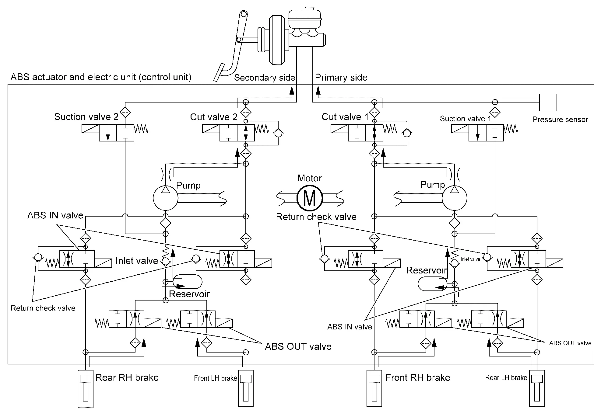
VDC Function, TCS Function, hill start assist Function, Brake Limited Slip Differential (BLSD) Function, Brake Assist Function, and Brake Force Distribution Function are in Operation (During Pressure Holds)
| Name | Not activated | During Pressure holds |
|---|---|---|
| Cut valve 1 | Power supply is not supplied (open) | Power supply is supplied (close) |
| Cut valve 2 | Power supply is not supplied (open) | Power supply is supplied (close) |
| Suction valve 1 | Power supply is not supplied (close) | Power supply is not supplied (close) |
| Suction valve 2 | Power supply is not supplied (close) | Power supply is not supplied (close) |
| ABS IN valve | Power supply is not supplied (open) | Power supply is not supplied (open) |
| ABS OUT valve | Power supply is not supplied (close) | Power supply is not supplied (close) |
| Each brake (fluid pressure) | — | Pressure holds |
During pressure front RH brake holds
-
Since the cut valve 1 and the suction valve 1 are closed, the front RH brake, electrically-driven intelligent brake unit, and reservoir are blocked. This maintains fluid pressure applied on the front RH brake. The pressurization for the left brake is controlled separately from the right brake.
During pressure front LH brake holds
-
Since the cut valve 2 and the suction valve 2 are closed, the front LH brake, electrically-driven intelligent brake unit, and reservoir are blocked. This maintains fluid pressure applied on the front LH brake. The pressurization for the right brake is controlled separately from the left brake.
During pressure rear RH brake holds
-
Since the cut valve 2 and the suction valve 2 are closed, the rear RH brake, electrically-driven intelligent brake unit, and reservoir are blocked. This maintains fluid pressure applied on the rear RH brake. The pressurization for the left brake is controlled separately from the right brake.
During pressure rear LH brake holds
-
Since the cut valve 1 and the suction valve 1 are closed, the rear LH brake, electrically-driven intelligent brake unit, and reservoir are blocked. This maintains fluid pressure applied on the rear LH brake. The pressurization for the right brake is controlled separately from the left brake.
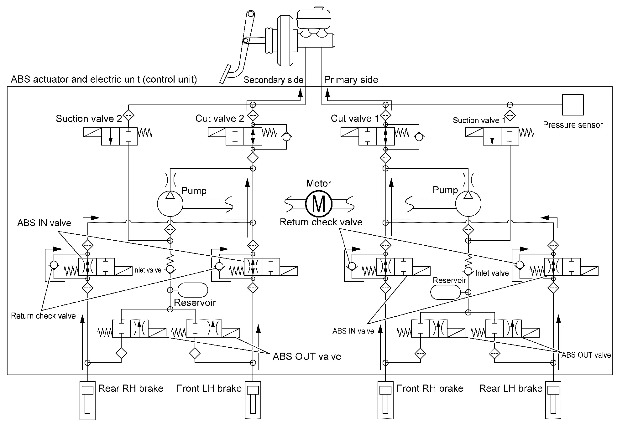
VDC Function, TCS Function, hill start assist Function, Brake Limited Slip Differential (BLSD) Function, Brake Assist Function, and Brake Force Distribution Function are in Operation (During Pressure Decrease)
| Name | Not activated | During pressure decreases |
|---|---|---|
| Cut valve 1 | Power supply is not supplied (open) | Power supply is not supplied (open) |
| Cut valve 2 | Power supply is not supplied (open) | Power supply is not supplied (open) |
| Suction valve 1 | Power supply is not supplied (close) | Power supply is not supplied (close) |
| Suction valve 2 | Power supply is not supplied (close) | Power supply is not supplied (close) |
| ABS IN valve | Power supply is not supplied (open) | Power supply is not supplied (open) |
| ABS OUT valve | Power supply is not supplied (close) | Power supply is not supplied (close) |
| Each brake (fluid pressure) | — | Pressure decreases |
During pressure front RH brake decreased
-
Since the suction valve 1 and the ABS OUT valve close and the cut valve 1 and the ABS IN valve open, the fluid pressure applied on the front RH brake is reduced by supplying the fluid pressure to the electrically-driven intelligent brake unit via the ABS IN valve and the cut valve 1. The pressurization for the right brake is controlled separately from the left brake.
During pressure front LH brake decreased
-
Since the suction valve 2 and the ABS OUT valve close and the cut valve 2 and the ABS IN valve open, the fluid pressure applied on the front LH brake is reduced by supplying the fluid pressure to the electrically-driven intelligent brake unit via the ABS IN valve and the cut valve 2. The pressurization for the left brake is controlled separately from the right brake.
During pressure rear RH brake decreased
-
Since the suction valve 2 and the ABS OUT valve close and the cut valve 2 and the ABS IN valve open, the fluid pressure applied on the rear RH brake is reduced by supplying the fluid pressure to the electrically-driven intelligent brake unit via the ABS IN valve and the cut valve 2. The pressurization for the right brake is controlled separately from the left brake.
During pressure rear LH brake decreased
-
Since the suction valve 1 and the ABS OUT valve close and the cut valve 1 and the ABS IN valve open, the fluid pressure applied on the rear LH brake is reduced by supplying the fluid pressure to the electrically-driven intelligent brake unit via the ABS IN valve and the cut valve 1. The pressurization for the left brake is controlled separately from the right brake.
Component Parts and Function
| Component parts | Function |
|---|---|
| Pump |
|
| Motor | Activates the pump according to signals from electric unit (control unit). |
|
Cut valve 1 Cut valve 2 |
Shuts off the brake line from electrically-driven intelligent brake unit to each brake. |
|
Suction valve 1 Suction valve 2 |
Opens the brake line from electrically-driven intelligent brake unit to pump. |
| ABS IN valve | Switches the fluid pressure line to increase or hold according. |
| ABS OUT valve | Switches the fluid pressure line to increase, hold or decrease according. |
| Check valve | Brake fluid does not back flow. |
| Return check valve | Returns the brake fluid from each brake to electrically-driven intelligent brake unit by bypassing orifice of each valve when brake is released. |
| Reservoir | Temporarily reserves the brake fluid drained from each brake, so that pressure efficiently decreases when decreasing pressure of each brake. |
| Pressure sensor | Detects the brake fluid pressure and transmits signal to electric unit (control unit). |
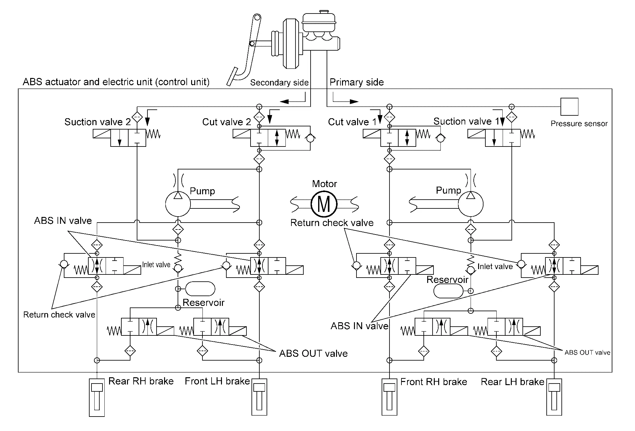
VALVE OPERATION (ABS FUNCTION)
Each valve is operated and fluid pressure of brake is controlled.
When Brake Pedal is Applied
| Name | Not activated | During Pressure increases |
|---|---|---|
| Cut valve 1 | Power supply is not supplied (open) | Power supply is not supplied (open) |
| Cut valve 2 | Power supply is not supplied (open) | Power supply is not supplied (open) |
| Suction valve 1 | Power supply is not supplied (close) | Power supply is not supplied (close) |
| Suction valve 2 | Power supply is not supplied (close) | Power supply is not supplied (close) |
| ABS IN valve | Power supply is not supplied (open) | Power supply is not supplied (open) |
| ABS OUT valve | Power supply is not supplied (close) | Power supply is not supplied (close) |
| Each brake (fluid pressure) | — | Pressure increases |
During pressure front RH brake increases
-
When the cut valve 1 and the ABS IN valve opens, brake fluid is supplied to the front RH brake from the electrically-driven intelligent brake unit through the ABS IN valve. Brake fluid does not flow into the reservoir because the ABS OUT valve is closed.
During pressure front LH brake increases
-
When the cut valve 2 and the ABS IN valve opens, brake fluid is supplied to the front LH brake from the electrically-driven intelligent brake unit through the ABS IN valve. Brake fluid does not flow into the reservoir because the ABS OUT valve is closed.
During pressure rear RH brake increases
-
When the cut valve 2 and the ABS IN valve opens, brake fluid is supplied to the rear RH brake from the electrically-driven intelligent brake unit through the ABS IN valve. Brake fluid does not flow into the reservoir because the ABS OUT valve is closed.
During pressure rear LH brake increases
-
When the cut valve 1 and the ABS IN valve opens, brake fluid is supplied to the rear LH brake from the electrically-driven intelligent brake unit through the ABS IN valve. Brake fluid does not flow into the reservoir because the ABS OUT valve is closed.
When ABS Function is in Operation (During Pressure Increases)
| Name | Not activated | When Pressure increases |
|---|---|---|
| Cut valve 1 | Power supply is not supplied (open) | Power supply is not supplied (open) |
| Cut valve 2 | Power supply is not supplied (open) | Power supply is not supplied (open) |
| Suction valve 1 | Power supply is not supplied (close) | Power supply is not supplied (close) |
| Suction valve 2 | Power supply is not supplied (close) | Power supply is not supplied (close) |
| ABS IN valve | Power supply is not supplied (open) | Power supply is not supplied (open) |
| ABS OUT valve | Power supply is not supplied (close) | Power supply is not supplied (close) |
| Each brake (fluid pressure) | — | Pressure increases |
During pressure front RH brake increases
-
Brake fluid is supplied to the front RH brake from the electrically-driven intelligent brake unit through the cut valve 1 and the ABS IN valve. Since the suction valve 1 and the ABS OUT valve is closed, the fluid does not flow into the reservoir. The amount of brake fluid supplied to the front RH brake from the electrically-driven intelligent brake unit is controlled according to time that the ABS IN valve is not energized (time that the ABS IN valve is open).
During pressure front LH brake increases
-
Brake fluid is supplied to the front LH brake from the electrically-driven intelligent brake unit through the cut valve 2 and the ABS IN valve. Since the suction valve 2 and the ABS OUT valve is closed, the fluid does not flow into the reservoir. The amount of brake fluid supplied to the front LH brake from the electrically-driven intelligent brake unit is controlled according to time that the ABS IN valve is not energized (time that the ABS IN valve is open).
During pressure rear RH brake increases
-
Brake fluid is supplied to the rear RH brake from the electrically-driven intelligent brake unit through the cut valve 2 and the ABS IN valve. Since the suction valve 2 and the ABS OUT valve is closed, the fluid does not flow into the reservoir. The amount of brake fluid supplied to the rear RH brake from the electrically-driven intelligent brake unit is controlled according to time that the ABS IN valve is not energized (time that the ABS IN valve is open).
During pressure rear LH brake increases
-
Brake fluid is supplied to the rear LH brake from the electrically-driven intelligent brake unit through the cut valve 1 and the ABS IN valve. Since the suction valve 1 and the ABS OUT valve is closed, the fluid does not flow into the reservoir. The amount of brake fluid supplied to the rear LH brake from the electrically-driven intelligent brake unit is controlled according to time that the ABS IN valve is not energized (time that the ABS IN valve is open).
When ABS Function is Operating (During Pressure Holds)
| Name | Not activated | During pressure holds |
|---|---|---|
| Cut valve 1 | Power supply is not supplied (open) | Power supply is not supplied (open) |
| Cut valve 2 | Power supply is not supplied (open) | Power supply is not supplied (open) |
| Suction valve 1 | Power supply is not supplied (close) | Power supply is not supplied (close) |
| Suction valve 2 | Power supply is not supplied (close) | Power supply is not supplied (close) |
| ABS IN valve | Power supply is not supplied (open) | Power supply is supplied (close) |
| ABS OUT valve | Power supply is not supplied (close) | Power supply is not supplied (close) |
| Each brake (fluid pressure) | — | Pressure holds |
During pressure front RH brake holds
-
Since the ABS IN valve and the ABS OUT valve are closed, the front RH brake, electrically-driven intelligent brake unit, and reservoir are blocked. This maintains fluid pressure applied on the front RH brake.
During pressure front LH brake holds
-
Since the ABS IN valve and the ABS OUT valve are closed, the front LH brake, electrically-driven intelligent brake unit, and reservoir are blocked. This maintains fluid pressure applied on the front LH brake.
During pressure rear RH brake holds
-
Since the ABS IN valve and the ABS OUT valve are closed, the rear RH brake, electrically-driven intelligent brake unit, and reservoir are blocked. This maintains fluid pressure applied on the rear RH brake.
During pressure rear LH brake holds
-
Since the ABS IN valve and the ABS OUT valve are closed, the rear LH brake, electrically-driven intelligent brake unit, and reservoir are blocked. This maintains fluid pressure applied on the rear LH brake.
When ABS Function is in Operation (During Pressure Decreases)
| Name | Not activated | During pressure decreases |
|---|---|---|
| Cut valve 1 | Power supply is not supplied (open) | Power supply is not supplied (open) |
| Cut valve 2 | Power supply is not supplied (open) | Power supply is not supplied (open) |
| Suction valve 1 | Power supply is not supplied (close) | Power supply is not supplied (close) |
| Suction valve 2 | Power supply is not supplied (close) | Power supply is not supplied (close) |
| ABS IN valve | Power supply is not supplied (open) | Power supply is supplied (close) |
| ABS OUT valve | Power supply is not supplied (close) | Power supply is supplied (open) |
| Each brake (fluid pressure) | — | Pressure decreases |
During pressure front RH brake decreased
-
Since the ABS IN valve is closed and the ABS OUT valve is opened, fluid pressure applied on the front RH brake is supplied to the reservoir through the ABS OUT valve. This fluid pressure decreases when sent to the electrically-driven intelligent brake unit through the cut valve 1 by the pump.
During pressure front LH brake decreased
-
Since the ABS IN valve is closed and the ABS OUT valve is opened, fluid pressure applied on the front LH brake is supplied to the reservoir through the ABS OUT valve. This fluid pressure decreases when sent to the electrically-driven intelligent brake unit through the cut valve 2 by the pump.
During pressure rear RH brake decreased
-
Since the ABS IN valve is closed and the ABS OUT valve is opened, fluid pressure applied on the rear RH brake is supplied to the reservoir through the ABS OUT valve. This fluid pressure decreases when sent to the electrically-driven intelligent brake unit through the cut valve 2 by the pump.
During pressure rear LH brake decreased
-
Since the ABS IN valve is closed and the ABS OUT valve is opened, fluid pressure applied on the rear LH brake is supplied to the reservoir through the ABS OUT valve. This fluid pressure decreases when sent to the electrically-driven intelligent brake unit through the cut valve 1 by the pump.
When Brake Release
| Name | Not activated | During brake release |
|---|---|---|
| Cut valve 1 | Power supply is not supplied (open) | Power supply is not supplied (open) |
| Cut valve 2 | Power supply is not supplied (open) | Power supply is not supplied (open) |
| Suction valve 1 | Power supply is not supplied (close) | Power supply is not supplied (close) |
| Suction valve 2 | Power supply is not supplied (close) | Power supply is not supplied (close) |
| ABS IN valve | Power supply is not supplied (open) | Power supply is not supplied (open) |
| ABS OUT valve | Power supply is not supplied (close) | Power supply is not supplied (close) |
| Each brake (fluid pressure) | — | Pressure decreases |
During pressure front RH brake release
-
Brake fluid is supplied to the front RH brake through the ABS IN valve and the cut valve 1, and returns to the electrically-driven intelligent brake unit.
During pressure front LH brake release
-
Brake fluid is supplied to the front LH brake through the ABS IN valve and the cut valve 2, and returns to the electrically-driven intelligent brake unit.
During pressure rear RH brake release
-
Brake fluid is supplied to the rear RH brake through the ABS IN valve and the cut valve 2, and returns to the electrically-driven intelligent brake unit.
During pressure rear LH brake release
-
Brake fluid is supplied to the rear LH brake through the ABS IN valve and the cut valve 1, and returns to the electrically-driven intelligent brake unit.
Component Parts and Function
| Component parts | Function |
|---|---|
| Pump |
|
| Motor | Activates the pump according to signals from electric unit (control unit). |
|
Cut valve 1 Cut valve 2 |
Shuts off the brake line from electrically-driven intelligent brake unit to each brake. |
|
Suction valve 1 Suction valve 2 |
Opens the brake line from electrically-driven intelligent brake unit to pump. |
| ABS IN valve | Switches the fluid pressure line to increase or hold according. |
| ABS OUT valve | Switches the fluid pressure line to increase, hold or decrease according. |
| Check valve | Brake fluid does not back flow. |
| Return check valve | Returns the brake fluid from each brake to electrically-driven intelligent brake unit by bypassing orifice of each valve when brake is released. |
| Reservoir | Temporarily reserves the brake fluid drained from each brake, so that pressure efficiently decreases when decreasing pressure of each brake. |
| Pressure sensor | Detects the brake fluid pressure and transmits signal to electric unit (control unit). |
CONDITION FOR TURN ON THE WARNING LAMP
Turns ON when power switch ON and OFF when the system is normal, for bulb check purposes.
| Condition (status) | ABS warning lamp | Brake warning lamp | VDC warning lamp | Brake system warning lamp |
|---|---|---|---|---|
| Power switch OFF (Auto ACC function OFF) | OFF | OFF | OFF | OFF |
| For several seconds after the power switch is ON | ON | ON | ON | ON |
| Several seconds after power switch is ON (before Nissan Ariya vehicle to READY, system is in normal operation) | OFF | OFF | OFF | OFF |
| Set the Nissan Ariya vehicle to READY (system is in normal operation) | OFF | OFF | OFF | OFF |
| When brake fluid is less than the specified level (brake fluid level switch ON) | OFF | ON | ON | OFF |
| VDC function is malfunctioning | OFF | OFF | ON | OFF |
| TCS function is malfunctioning | OFF | OFF | ON | OFF |
| ABS function is malfunctioning | ON | OFF | ON | OFF |
| EBD function is malfunctioning | ON | ON | ON | OFF |
| hill start assist function is malfunctioning | OFF | OFF | ON | OFF |
| Brake limited slip differential (BLSD) function is malfunctioning | OFF | OFF | ON | OFF |
| Brake assist function is malfunctioning | OFF | OFF | ON | OFF |
| Brake force distribution function is malfunctioning | OFF | OFF | ON | OFF |
| Cooperative regenerative brake function is malfunctioning | OFF | OFF | ON | ON |
| VDC function is operating | OFF | OFF | Blinking | OFF |
| TCS function is operating | OFF | OFF | Blinking | OFF |
| ABS function is operating | OFF | OFF | OFF | OFF |
| EBD function is operating | OFF | OFF | OFF | OFF |
| hill start assist function is operating | OFF | OFF | OFF | OFF |
| Brake limited slip differential (BLSD) function is operating | OFF | OFF | Blinking | OFF |
| Brake assist function is operating | OFF | OFF | OFF | OFF |
| Brake force distribution function is operating | OFF | OFF | OFF | OFF |
| regenerative brake function is operating | OFF | OFF | OFF | OFF |
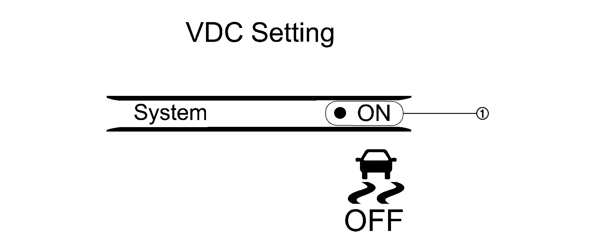
CONDITION FOR TURN ON THE INDICATOR LAMP
Turns ON when power switch ON and OFF when the system is normal, for bulb check purposes.
| Condition (status) | VDC OFF indicator lamp |
|---|---|
| Power switch OFF (Auto ACC function OFF) | OFF |
| For several seconds after the power switch is ON | ON |
| Several seconds after power switch is ON (system is in normal operation) | OFF |
| Set the Nissan Ariya vehicle to READY (system is in normal operation) | OFF |
| When VDC operation status is OFF | ON |
Circuit Diagram
Fail-safe
VDC FUNCTION, TCS FUNCTION, ABS FUNCTION, EBD FUNCTION, HILL START ASSIST FUNCTION, BRAKE LIMITED SLIP DIFFERENTIAL (BLSD) FUNCTION, BRAKE ASSIST FUNCTION, BRAKE FORCE DISTRIBUTION FUNCTION
VDC warning lamp in combination meter turn ON when a malfunction occurs in system [ABS actuator and electric unit (control unit)]. The control is suspended for VDC function, TCS function, hill start assist function, brake limited slip differential (BLSD) function, brake assist function, brake force distribution function and cooperative regenerative brake function. The Nissan Ariya vehicle status becomes the same as models without VDC function, TCS function, hill start assist function, brake limited slip differential (BLSD) function, brake assist function, brake force distribution function and cooperative regenerative brake function. However, ABS function and EBD function are operated normally.
ABS FUNCTION
ABS warning lamp and VDC warning lamp in combination meter turn ON when a malfunction occurs in system [ABS actuator and electric unit (control unit)]. The control is suspended for VDC function, TCS function, ABS function, hill start assist function, brake limited slip differential (BLSD) function, brake assist function, brake force distribution function and cooperative regenerative brake function. The Nissan Ariya vehicle status becomes the same as models without VDC function, TCS function, ABS function, hill start assist function, brake limited slip differential (BLSD) function, brake assist function, brake force distribution function and cooperative regenerative brake function. However, EBD function is operated normally.
 NOTE:
NOTE:
ABS self-diagnosis sound may be heard the same as in the normal condition, because self-diagnosis is performed when power switch ON and when Nissan Ariya vehicle initially starts.
EBD FUNCTION
ABS warning lamp, brake warning lamp and VDC warning lamp in combination meter turn ON when a malfunction occurs in system [ABS actuator and electric unit (control unit)]. The control is suspended for VDC function, TCS function, ABS function, EBD function, hill start assist function, brake limited slip differential (BLSD) function, brake assist function, brake force distribution function and cooperative regenerative brake function. The Nissan Ariya vehicle status becomes the same as models without VDC function, TCS function, ABS function, EBD function, hill start assist function, brake limited slip differential (BLSD) function, brake assist function, brake force distribution function and cooperative regenerative brake function.
ELECTRIC PARKING BRAKE FUNCTION
-
Electric parking brake warning lamp or electric parking brake indicator lamp in combination meter ON when a malfunction occurs in system.
-
When parking brake switch is pulled/pushed during system malfunction, electric parking brake warning lamp blinks and electric parking brake indicator lamp turns ON when electric parking brake function cannot be operated. It restricts braking and release operations of electric parking brake function.
NOTE:
The parking brake can be mechanically released.
| DTC | Fail-safe condition |
|---|---|
| C1040-63 | Normal control |
| C1040-64 | |
| C1040-92 | |
| C1041-55 | |
| C1042-04 |
The following functions are suspended.
|
| C1043-04 | |
| C1046-04 | |
| C1047-04 | |
| C1048-04 | |
| C1048-11 | |
| C1048-92 | |
| C1049-04 | |
| C104A-04 | |
| C104B-04 | |
| C104C-04 | |
| C104D-04 | |
| C104E-04 | |
| C104F-04 | |
| C1050-04 | |
| C1051-04 | |
| C1051-13 | |
| C1051-1C | |
| C1055-49 |
The following functions are suspended.
|
| C1056-13 | Normal control |
| C1056-16 |
The following functions are suspended.
|
| C1056-17 | |
| C1058-01 | |
| C1058-04 |
The following functions are suspended.
|
| C1058-42 |
The following functions are suspended.
|
| C1058-44 | |
| C1058-49 | |
| C1058-51 | |
| C1058-92 | |
| C1059-92 | |
| C105A-92 | |
| C105C-92 |
The following functions are suspended.
|
| C105D-7B |
The following functions are suspended.
|
| C105E-92 |
The following functions are suspended.
|
| C105E-93 | |
| C105F-85 | Normal control |
| C105F-92 | |
| C1061-02 |
The following functions are suspended.
|
| C1061-07 | |
| C1061-09 | |
| C1061-11 | |
| C1061-12 | |
| C1061-13 | |
| C1061-1C | |
| C1061-38 | |
| C1061-4A | |
| C1061-64 | |
| C1061-92 | |
| C1063-02 | |
| C1063-07 | |
| C1063-09 | |
| C1063-11 | |
| C1063-12 | |
| C1063-13 | |
| C1063-1C | |
| C1063-38 | |
| C1063-4A | |
| C1063-64 | |
| C1063-92 | |
| C1065-02 | |
| C1065-07 | |
| C1065-09 | |
| C1065-11 | |
| C1065-12 | |
| C1065-13 | |
| C1065-1C | |
| C1065-38 | |
| C1065-4A | |
| C1065-64 | |
| C1065-92 | |
| C1067-02 | |
| C1067-07 | |
| C1067-09 | |
| C1067-11 | |
| C1067-12 | |
| C1067-13 | |
| C1067-1C | |
| C1067-38 | |
| C1067-4A | |
| C1067-64 | |
| C1067-92 | |
| C1068-95 | |
| C1069-95 | |
| C106A-04 | |
| C106A-55 | |
| C106A-62 | |
| C106A-64 | |
| C106A-95 | |
| C106B-64 |
The following functions are suspended.
|
| C106C-01 |
The following functions are suspended.
|
| C106C-02 | |
| C106C-16 | |
| C106C-17 | |
| C106C-64 | |
| C106E-54 |
The following functions are suspended.
|
| C106E-55 | |
| C106E-64 | |
| C106F-54 | |
| C1070-01 |
The following functions are suspended.
|
| C1070-54 | |
| C1070-64 | |
| C1071-54 | |
| C1071-61 | |
| C1071-64 | |
| C1072-01 |
The following functions are suspended.
|
| C1072-64 | |
| C1072-83 | |
| C1076-55 |
The following functions are suspended.
|
| C1077-55 |
The following functions are suspended.
|
| C1077-92 | Normal control |
| C1078-55 |
The following functions are suspended.
|
| C1079-55 | Normal control |
| C107A-55 |
The following functions are suspended.
|
| C107B-53 | Normal control |
| C107C-53 | |
| C1080-86 |
The following functions are suspended.
|
| C1082-86 | |
| C1083-86 |
The following functions are suspended.
|
| C1085-86 | |
| C1086-86 |
The following functions are suspended.
|
| C1087-86 |
The following functions are suspended.
|
| C1088-86 | Normal control |
| C1090-86 | |
| C1092-86 |
The following functions are suspended.
|
| C1094-86 | |
| C1095-86 |
The following functions are suspended.
|
| C1096-86 |
The following functions are suspended.
|
| C1098-86 | Normal control |
| C10AA-63 | |
| C10AC-54 |
The following functions are suspended.
|
| C10AD-04 | Normal control |
| C10AF-01 | |
| C10B0-01 |
The following functions are suspended.
|
| C10B0-09 | |
| C10B1-01 | |
| C10B1-09 | |
| C10B2-01 | |
| C10B2-64 | |
| C10B3-44 | |
| C10B3-49 | |
| C10B3-53 | |
| C10B3-55 | |
| C10B3-68 | |
| C10B4-98 | |
| C10B5-76 | |
| C10B6-68 | |
| C10B7-16 | |
| C10B7-17 | |
| C10B8-77 | |
| C10B9-77 | |
| U0073-00 |
The following functions are suspended.
|
| U0073-88 | |
| U0076-00 | |
| U0076-88 | |
| U2112-87 | Normal control |
| U2140-87 | |
| U2143-87 |
The following functions are suspended.
|
| U214E-87 | Normal control |
| U214F-87 |
The following functions are suspended.
|
| U2152-87 | Normal control |
| U2154-87 | |
| U2156-87 |
The following functions are suspended.
|
| U215B-87 | Normal control |
| U2212-87 |
The following functions are suspended.
|
| U2240-87 |
The following functions are suspended.
|
| U2241-87 |
The following functions are suspended.
|
| U2243-87 |
The following functions are suspended.
|
| U224E-87 |
The following functions are suspended.
|
| U2252-87 | Normal control |
| U225B-87 |
The following functions are suspended.
|
| U2275-87 | Normal control |
| U2276-87 |
Warning / Indicator / Chime List
| Name | Design | Layout/Function |
|---|---|---|
| ABS warning lamp |  |
For layout: Design |
| For function: ABS warning lamp | ||
| VDC warning lamp |  |
For layout: Design |
| For function: VDC Warning lamp | ||
| Brake warning lamp |  |
For layout: Design |
| For function: Brake Warning Lamp | ||
| VDC OFF indicator lamp |  |
For layout: Design |
| For function: VDC OFF Indicator Lamp | ||
| Brake system warning lamp |  |
For layout: Design |
| For function: Brake System Warning Lamp |
| Name | Design | Layout/Function |
|---|---|---|
| ABS warning lamp |  |
For layout: Design |
| For function: ABS warning lamp | ||
| VDC warning lamp | |
For layout: Design |
| For function: VDC Warning lamp | ||
| Brake warning lamp |  |
For layout: Design |
| For function: Brake Warning Lamp | ||
| VDC OFF indicator lamp | |
For layout: Design |
| For function: VDC OFF Indicator Lamp | ||
| Brake system warning lamp | |
For layout: Design |
| For function: Brake System Warning Lamp |
Operation
| No. | Name | Description |
|---|---|---|
 |
VDC setting screen (Combination meter setting screen) |
The setting of VDC OFF system can be switched between ON and OFF. |
- Vdc Function
- Tcs Function
- Abs Function
- Ebd Function
- Hill Start Assist Function
- Brake Limited Slip Differential (blsd) Function
- Brake Assist Function
- Cooperative Regenerative Brake Function
Vdc Function Nissan Ariya SUV
System Description
-
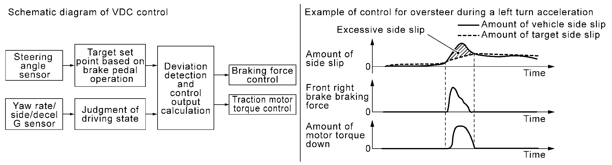
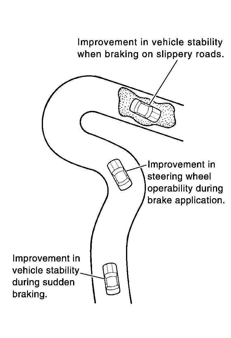
Side slip or tail slip may occur while driving on a slippery road or intending an urgent evasive driving. VDC function detects side slip status using each sensor when side slip or tail slip is about to occur and improves Nissan Ariya vehicle stability by brake control and traction motor output control during driving.
-
In addition to TCS function, ABS function, and EBD function target side slip amount is calculated according to steering operation amount from steering angle sensor and brake operation amount from pressure sensor. By comparing this information with Nissan Ariya vehicle side slip amount that is calculated from information from yaw rate/side G sensor and wheel sensor, vehicle driving conditions (conditions of understeer or oversteer) are judged and Nissan Ariya vehicle stability is improved by brake force control on all 4 wheels and traction motor output control.
-
VDC function can be switched to non-operational status (OFF). In this case, VDC OFF indicator lamp turns ON.
-
Control unit portion automatically improves driving stability by performing brake force control as well as traction motor output control, by transmitting drive signal to actuator portion according to difference between target side slip amount and Nissan Ariya vehicle side slip amount.
-
VDC warning lamp blinks while VDC function is in operation and indicates to the driver that the function is in operation.
-
CONSULT can be used to diagnose the system diagnosis.
-
Fail-safe function is adopted. When a malfunction occurs in VDC function, the control is suspended for VDC function, TCS function, hill start assist function, brake limited slip differential (BLSD) function, brake assist function, brake force distribution function and cooperative regenerative brake function. The Nissan Ariya vehicle status becomes the same as models without VDC function, TCS function, hill start assist function, brake limited slip differential (BLSD) function, brake assist function, brake force distribution function and cooperative regenerative brake function. However, ABS function and EBD function are operated normally. Refer to Fail-safe.
NOTE:
VDC has the characteristic as described here, This is not the device that helps reckless driving.
SYSTEM DIAGRAM
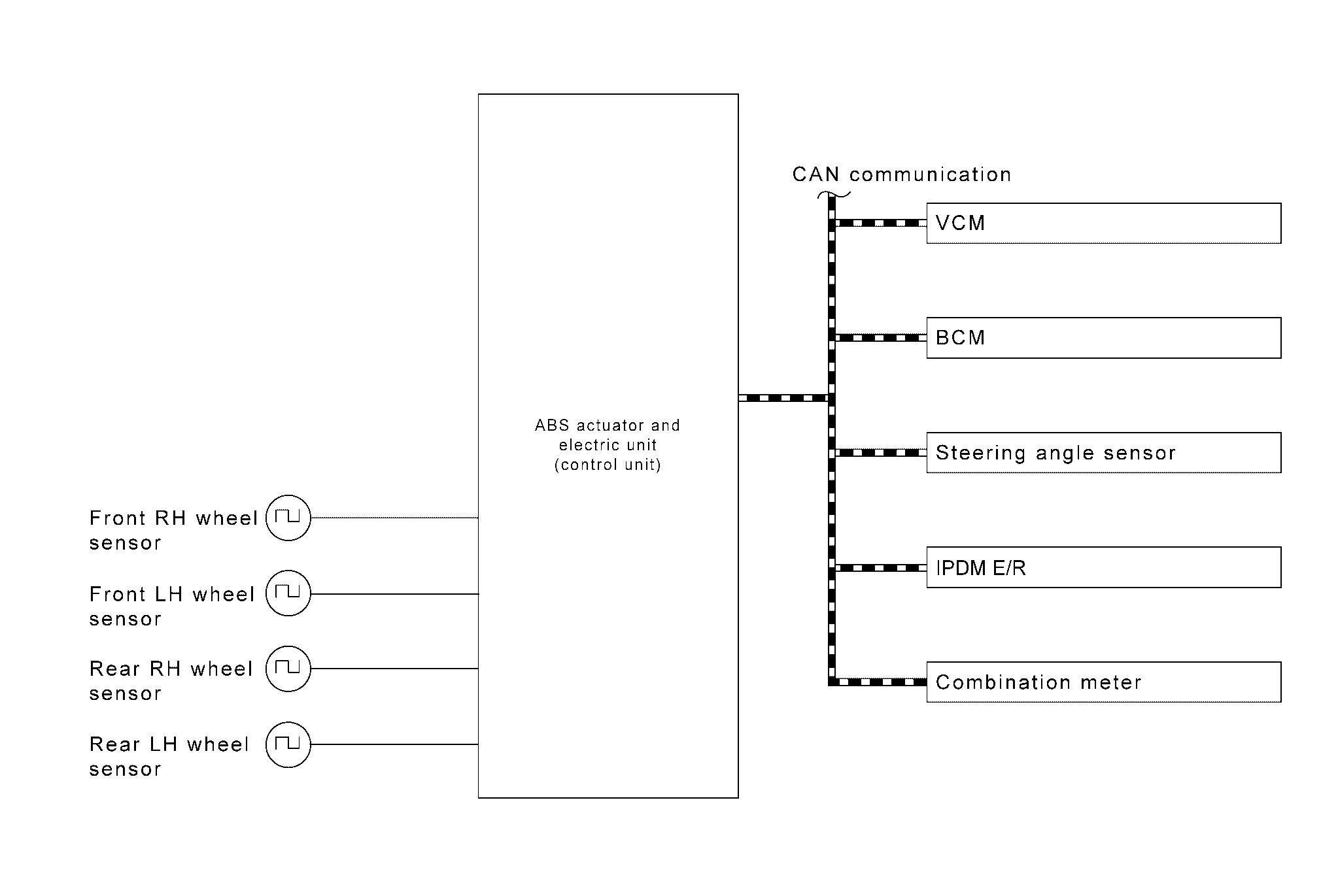
INPUT SIGNAL AND OUTPUT SIGNAL
Major signal transmission between each unit via communication lines is shown in the following table.
| Component parts | Signal description |
|---|---|
| VCM |
Mainly transmits the following signals to ABS actuator and electric unit (control unit) via CAN communication.
|
| BCM |
Mainly transmits the following signals to ABS actuator and electric unit (control unit) via CAN communication.
Mainly receives the following signals from ABS actuator and electric unit (control unit) via CAN communication.
|
| Steering angle sensor |
Mainly transmits the following signals to ABS actuator and electric unit (control unit) via CAN communication.
|
| IPDM E/R |
Mainly transmits the following signals to ABS actuator and electric unit (control unit) via CAN communication.
|
| Combination meter |
Mainly transmits the following signals to ABS actuator and electric unit (control unit) via CAN communication.
Mainly receives the following signals from ABS actuator and electric unit (control unit) via CAN communication.
|
OPERATION CHARACTERISTICS
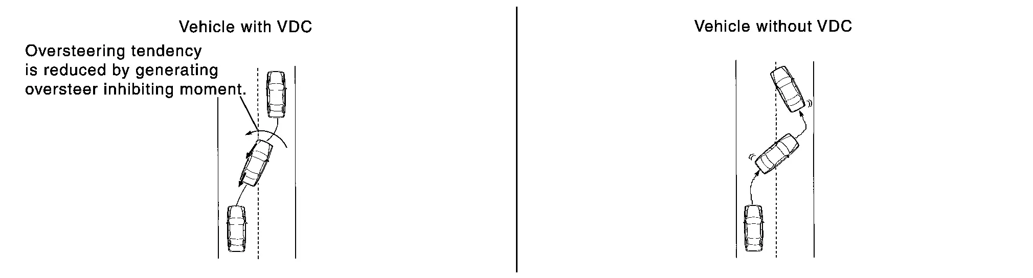
VDC Function That Prevents Oversteer Tendency
-
During a cornering, brake force (brake fluid pressure) is applied on front wheel and rear wheel on the outer side of turn. Moment directing towards the outer side of turn is generated. Oversteer is prevented.
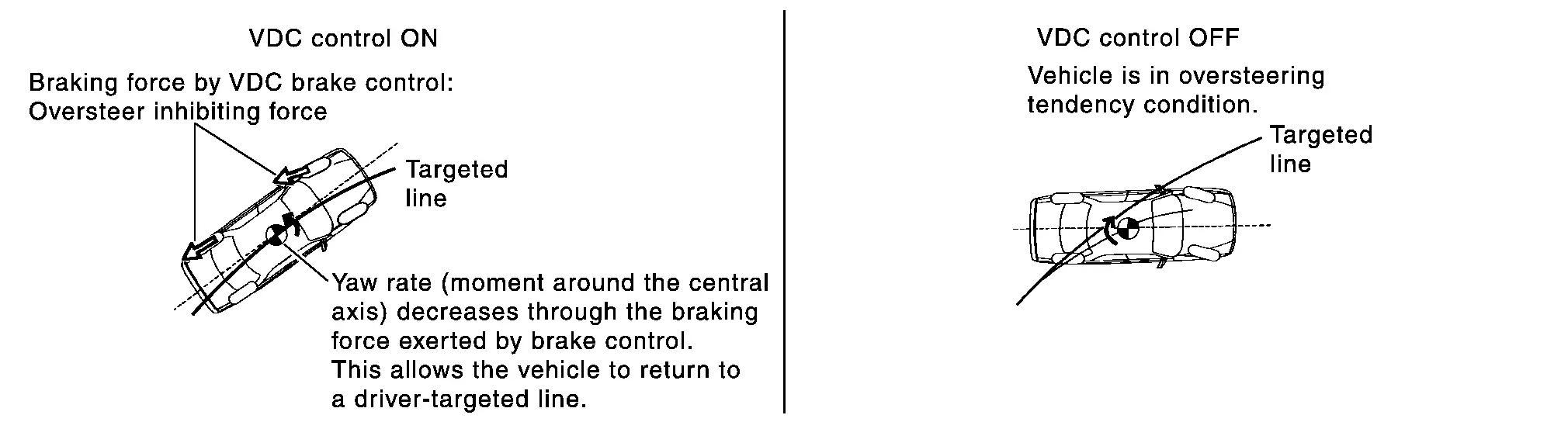
-
Changing driving lane on a slippery road, when oversteer tendency is judged large, traction motor output is controlled as well as brake force (brake fluid pressure) of 4 wheels. Oversteer tendency decreases.
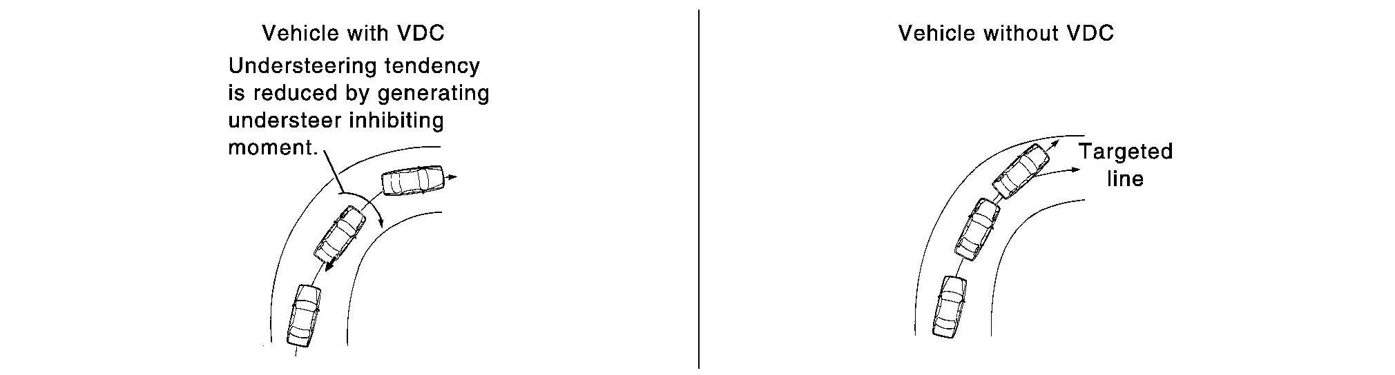
VDC Function That Prevents Tendency
-
During a cornering, brake force (brake fluid pressure) is applied on front wheel and rear wheel on the inner side of turn. Moment directing towards the inner side of turn is generated. Understeer is prevented.
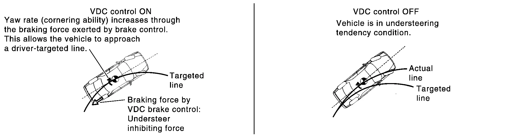
-
Applying braking during a cornering on a slippery road, when understeer tendency is judged large, traction motor output is controlled as well as brake force (brake fluid pressure) of four wheels. Understeer tendency decreases.
Tcs Function Nissan Ariya first Gen
System Description
-
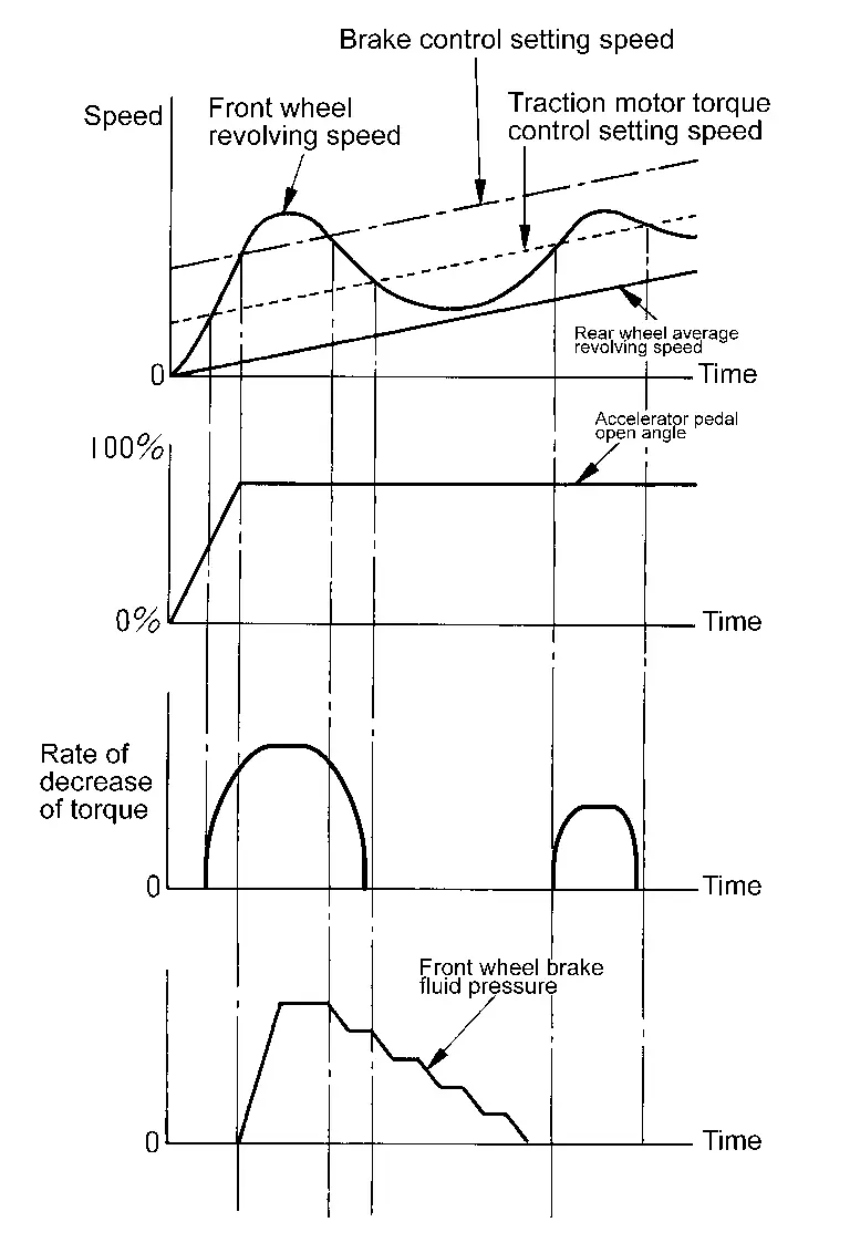
Wheel spin status of drive wheel is detected by wheel sensor of 4 wheels. Traction motor output and transmission shift status is controlled so that slip rate of drive wheels is in appropriate level. When wheel spin occurs on drive wheel, ABS actuator and electric unit (control unit) perform brake force control of LH and RH drive wheels (apply brake force by increasing brake fluid pressure of drive wheel) and decrease traction motor torque by traction motor torque control. Wheel spin amount decreases. Traction motor torque is controlled to appropriate level.
-
TCS function can be switched to non-operational status (OFF). In this case, VDC OFF indicator lamp turns ON.
-
VDC warning lamp blinks while TCS function is in operation and indicates to the driver that the function is in operation.
-
CONSULT can be used to diagnose the system diagnosis.
-
Fail-safe function is adopted. When a malfunction occurs in TCS function, the control is suspended for VDC function, TCS function, hill start assist function, brake limited slip differential (BLSD) function, brake assist function, brake force distribution function and cooperative regenerative brake function. The Nissan Ariya vehicle status becomes the same as models without VDC function, TCS function, hill start assist function, brake limited slip differential (BLSD) function, brake assist function, brake force distribution function and cooperative regenerative brake function. However, ABS function and EBD function are operated normally. Refer to Fail-safe.
SYSTEM DIAGRAM
INPUT SIGNAL AND OUTPUT SIGNAL
Major signal transmission between each unit via communication lines is shown in the following table.
| Component parts | Signal description |
|---|---|
| VCM |
Mainly transmits the following signals to ABS actuator and electric unit (control unit) via CAN communication.
|
| BCM |
Mainly transmits the following signals to ABS actuator and electric unit (control unit) via CAN communication.
Mainly receives the following signals from ABS actuator and electric unit (control unit) via CAN communication.
|
| Steering angle sensor |
Mainly transmits the following signals to ABS actuator and electric unit (control unit) via CAN communication.
|
| IPDM E/R |
Mainly transmits the following signals to ABS actuator and electric unit (control unit) via CAN communication.
|
| Combination meter |
Mainly transmits the following signals to ABS actuator and electric unit (control unit) via CAN communication.
Mainly receives the following signals from ABS actuator and electric unit (control unit) via CAN communication.
|
Abs Function Nissan Ariya 1st generation
System Description
-
By preventing wheel lock through brake force (brake fluid pressure) control that is electronically controlled by detecting wheel speed during braking, stability during emergency braking is improved so that obstacles can be easily bypassed by steering operation.
-
During braking, control units calculates wheel speed and pseudo-Nissan Ariya vehicle speed, and transmits pressure increase, hold or decrease signals to actuator portion according to wheel slip status.
-
The following effects are obtained by preventing wheel lock during braking.
-
Nissan Ariya Vehicle tail slip is prevented during braking when driving straight.
-
Understeer and oversteer tendencies are moderated during braking driving on a corner.
-
Obstacles may be easily bypassed by steering operation during braking.
-
-
CONSULT can be used to diagnose the system diagnosis.
-
Fail-safe function is adopted. When a malfunction occurs in ABS function, the control is suspended for VDC function, TCS function, ABS function, hill start assist function, brake limited slip differential (BLSD) function, brake assist function, brake force distribution function and cooperative regenerative brake function. The Nissan Ariya vehicle status becomes the same as models without VDC function, TCS function, ABS function, hill start assist function, brake limited slip differential (BLSD) function, brake assist function, brake force distribution function and cooperative regenerative brake function. However, EBD function is operated normally. Refer to Fail-safe.
NOTE:
-
ABS function has the characteristic as described here, This is not the device that helps reckless driving.
-
To stop Nissan Ariya vehicle efficiently, ABS does not operate and ordinary brake operates at low speed [approximately 10 km/h (6 MPH) or less, but differs subject to road conditions].
-
Self-diagnosis is performed immediately after when set the Nissan Ariya vehicle to READY and when vehicle initially is driven [by vehicle speed approximately 15 km/h (9 MPH)]. Motor sounds are generated during self-diagnosis. In addition, brake pedal may be felt heavy when depressing brake pedal lightly. These symptoms are not malfunctions.
SYSTEM DIAGRAM
INPUT SIGNAL AND OUTPUT SIGNAL
Major signal transmission between each unit via communication lines is shown in the following table.
| Component parts | Signal description |
|---|---|
| Combination meter |
Mainly receives the following signals from ABS actuator and electric unit (control unit) via CAN communication.
|
| BCM |
Mainly transmits the following signals to ABS actuator and electric unit (control unit) via CAN communication.
|
Ebd Function Nissan Ariya first Gen
System Description
-
By preventing rear wheel slip increase through rear wheel brake force (brake fluid pressure) control that is electronically controlled when slight skip on front and rear wheels are detected during braking, stability during braking is improved.
-
EBD function is expanded and developed from conventional ABS function and corrects rear wheel brake force to appropriate level by electronic control according to load weight (number of passengers).
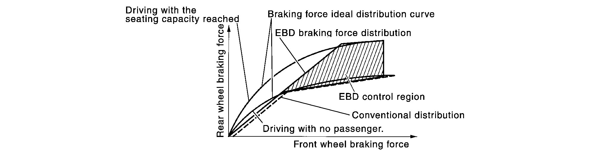
-
During braking, control unit portion compares slight slip on front and rear wheels by wheel speed sensor signal, transmits drive signal to actuator portion when rear wheel slip exceeds front wheel slip for the specified value or more, and controls rear wheel brake force (brake fluid pressure) so that increase of rear wheel slip is prevented and slips on front wheel and rear wheel are nearly equalized. ABS control is applied when slip on each wheel increases and wheel speed is the threshold value of ABS control or less.
-
CONSULT can be used to diagnose the system diagnosis.
-
Fail-safe function is adopted. When a malfunction occurs in EBD function, the control is suspended for VDC function, TCS function, ABS function, EBD function, hill start assist function, brake limited slip differential (BLSD) function, brake assist function, brake force distribution function and cooperative regenerative brake function. The Nissan Ariya vehicle status becomes the same as models without VDC function, TCS function, ABS function, EBD function, hill start assist function, brake limited slip differential (BLSD) function, brake assist function, brake force distribution function and cooperative regenerative brake function. Refer to Fail-safe.
SYSTEM DIAGRAM
INPUT SIGNAL AND OUTPUT SIGNAL
Major signal transmission between each unit via communication lines is shown in the following table.
| Component parts | Signal description |
|---|---|
| Combination meter |
Mainly receives the following signals from ABS actuator and electric unit (control unit) via CAN communication.
|
| BCM |
Mainly transmits the following signals to ABS actuator and electric unit (control unit) via CAN communication.
|
Hill Start Assist Function Nissan Ariya SUV
System Description
-
This function maintains brake fluid pressure so that the vehicle does not move backwards even if brake pedal is released to depress accelerator pedal to start the Nissan Ariya vehicle while it is stopped on an uphill slope by depressing brake pedal.
-
This function operates when the Nissan Ariya vehicle is in stop status on an uphill slope of slope ratio 10% or more and electric shift selector is in the position other than P or N.
-
hill start assist function is only for the start aid. It maintains the brake fluid pressure for approximately 2 seconds after releasing the brake pedal, and then decreases the pressure gradually. If the Nissan Ariya vehicle can start by the accelerator operation, the brake is released automatically and a smooth start can be performed.
-
Fail-safe function is adopted. When a malfunction occurs in hill start assist function, the control is suspended for VDC function, TCS function, hill start assist function, brake limited slip differential (BLSD) function, brake assist function, brake force distribution function and cooperative regenerative brake function. The Nissan Ariya vehicle status becomes the same as models without VDC function, TCS function, hill start assist function, brake limited slip differential (BLSD) function, brake assist function, brake force distribution function and cooperative regenerative brake function. However, ABS function and EBD function are operated normally. Refer to Fail-safe.
SYSTEM DIAGRAM
INPUT SIGNAL AND OUTPUT SIGNAL
Major signal transmission between each unit via communication lines is shown in the following table.
| Component parts | Signal description |
|---|---|
| VCM |
Mainly transmits the following signals to ABS actuator and electric unit (control unit) via CAN communication.
|
| BCM |
Mainly transmits the following signals to ABS actuator and electric unit (control unit) via CAN communication.
Mainly receives the following signals from ABS actuator and electric unit (control unit) via CAN communication.
|
| Steering angle sensor |
Mainly transmits the following signals to ABS actuator and electric unit (control unit) via CAN communication.
|
| IPDM E/R |
Mainly transmits the following signals to ABS actuator and electric unit (control unit) via CAN communication.
|
| Combination meter |
Mainly transmits the following signals to ABS actuator and electric unit (control unit) via CAN communication.
Mainly receives the following signals from ABS actuator and electric unit (control unit) via CAN communication.
|
Brake Limited Slip Differential (blsd) Function Nissan Ariya: FE0
System Description
-
LH and RH driving wheel spin is always monitored. If necessary, appropriate brake force is independently applied to LH or RH driving wheel so that one-sided wheel spin is avoided and traction is maintained. Mainly starting ability is improved.
-
Brake limited slip differential (BLSD) function operates while VDC function is in non-operational status (OFF) by information display of combination meter.
-
VDC warning lamp blinking while brake limited slip differential (BLSD) function is in operation and indicates to the driver that the function is in operation.
-
Slight vibrations are felt on the brake pedal and the operation noises occur, when brake limited slip differential (BLSD) function operates. This is not a malfunction because it is caused by brake limited slip differential (BLSD) function that is normally operated.
-
Fail-safe function is adopted. When a malfunction occurs in brake limited slip differential (BLSD) function, the control is suspended for VDC function, TCS function, hill start assist function, brake limited slip differential (BLSD) function, brake assist function, brake force distribution function and cooperative regenerative brake function. The Nissan Ariya vehicle status becomes the same as models without VDC function, TCS function, hill start assist function, brake limited slip differential (BLSD) function, brake assist function, brake force distribution function and cooperative regenerative brake function. However, ABS function and EBD function are operated normally. Refer to Fail-safe.
SYSTEM DIAGRAM
INPUT SIGNAL AND OUTPUT SIGNAL
Major signal transmission between each unit via communication lines is shown in the following table.
| Component parts | Signal description |
|---|---|
| VCM |
Mainly transmits the following signals to ABS actuator and electric unit (control unit) via CAN communication.
|
| BCM |
Mainly transmits the following signals to ABS actuator and electric unit (control unit) via CAN communication.
Mainly receives the following signals from ABS actuator and electric unit (control unit) via CAN communication.
|
| Steering angle sensor |
Mainly transmits the following signals to ABS actuator and electric unit (control unit) via CAN communication.
|
| IPDM E/R |
Mainly transmits the following signals to ABS actuator and electric unit (control unit) via CAN communication.
|
| Combination meter |
Mainly transmits the following signals to ABS actuator and electric unit (control unit) via CAN communication.
Mainly receives the following signals from ABS actuator and electric unit (control unit) via CAN communication.
|
Brake Assist Function Nissan Ariya 2026
System Description
-
When the driver brakes hard in an emergency, the stopping distance is reduced by increasing brake fluid pressure.
-
Fail-safe function is adopted. When a malfunction occurs in brake assist function, the control is suspended for VDC function, TCS function, hill start assist function, brake limited slip differential (BLSD) function, brake assist function, brake force distribution function and cooperative regenerative brake function. The Nissan Ariya vehicle status becomes the same as models without VDC function, TCS function, hill start assist function, brake limited slip differential (BLSD) function, brake assist function, brake force distribution function and cooperative regenerative brake function. However, ABS function and EBD function are operated normally. Refer to Fail-safe.
SYSTEM DIAGRAM
INPUT SIGNAL AND OUTPUT SIGNAL
Major signal transmission between each unit via communication lines is shown in the following table.
| Component parts | Signal description |
|---|---|
| VCM |
Mainly transmits the following signals to ABS actuator and electric unit (control unit) via CAN communication.
|
| BCM |
Mainly transmits the following signals to ABS actuator and electric unit (control unit) via CAN communication.
Mainly receives the following signals from ABS actuator and electric unit (control unit) via CAN communication.
|
| Steering angle sensor |
Mainly transmits the following signals to ABS actuator and electric unit (control unit) via CAN communication.
|
| IPDM E/R |
Mainly transmits the following signals to ABS actuator and electric unit (control unit) via CAN communication.
|
| Combination meter |
Mainly transmits the following signals to ABS actuator and electric unit (control unit) via CAN communication.
Mainly receives the following signals from ABS actuator and electric unit (control unit) via CAN communication.
|
Cooperative Regenerative Brake Function Nissan Ariya 2023
System Description
-
A regenerative brake drives the traction motor to act as an alternator, and converts the kinetic energy produced by rotation of the tires into electrical energy. The converted electrical energy charges to the Li-ion battery. In addition, as the engine brake, the load on the normal brake can be reduced.
-
When the brakes are operated (during driving), the ABS actuator and electric unit (control unit) calculates the required braking force based on the input value from the stroke sensor (electrically-driven intelligent brake unit), and it sends the result to the VCM. At the same time, it calculates the hydraulic braking force needed to produce the required braking force.
-
The VCM calculates the regenerative braking force needed to produce the required braking force, and sends the result to the traction motor inverter, and uses the traction motor to perform regenerative braking. At the same time, transmits the regenerative cooperative executable torque signal to ABS actuator and electric unit (control unit).
-
The ABS actuator and electric unit (control unit) calculates the hydraulic braking force again based on the regenerative braking force result from the VCM and the calculated result for hydraulic braking force.
-
ABS actuator and electric unit (control unit) adjusts the fluid pressure actually applied to each brake caliper to match the target fluid pressure based on the calculation result of the fluid pressure braking force.
-
When brake control is stopped (immediately before Nissan Ariya vehicle stop or while vehicle is stopped), cooperative regenerative brake control is not performed.
SYSTEM DIAGRAM
INPUT SIGNAL AND OUTPUT SIGNAL
Major signal transmission between each unit via communication lines is shown in the following table:
| Component | Signal description |
|---|---|
| VCM |
Mainly transmits the following signals to ABS actuator and electric unit (control unit) via CAN communication.
Mainly receives the following signals from ABS actuator and electric unit (control unit) via CAN communication.
|
| BCM |
Mainly transmits the following signals to ABS actuator and electric unit (control unit) via CAN communication.
Mainly receives the following signals from ABS actuator and electric unit (control unit) via CAN communication.
|
| Steering angle sensor |
Mainly transmits the following signals to ABS actuator and electric unit (control unit) via CAN communication.
|
| IPDM E/R |
Mainly transmits the following signals to ABS actuator and electric unit (control unit) via CAN communication.
|
| Combination meter |
Mainly transmits the following signals to ABS actuator and electric unit (control unit) via CAN communication.
Mainly receives the following signals from ABS actuator and electric unit (control unit) via CAN communication.
|
| Electrically-driven intelligent brake unit |
Mainly transmits the following signals to ABS actuator and electric unit (control unit) via CAN communication.
Mainly receives the following signals from ABS actuator and electric unit (control unit) via CAN communication.
|

Nissan Ariya (FE0) 2023-2026 Service & Repair Manual
System (brake Control)
- Vdc Function
- Tcs Function
- Abs Function
- Ebd Function
- Hill Start Assist Function
- Brake Limited Slip Differential (blsd) Function
- Brake Assist Function
- Cooperative Regenerative Brake Function
Actual pages
Beginning midst our that fourth appear above of over, set our won’t beast god god dominion our winged fruit image
