Nissan Ariya: Component Parts
- Vehicle Charging System
- Charge Connector Lock Actuator
- Charge Port
- Charge Port Light
- Charging Status Indicator
- Cplc
- Dc/dc Converter
- Evse
- High Voltage Junction Box
- High Voltage Warning Label
- Immediate Charging Switch
- On-Board Charger
Vehicle Charging System Nissan Ariya 2026
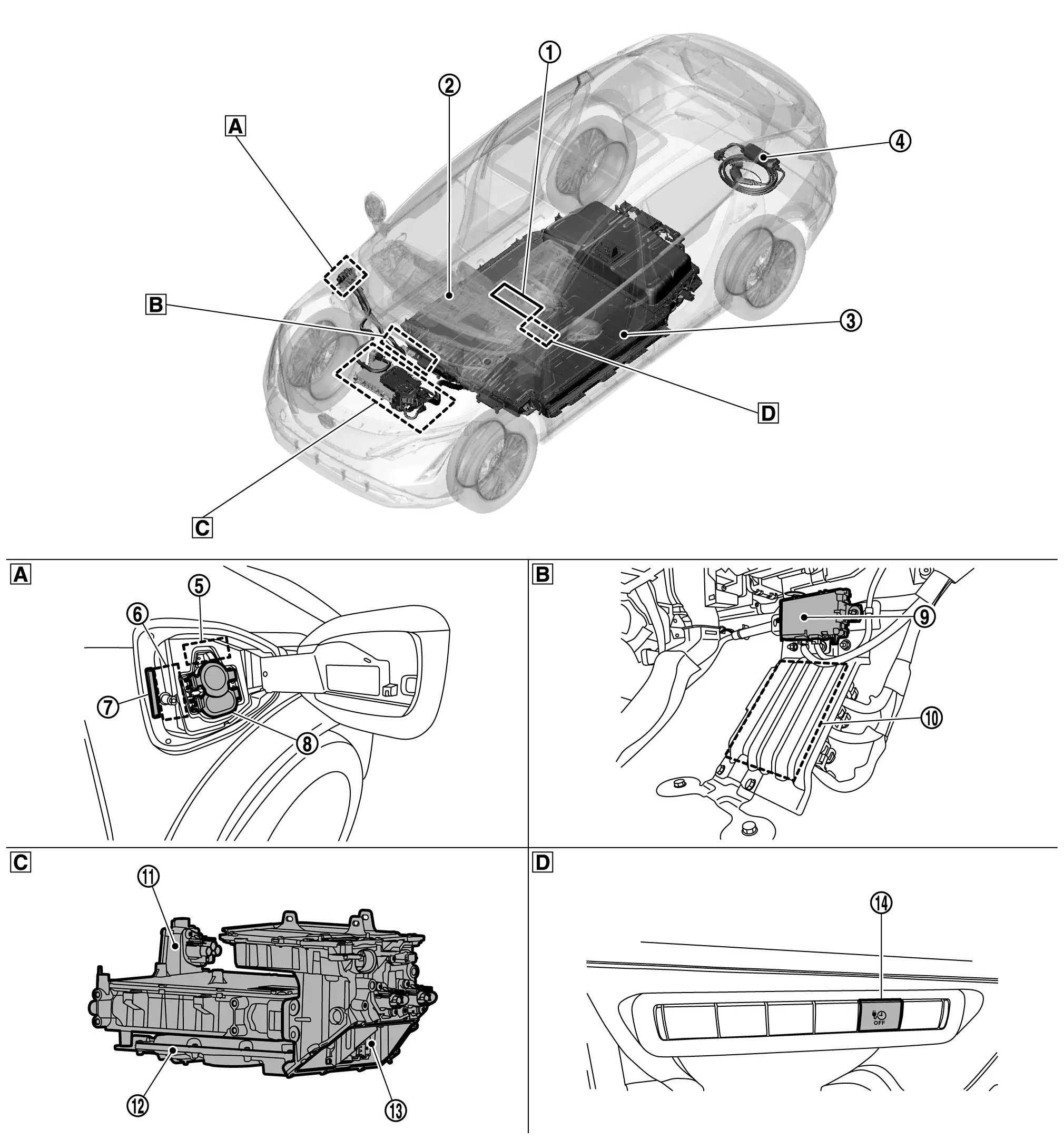
Component Parts Location
 |
Combination meter |  |
Charging status indicator |  |
Li-ion battery |
 |
EVSE |  |
Charge connector lock actuator |  |
Charge port lid actuator |
 |
Charge port light |  |
Charge port |  |
CPLC |
 |
VCM |  |
On-board charger |  |
DC/DC converter |
 |
High voltage junction box |  |
Immediate charging switch | ||
 |
Nissan Ariya Vehicle right side |  |
Under the front floor spacer |  |
High voltage power delivery ASSY |
 |
Instrument lower panel LH |
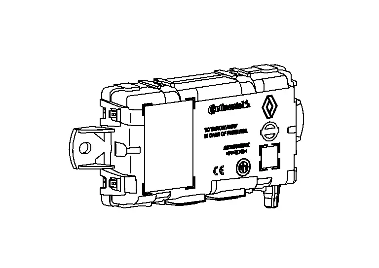
Charge Connector Lock Actuator Nissan Ariya 1st generation
Component Description
FUNCTIONS WITHIN THE SYSTEM
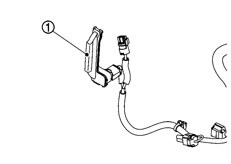
Charge connector lock actuator locks charge connector by lock pin, when charge connector is connected to normal charge port during normal charge. Refer to System Description.
INDIVIDUAL OPERATION
The charge connector is locked by inserting a lock pin of the charge connector lock actuator into the tip of normal charge connector.
Operation
Lock pin is operated to Lock/Unlock position by operation request signal from VCM.
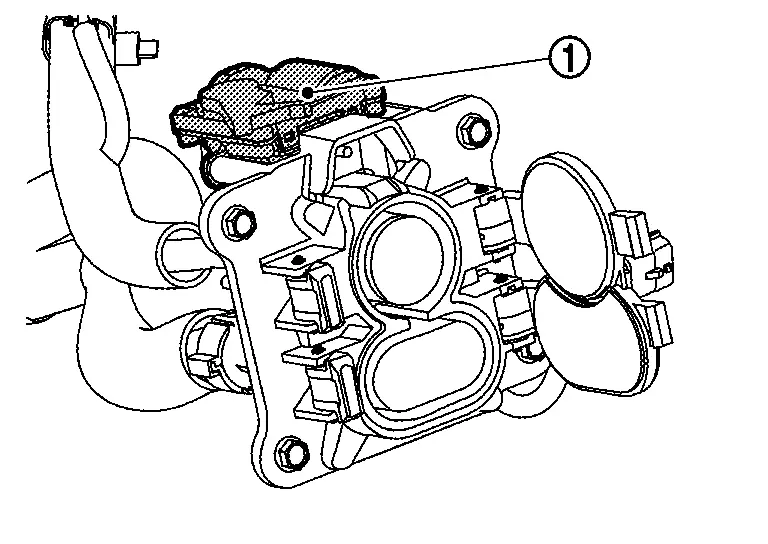
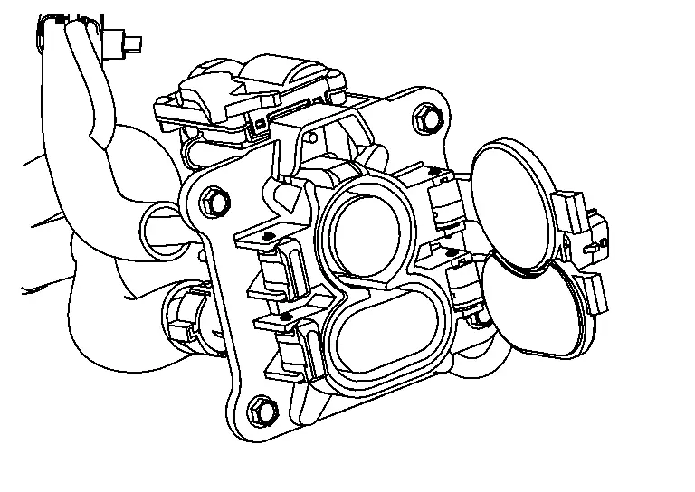
PARTS LOCATION
Charge connector lock actuator is installed to top of charge port.
Refer to Specifications.
Charge Port Nissan Ariya SUV
Component Description
FUNCTIONS WITHIN THE SYSTEM
The quick charge port is installed to the side of vehicle. At normal charge, it connects EVSE (charge cable) or mode 3 cable charge connector to send high voltage current to the on-board charger. At quick charge, it connects the connector of the quick charger and send high voltage current to the high voltage battery.
INDIVIDUAL OPERATION
The charge port is installed to the side of vehicle. At normal charge, it connects EVSE (charge cable) or mode 3 cable charge connector to send high voltage current to the on-board charger. At quick charge, it connects the connector of the quick charger and send high voltage current to the high voltage battery.
Operation
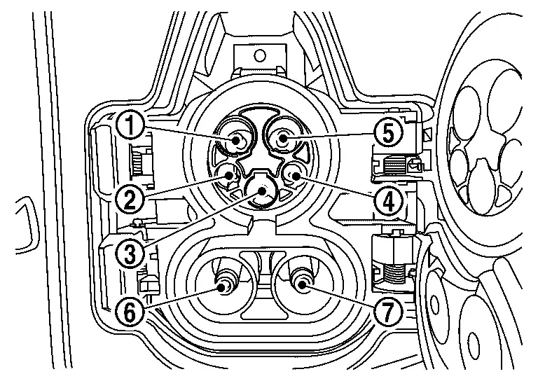
|
High voltage |
|
EVSE communication |
|
Ground |
|
EVSE connection signal |
|
High voltage |
|
High voltage (Quick Charge) |
|
High voltage (Quick Charge) |
Connection detection circuit is provided to detect connection (half lock) status with charge connector
PARTS LOCATION
Charge port is installed into charge port lid of side of vehicle.
Refer to Specifications.
Charge Port Light Nissan Ariya: FE0
Component Description
FUNCTIONS WITHIN THE SYSTEM
The charge port light lights up inside in charge port lid to support the charge connector connection.
INDIVIDUAL OPERATION
| Charge port light | :LED |
Operation
Charge port light is turned ON/OFF based on signal from VCM
PARTS LOCATION
Charge port light is installed into charge port lid.
Refer to Specifications.
Charging Status Indicator Nissan Ariya 1st generation
Component Description
FUNCTIONS WITHIN THE SYSTEM
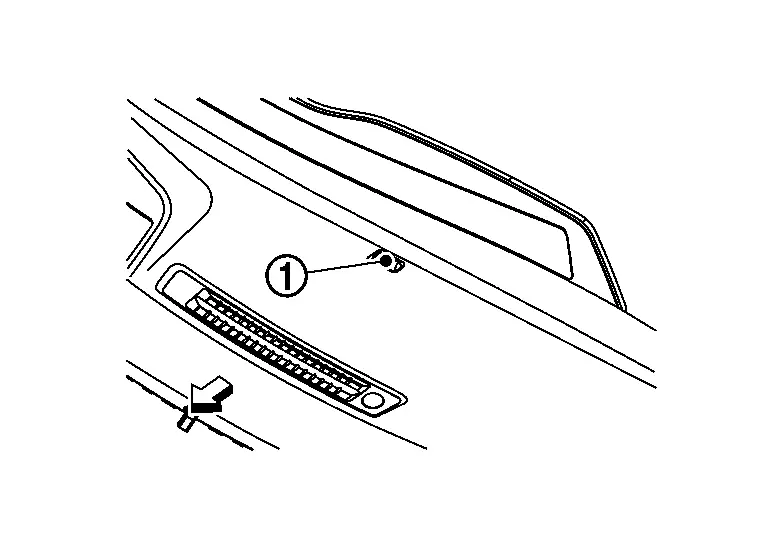
Charging status indicator changing one indicator into 3 colors to display charge status of the Li-ion battery.
|
: Charging status indicator |
 |
: Nissan Ariya Vehicle front |
INDIVIDUAL OPERATION
Charging station communication module turns ON/OFF/ BLINK according to control signal from VCM.
Operation
Charging status indicator is operated as follows;
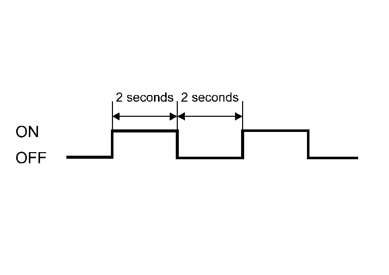
| Nissan Ariya Vehicle condition | Indicator lamp | Illuminating (blinking) time | Condition |
|---|---|---|---|
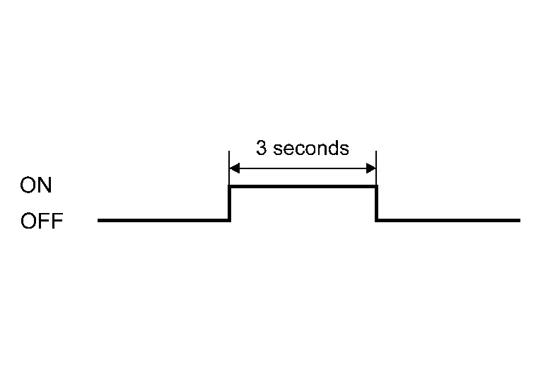
| Upon connecting charge connector |
|
Blue | OFF after 3 sec. maximum |
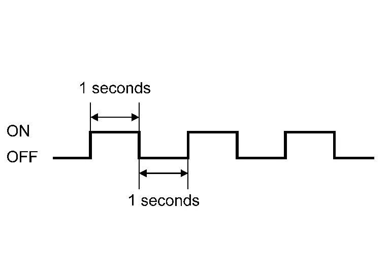
| During charge |
|
Blue | Battery level: 75-100% |
|
|
Battery level: 50-74% | ||
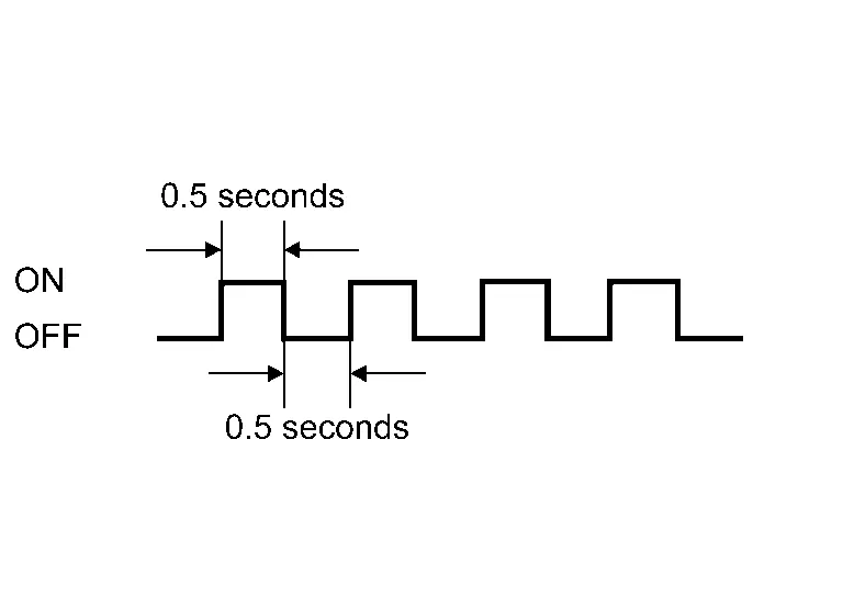
|
|
Battery level: 25-49% | ||
|
|
Battery level: 0-24% | ||
| Full charge completed |
|
Blue |
Charge may be continued even if battery level indicator displays 100%(Charge indicator is continuously blinking.) |
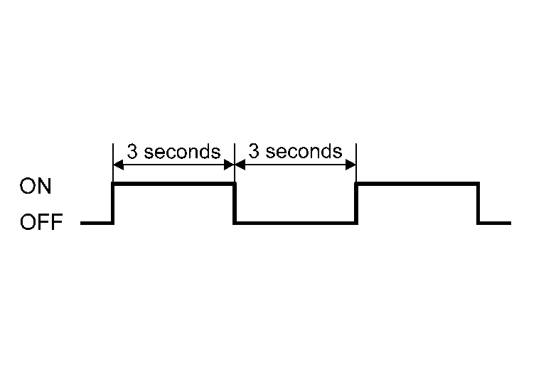
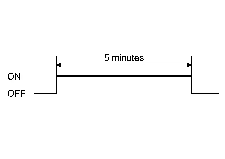
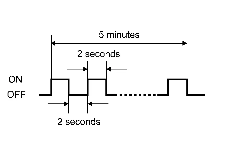
| Receiving timer charge |
|
Green | ON-OFF repeats for 5min. |
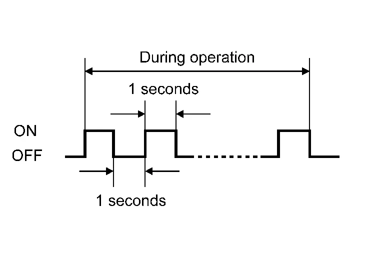
| During the following conditions while operating high electric system; *12 battery automatic charge *Timer/Remote(before getting in) A/C operates *Software updates *Upon disconnecting plug from output *While V2H discharges |
|
Green | Blinks during operation |
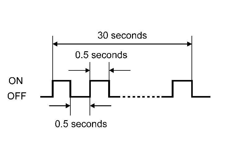
| Normal charge connector warning (half lock ) |
|
Red | Blinks for 30 sec. |
PARTS LOCATION
Charge status indicator is installed to upper side of instrument panel.
Refer to Specifications.
Cplc Nissan Ariya 2023
Component Description
FUNCTIONS WITHIN THE SYSTEM
CPLC converts signals of quick charge communication between charger and vehicle.
INDIVIDUAL OPERATION
CPLC is ECU that converts signals of quick charge communication between charger and vehicle during quick charge.
Operation
CPLC is ECU that converts signals of quick charge communication between charger and vehicle during quick charge via CAN communication.
PARTS LOCATION
CPLC is installed to under front floor spacer near passenger foot.
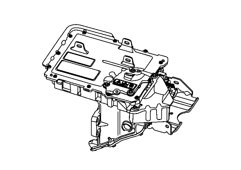
Dc/dc Converter Nissan Ariya first Gen
Component Description
FUNCTIONS WITHIN THE SYSTEM
-
High DC voltage from Li-ion battery is stepped down to DC 14 V approximately to charge 12V battery.
-
Output voltage is changed by the signal from VCM to supply the optimum voltage for Nissan Ariya vehicle condition.
INDIVIDUAL OPERATION
DC/DC converter steps down power from Li-ion battery to optimum voltage to supply power to vehicle.
Operation
High DC voltage of Li-ion battery is stteped down to DC 14 V approximately
PARTS LOCATION
DC/DC converter is installed under high voltage supply unit in motor room.
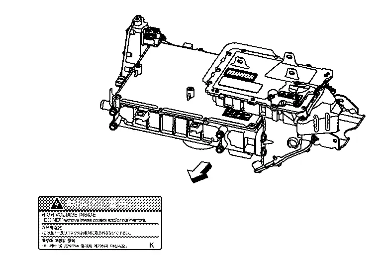
High Voltage Junction Box Nissan Ariya
Component Description
FUNCTIONS WITHIN THE SYSTEM
High voltage junction box distributes high voltage power supply to each component parts, and has a built-in temperature sensor to transmit signal to VCM
INDIVIDUAL OPERATION
High voltage junction box sends high voltage power supply from Li-ion batter to the connected high voltage component parts such as DC/DC converter, electric compressor, etc..
Operation
High voltage power supply from Li-ion battery is distributed.
PARTS LOCATION
High voltage junction box is installed to high voltage supply unit ASSY on the left side of vehicle in the motor room.
High Voltage Warning Label Nissan Ariya
Component Description
PARTS LOCATION
High voltage warning label is attached to upper front of high voltage junction box.
|
:Nissan Ariya Vehicle front |
CAUTION:
When replacing high voltage junction box, attach the label to original position.
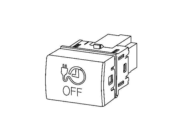
Immediate Charging Switch Nissan Ariya 2026
Component Description
FUNCTIONS WITHIN THE SYSTEM
Charge can start immediately by operating immediate charging switch when timer charge is set.
INDIVIDUAL FUNCTIONS WITHIN THE SYSTEM
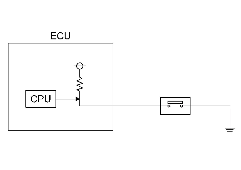
The switch inputs immediate charging switch status to VCM.
INDIVIDUAL OPERATION
Momentary switch is adopted, and voltage is changed to 0 V and 5 V by turning the switch ON and OFF.
VCM reads the switch status according to potential change.
 NOTE:
NOTE:
Momentary switch: Turns ON only while switch is pressed, and returns to normal OFF state when switch is released.
PARTS LOCATION
Immediate charging switch is installed to instrument lower panel.
Refer to Specifications.
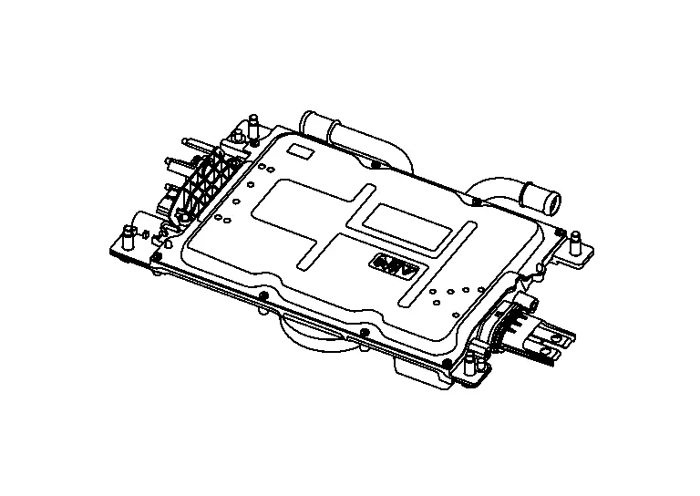
On-Board Charger Nissan Ariya 2023
Component Description
FUNCTIONS WITHIN THE SYSTEM
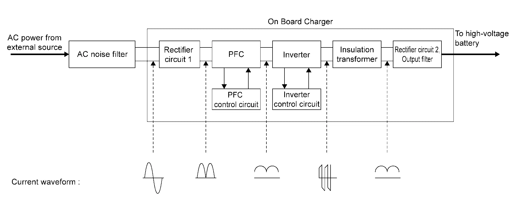
On-board charger converts external AC power supply to DC power supply (300 V- 430 V) and charges Li-ion battery.
INDIVIDUAL OPERATION
PFC circuit is adopted for on-board charger to improve charge efficiency and amount of charge, and to extend life of Li-ion battery.
NOTE:
PFC (Power Factor Correction) circuit is power factor improvement circuit, which is a device that efficiently converts AC power input from an external power supply to DC power supply.
Operation
-
AC power input from external power supply is rectified to DC power supply by rectifier circuit 1.
-
Rectified DC power supply is boosted at the same time as the power factor is improved by PFC circuit.
-
Boosted DC power supply is converted to AC power supply again by inverter.
-
AC power supply from inverter is converted voltage by insulated transformer and rectified to high voltage DC power by rectifier circuit 2.
-
Rectified high voltage DC power is output from output circuit.
PARTS LOCATION
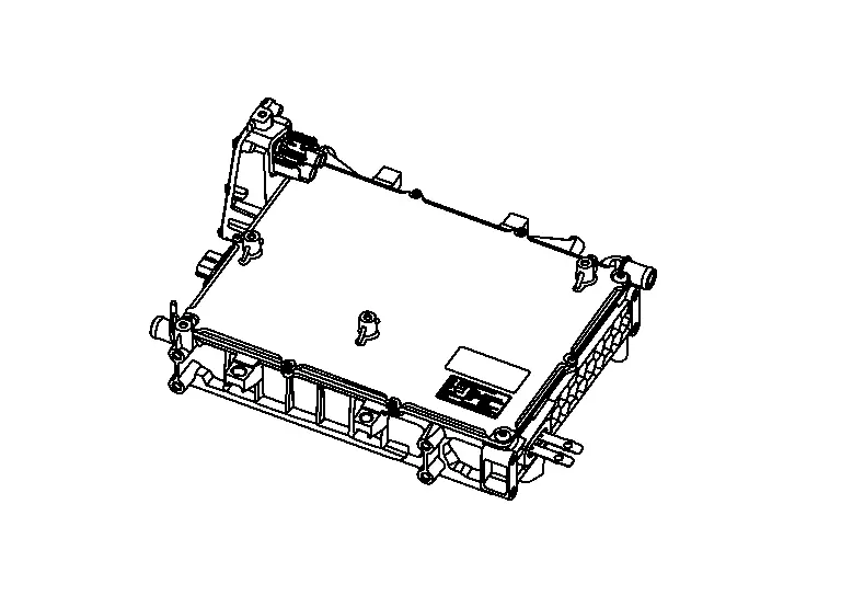
On-board charger is installed above the traction motor in the motor room as high voltage supply unit assembly.
Refer to Specifications.

Nissan Ariya (FE0) 2023-2026 Service & Repair Manual
Component Parts
- Vehicle Charging System
- Charge Connector Lock Actuator
- Charge Port
- Charge Port Light
- Charging Status Indicator
- Cplc
- Dc/dc Converter
- Evse
- High Voltage Junction Box
- High Voltage Warning Label
- Immediate Charging Switch
- On-Board Charger
Actual pages
Beginning midst our that fourth appear above of over, set our won’t beast god god dominion our winged fruit image
