Nissan Ariya: System
2wd Nissan Ariya 2023
System Description
SYSTEM DIAGRAM
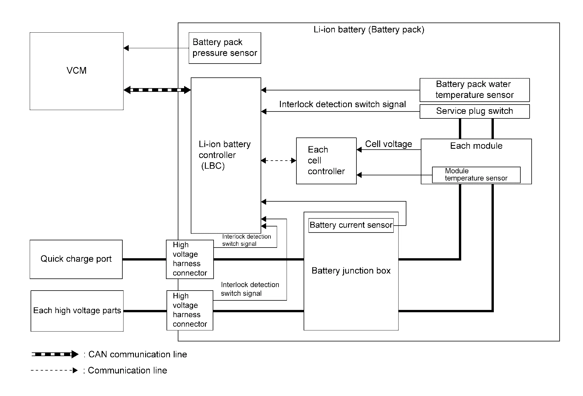
| Component | Function | |
|---|---|---|
| Li-ion battery | Li-ion battery | Refer to Component Description. |
| Module | Refer to Component Description. | |
| Li-ion battery controller (LBC) | Refer to Component Description. | |
| Cell controller | Refer to Component Description. | |
| Battery junction box | Refer to Component Description. | |
| Battery current sensor | Refer to Component Description. | |
| Battery pack pressure sensor | Refer to Component Description. | |
| Battery pack water temperature sensor | Refer to Component Description. | |
| Service plug switch | Refer to Component Description. | |
| VCM |
|
|
| Each high voltage parts | Li-ion battery controller (LBC) measures the insulation resistance of each high voltage part | |
INPUT/OUTPUT SIGNAL ITEM
Input Signal Item
| Transmission unit | Signal name | Description | |
|---|---|---|---|
| VCM | CAN communication | 12V battery voltage signal | Receives the 12V battery voltage value |
| EVSE charge status signal | Receives the charge status by EVSE | ||
| HV sleep wake up signal | Receives the sleep and the wake up request | ||
| HV battery relay status signal | Receives each relay state of the Li-ion battery | ||
| HV battery electric water pump status signal | Receives the operating status of electric water pump 2 (Li-ion battery). | ||
| Odometer signal | Receives odometer information | ||
| Nissan Ariya Vehicle speed signal | Receives vehicle speed | ||
| Charge type signal | Receives the charge type to Li-ion battery | ||
| Power switch ON signal | Receives the power switch status | ||
| Nissan Ariya Vehicle life total time signal | Receives the information of the total time after the Nissan Ariya vehicle is produced. And LBC calculates aging degradation of the battery and the battery SOH (State Of Health). | ||
Output Signal Item
| Reception unit | Signal name | Description | |
|---|---|---|---|
| VCM | CAN communication | DTC signal | Transmits DTC information of LBC |
| HV sleep-ready signal | Transmits the condition that LBC is ready to go to sleep | ||
| HV battery SOC signal | Transmits the SOC (State Of Charge) of Li-ion battery | ||
| HV battery SOH signal | Transmits the SOH (State Of Health) of Li-ion battery | ||
| HV battery interlock detection switch signal | Transmits the condition of each interlock detection switch of Li-ion battery | ||
| HV battery warning lamp request signal | Transmits warning lamp illumination request from LBC | ||
| HV battery chargeable/regeneratable power signal | Transmits the chargeable power and the regenerative charging power of Li-ion battery | ||
| HV battery condition signal | Transmits the control condition of Li-ion battery | ||
| HV battery water temperature signal | Transmits a water temperature status of the Li-ion battery | ||
| HV battery cell voltage information signal | Transmits cell voltage value of the Li-ion battery | ||
| HV battery total voltage signal | Transmits total voltage value of the Li-ion battery | ||
| HV battery current signal | Transmits a current value of the Li-ion battery | ||
| HV battery module temperature signal | Transmits each module temperature of the Li-ion battery | ||
| HV battery capacity signal | Transmits capacity of the Li-ion battery | ||
| HV battery relay ON permit signal | Transmits the state that each relay of the battery can be connected | ||
| HV battery temperature signal | Transmits a temperature state of the Li-ion battery | ||
| HV battery charge completion signal | Transmits the charge completion of the Li-ion battery | ||
| HV battery dischargeable power signal | Transmits the electricity level that lithium ion battery can discharge. | ||
| LBC temperature signal | Transmits the temperature state of LBC1 (CPU) | ||
| Outside Nissan Ariya vehicle battery charger mode signal | Transmits the mode state by the charge from outside Nissan Ariya vehicle battery charger | ||
| Insulation resistance signal | Transmits the insulation resistance of high voltage circuit | ||
| Quick charge relay controller state signal | Transmits the malfunction state of the quick charge relay controller | ||
| AV C/U | HV battery cell voltage information signal | Transmits cell voltage value of the Li-ion battery | |
| HV battery module temperature signal | Transmits each module temperature of the Li-ion battery | ||
DESCRIPTION
The Li-ion battery controller (LBC) monitors the status of the inside of the Li-ion battery at all times and transmits the information such as the charging status of Li-ion battery and possible power via CAN communication.
The Li-ion battery controller performs control as per the following.
-
Monitors the battery state and transfers chargeable/dischargeable power to VCM to prevent an error, such as overvoltage, over discharge or excessive temperature rise in the battery.
-
Detects an error (over voltage, over discharge, over current, or excessive temperature rise) immediately at the time of error occurrence and requests VCM to disconnect the system main relay to interrupt the discharge/charge line.
-
Maintains the optimum battery state constantly with a cell capacity adjustment function to prevent a reduction in charging/discharging capacity caused by cell capacity variations.
-
Detects the connector fit state with the function to detect the fit of the high voltage harness connector and transfers the detected state to VCM so that the Nissan Ariya vehicle does not start with an unsteady state.
-
Detects the insulation resistance state with the function to detect the insulation resistance between high and low voltage and transfers the detected state to VCM so that the Nissan Ariya vehicle does not start with an unusual state.
-
Estimates a battery charge state and low battery state, based on the data obtained with the battery state detection function, and reflects on the battery capacity meter.
BATTERY PROTECTION
The Li-ion battery has a voltage range capable of charge/discharge. If charged/discharged exceeding the range, excessive low capacity or malfunction may be caused. To prevent this, the Li-ion battery controller detects voltage of each cell and requests the control of charging/discharging energy to VCM so that the cell voltage stays within the voltage range.
| Control item | Control | Operating condition |
|---|---|---|
| Overvoltage/overcurrent protection | Charging energy control | Gradual control of charging energy as the cell voltage approaches the upper limit of the voltage capable of charging. |
| System main relay cut | Cell voltage exceeds the voltage judged as overvoltage and maintains the voltage for more than the specified time. | |
| Over discharge protection | Discharging energy control | Gradual control of discharging energy as the cell voltage approaches the lower limit of the voltage capable of discharging. |
| System main relay cut | Cell voltage exceeds the voltage judged as over discharge and maintains the voltage for more than the specified time. | |
| Excessive temperature rise protection | Charging/discharging energy control | Gradual control of charging/discharging energy as Li-ion battery temperature approaches the upper limit of the temperature capable of use. |
| System main relay cut | Li-ion battery temperature exceeds the temperature judged as excessive temperature rise and maintains the temperature for more than the specified time. |
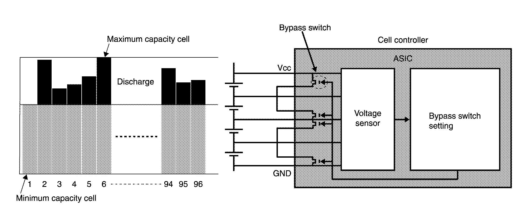
HOW TO ADJUST CELL CAPACITY
During cell capacity adjustment, the capacity of each cell is estimated based on the no-load voltage when the system starts, and the capacities are adjusted so that they are all at the target level. The voltage of each cell is detected by each cell controller. The bypass switches are then turned ON to discharge the cells that have excess capacity. In this way, capacity adjustment by each cell controller allows the capacity of all cells to be fully utilized.
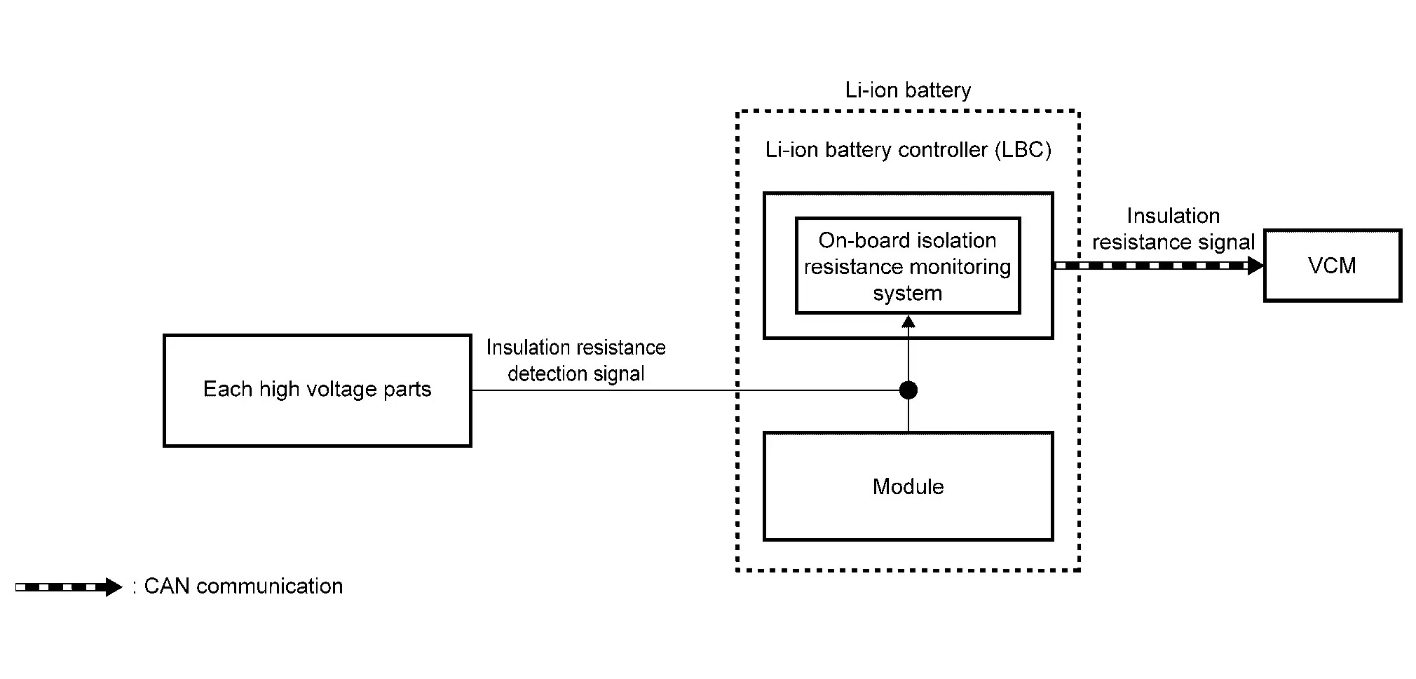
INSULATION RESISTANCE LOSS DETECTION FUNCTION
The insulation resistance detection circuit mounted inside the Li-ion battery controller measures the insulation resistance of each high voltage part and sends the measurement results to VCM via CAN communication.
VCM judges abnormal insulation resistance in each high voltage part, based on the received insulation resistance value.
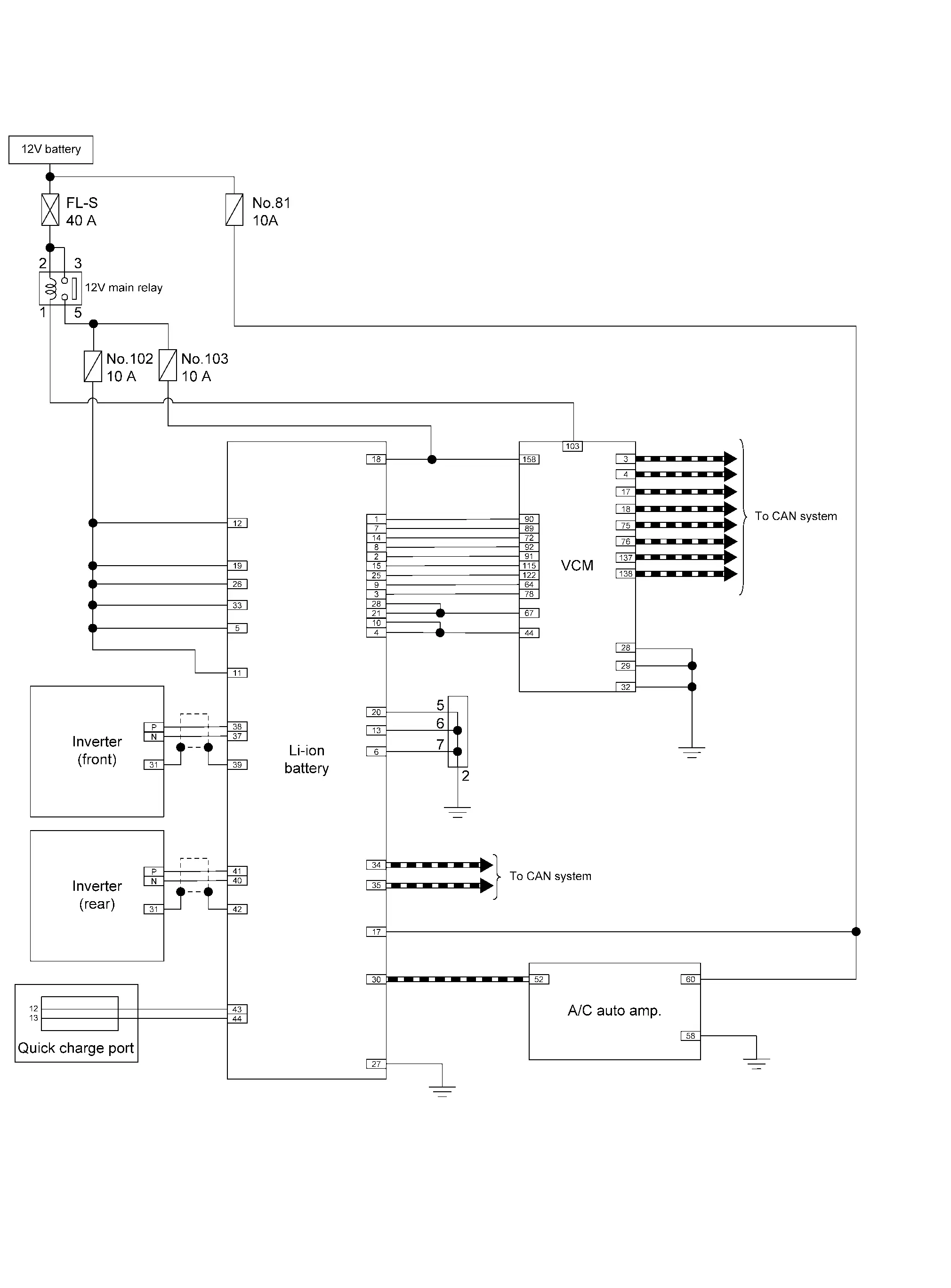
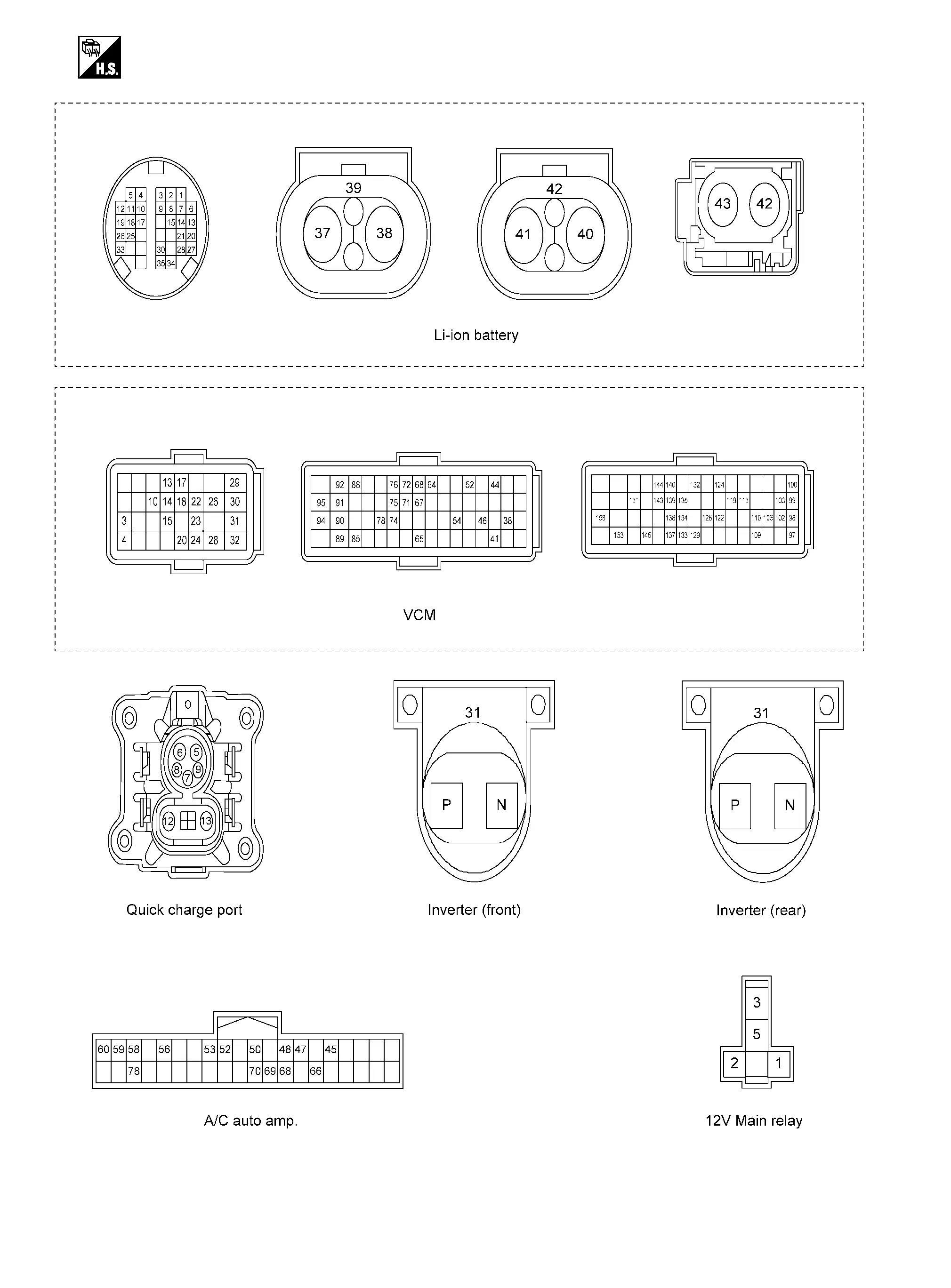
Circuit Diagram
VEHCLE SIDE
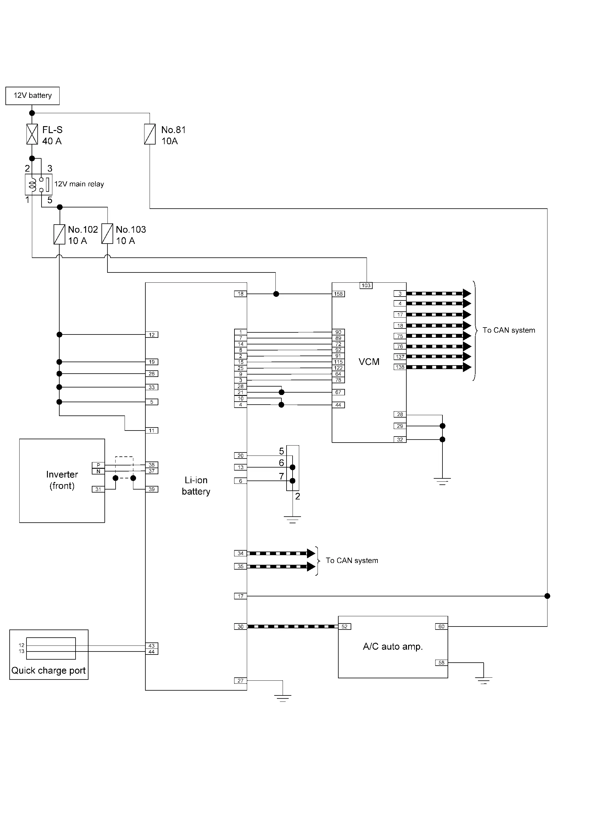
EV BATTERY PACK INTERNAL CIRCUIT
Click link to Wiring Diagram.
Harness Layout
Click link to Harness Layout.
Awd Nissan Ariya SUV
System Description
SYSTEM DIAGRAM
TYPE A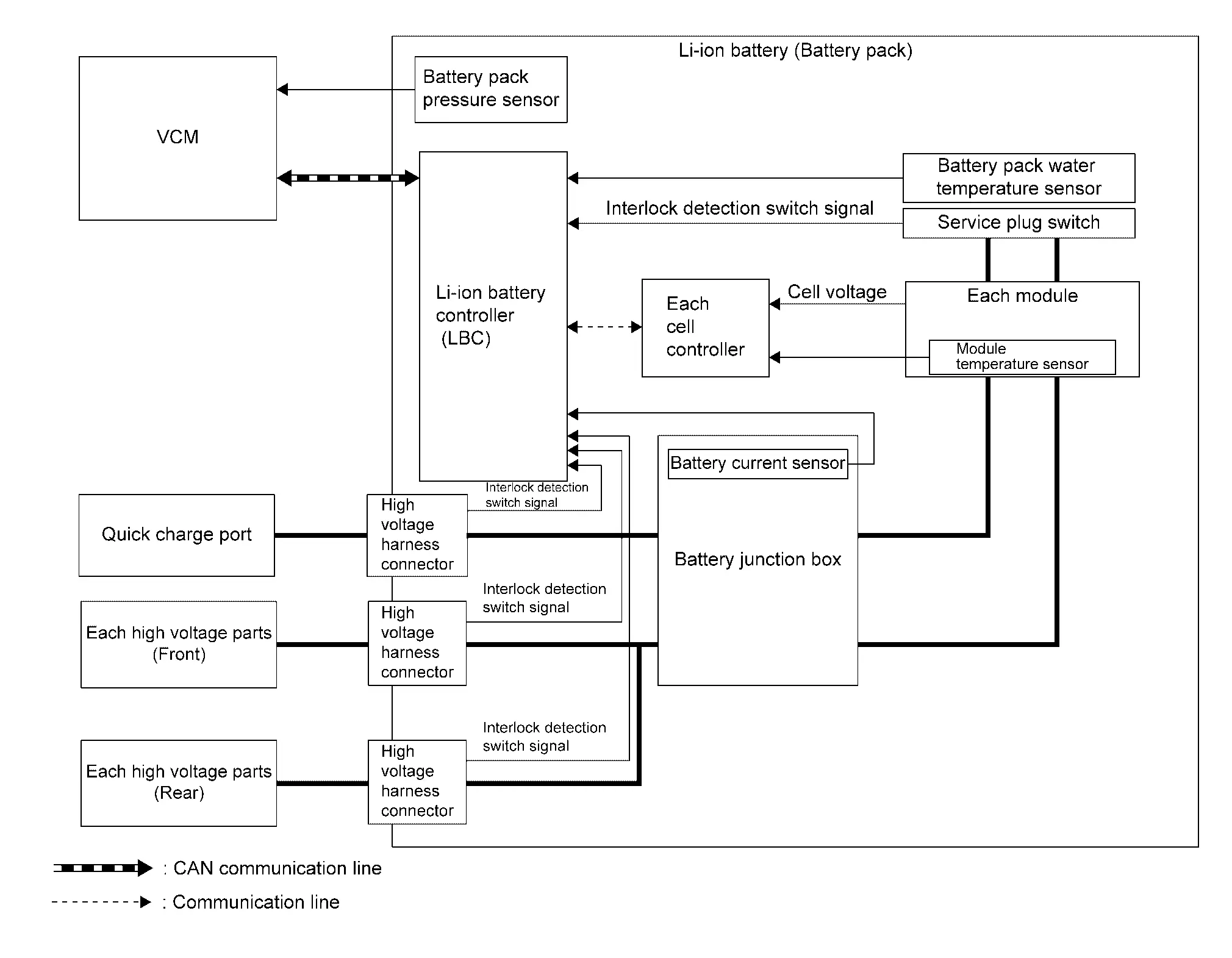
TYPE B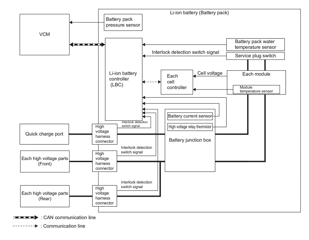
| Component | Function | |
|---|---|---|
| Li-ion battery | Li-ion battery | Refer to Component Description. |
| Module | Refer to Component Description. | |
| Li-ion battery controller (LBC) | Refer to Component Description. | |
| Cell controller | Refer to Component Description. | |
| Battery junction box | Refer to Component Description. | |
| Battery current sensor | Refer to Component Description. | |
| Battery pack pressure sensor | Refer to Component Description. | |
| Battery pack water temperature sensor | Refer to Component Description. | |
| Service plug switch | Refer to Component Description. | |
| VCM |
|
|
| Each high voltage parts | Li-ion battery controller (LBC) measures the insulation resistance of each high voltage part | |
INPUT/OUTPUT SIGNAL ITEM
Input Signal Item
| Transmission unit | Signal name | Description | |
|---|---|---|---|
| VCM | CAN communication | 12V battery voltage signal | Receives the 12V battery voltage value |
| EVSE charge status signal | Receives the charge status by EVSE | ||
| HV sleep wake up signal | Receives the sleep and the wake up request | ||
| HV battery relay status signal | Receives each relay state of the Li-ion battery | ||
| HV battery electric water pump status signal | Receives the operating status of electric water pump 2 (Li-ion battery). | ||
| Odometer signal | Receives odometer information | ||
| Nissan Ariya Vehicle speed signal | Receives vehicle speed | ||
| Charge type signal | Receives the charge type to Li-ion battery | ||
| Power switch ON signal | Receives the power switch status | ||
| Nissan Ariya Vehicle life total time signal | Receives the information of the total time after the Nissan Ariya vehicle is produced. And LBC calculates aging degradation of the battery and the battery SOH (State Of Health). | ||
Output Signal Item
| Reception unit | Signal name | Description | |
|---|---|---|---|
| VCM | CAN communication | DTC signal | Transmits DTC information of LBC |
| HV sleep-ready signal | Transmits the condition that LBC is ready to go to sleep | ||
| HV battery SOC signal | Transmits the SOC (State Of Charge) of Li-ion battery | ||
| HV battery SOH signal | Transmits the SOH (State Of Health) of Li-ion battery | ||
| HV battery interlock detection switch signal | Transmits the condition of each interlock detection switch of Li-ion battery | ||
| HV battery warning lamp request signal | Transmits warning lamp illumination request from LBC | ||
| HV battery chargeable/regeneratable power signal | Transmits the chargeable power and the regenerative charging power of Li-ion battery | ||
| HV battery condition signal | Transmits the control condition of Li-ion battery | ||
| HV battery water temperature signal | Transmits a water temperature status of the Li-ion battery | ||
| HV battery cell voltage information signal | Transmits cell voltage value of the Li-ion battery | ||
| HV battery total voltage signal | Transmits total voltage value of the Li-ion battery | ||
| HV battery current signal | Transmits a current value of the Li-ion battery | ||
| HV battery module temperature signal | Transmits each module temperature of the Li-ion battery | ||
| HV battery capacity signal | Transmits capacity of the Li-ion battery | ||
| HV battery relay ON permit signal | Transmits the state that each relay of the battery can be connected | ||
| HV battery temperature signal | Transmits a temperature state of the Li-ion battery | ||
| HV battery charge completion signal | Transmits the charge completion of the Li-ion battery | ||
| HV battery dischargeable power signal | Transmits the electricity level that lithium ion battery can discharge. | ||
| LBC temperature signal | Transmits the temperature state of LBC1 (CPU) | ||
| Outside Nissan Ariya vehicle battery charger mode signal | Transmits the mode state by the charge from outside Nissan Ariya vehicle battery charger | ||
| Insulation resistance signal | Transmits the insulation resistance of high voltage circuit | ||
| Quick charge relay controller state signal | Transmits the malfunction state of the quick charge relay controller | ||
| AV C/U | HV battery cell voltage information signal | Transmits cell voltage value of the Li-ion battery | |
| HV battery module temperature signal | Transmits each module temperature of the Li-ion battery | ||
DESCRIPTION
The Li-ion battery controller (LBC) monitors the status of the inside of the Li-ion battery at all times and transmits the information such as the charging status of Li-ion battery and possible power via CAN communication.
The Li-ion battery controller performs control as per the following.
-
Monitors the battery state and transfers chargeable/dischargeable power to VCM to prevent an error, such as overvoltage, over discharge or excessive temperature rise in the battery.
-
Detects an error (over voltage, over discharge, over current, or excessive temperature rise) immediately at the time of error occurrence and requests VCM to disconnect the system main relay to interrupt the discharge/charge line.
-
Maintains the optimum battery state constantly with a cell capacity adjustment function to prevent a reduction in charging/discharging capacity caused by cell capacity variations.
-
Detects the connector fit state with the function to detect the fit of the high voltage harness connector and transfers the detected state to VCM so that the Nissan Ariya vehicle does not start with an unsteady state.
-
Detects the insulation resistance state with the function to detect the insulation resistance between high and low voltage and transfers the detected state to VCM so that the Nissan Ariya vehicle does not start with an unusual state.
-
Estimates a battery charge state and low battery state, based on the data obtained with the battery state detection function, and reflects on the battery capacity meter.
BATTERY PROTECTION
The Li-ion battery has a voltage range capable of charge/discharge. If charged/discharged exceeding the range, excessive low capacity or malfunction may be caused. To prevent this, the Li-ion battery controller detects voltage of each cell and requests the control of charging/discharging energy to VCM so that the cell voltage stays within the voltage range.
| Control item | Control | Operating condition |
|---|---|---|
| Overvoltage/overcurrent protection | Charging energy control | Gradual control of charging energy as the cell voltage approaches the upper limit of the voltage capable of charging. |
| System main relay cut | Cell voltage exceeds the voltage judged as overvoltage and maintains the voltage for more than the specified time. | |
| Over discharge protection | Discharging energy control | Gradual control of discharging energy as the cell voltage approaches the lower limit of the voltage capable of discharging. |
| System main relay cut | Cell voltage exceeds the voltage judged as over discharge and maintains the voltage for more than the specified time. | |
| Excessive temperature rise protection | Charging/discharging energy control | Gradual control of charging/discharging energy as Li-ion battery temperature approaches the upper limit of the temperature capable of use. |
| System main relay cut | Li-ion battery temperature exceeds the temperature judged as excessive temperature rise and maintains the temperature for more than the specified time. |
HOW TO ADJUST CELL CAPACITY
During cell capacity adjustment, the capacity of each cell is estimated based on the no-load voltage when the system starts, and the capacities are adjusted so that they are all at the target level. The voltage of each cell is detected by each cell controller. The bypass switches are then turned ON to discharge the cells that have excess capacity. In this way, capacity adjustment by each cell controller allows the capacity of all cells to be fully utilized.
INSULATION RESISTANCE LOSS DETECTION FUNCTION
The insulation resistance detection circuit mounted inside the Li-ion battery controller measures the insulation resistance of each high voltage part and sends the measurement results to VCM via CAN communication.
VCM judges abnormal insulation resistance in each high voltage part, based on the received insulation resistance value.
Circuit Diagram
VEHCLE SIDE
EV BATTERY PACK INTERNAL CIRCUIT
Click link to Wiring Diagram.
Harness Layout
Click link to Harness Layout.
Fail-safe
When Li-ion Battery Controller (LBC) detects a malfunction of the Li-ion battery, it enters the control mode to protect Li-ion battery by stopping or limiting the power supply and charging from Li-ion battery.
Since fail-safe mode differs depending on the contents of the detected DTC and vehicle condition, the combination of fail-safe patterns is performed.
-
Pattern A: No driving, Charge stop, and EV system warning lamp illuminate
-
Pattern B: Driving output power limit, Charge stop, and EV system warning lamp illuminate
-
Pattern C: Driving output power limit, Charge limit, and EV system warning lamp illuminate
-
Pattern D: EV system warning lamp illuminate
-
Pattern E: Quick charge stop and EV system warning lamp illuminate
-
Pattern F: Driving output power limit, and EV system warning lamp illuminate
-
Pattern G: Charge limit, and EV system warning lamp illuminate
| DTC | CONSULT screen items | Pattern | None | ||||||
|---|---|---|---|---|---|---|---|---|---|
| A | B | C | D | E | F | G | |||
| P1B00-16 | Power supply voltage | X | |||||||
| P1B01-12 | Cell voltage circuit | X | |||||||
| P1B01-13 | Cell voltage circuit | X | |||||||
| P1B01-62 | Cell voltage circuit | X | |||||||
| P1B01-F1 | Cell voltage circuit | X | |||||||
| P1B01-F2 | Cell voltage circuit | X | |||||||
| P1B03-01 | Current sensor | X | |||||||
| P1B04-11 | Module temperature sensor | X | |||||||
| P1B04-15 | Module temperature sensor | X | |||||||
| P1B04-62 | Module temperature sensor | X | |||||||
| P1B05-11 | Module temperature sensor | X | |||||||
| P1B05-15 | Module temperature sensor | X | |||||||
| P1B05-62 | Module temperature sensor | X | |||||||
| P1B07-11 | Water temperature sensor A | X | |||||||
| P1B07-15 | Water temperature sensor A | X | |||||||
| P1B0C-98 | Battery pack temperature | X | |||||||
| P1B0C-FB | Battery pack temperature | X | |||||||
| P1B0D-41 | Li-ion battery controller | X | |||||||
| P1B0F-49 | Li-ion battery controller | X | |||||||
| P1B12-04 | ASIC | X | |||||||
| P1B12-08 | ASIC | X | |||||||
| P1B12-12 | ASIC | X | |||||||
| P1B12-13 | ASIC | X | |||||||
| P1B12-38 | ASIC | X | |||||||
| P1B12-41 | ASIC | X | |||||||
| P1B12-49 | ASIC | X | |||||||
| P1B12-96 | ASIC | X | |||||||
| P1B15-11 | High voltage relay thermistor | X | |||||||
| P1B15-15 | High voltage relay thermistor | X | |||||||
| P1B18-11 | Interlock detecting switch 1 | X | |||||||
| P1B18-12 | Interlock detecting switch 1 | X | |||||||
| P1B18-15 | Interlock detecting switch 1 | X | |||||||
| P1B19-11 | Interlock detecting switch 2 | X | |||||||
| P1B19-12 | Interlock detecting switch 2 | X | |||||||
| P1B19-15 | Interlock detecting switch 2 | X | |||||||
| P1B1A-11 | Interlock detecting switch 3 | X | |||||||
| P1B1A-12 | Interlock detecting switch 3 | X | |||||||
| P1B1A-15 | Interlock detecting switch 3 | X | |||||||
| P1B1B-11 | Interlock detecting switch 4 | X | |||||||
| P1B1B-12 | Interlock detecting switch 4 | X | |||||||
| P1B1B-15 | Interlock detecting switch 4 | X | |||||||
| P1B1E-1C | Current sensor | X | |||||||
| P1B1F-81 | Current sensor | X | |||||||
| P1B1F-87 | Current sensor | X | |||||||
| P1B20-11 | Relay 4 control circuit | X | |||||||
| P1B20-15 | Relay 4 control circuit | X | |||||||
| P1B20-87 | Relay 4 control circuit | X | |||||||
| P1B21-43 | FOTA | X | |||||||
| P1B30-11 | Module temperature sensor 1 | X | |||||||
| P1B30-15 | Module temperature sensor 1 | X | |||||||
| P1B30-62 | Module temperature sensor 1 | X | |||||||
| P1B31-11 | Module temperature sensor 2 | X | |||||||
| P1B31-15 | Module temperature sensor 2 | X | |||||||
| P1B31-62 | Module temperature sensor 2 | X | |||||||
| P1B32-11 | Module temperature sensor 3 | X | |||||||
| P1B32-15 | Module temperature sensor 3 | X | |||||||
| P1B32-62 | Module temperature sensor 3 | X | |||||||
| P1B33-11 | Module temperature sensor 4 | X | |||||||
| P1B33-15 | Module temperature sensor 4 | X | |||||||
| P1B33-62 | Module temperature sensor 4 | X | |||||||
| P1B34-11 | Module temperature sensor 5 | X | |||||||
| P1B34-15 | Module temperature sensor 5 | X | |||||||
| P1B34-62 | Module temperature sensor 5 | X | |||||||
| P1B35-11 | Module temperature sensor 6 | X | |||||||
| P1B35-15 | Module temperature sensor 6 | X | |||||||
| P1B35-62 | Module temperature sensor 6 | X | |||||||
| P1B36-11 | Module temperature sensor 7 | X | |||||||
| P1B36-15 | Module temperature sensor 7 | X | |||||||
| P1B36-62 | Module temperature sensor 7 | X | |||||||
| P1B37-11 | Module temperature sensor 8 | X | |||||||
| P1B37-15 | Module temperature sensor 8 | X | |||||||
| P1B37-62 | Module temperature sensor 8 | X | |||||||
| P1B38-11 | Module temperature sensor 9 | X | |||||||
| P1B38-15 | Module temperature sensor 9 | X | |||||||
| P1B38-62 | Module temperature sensor 9 | X | |||||||
| P1B39-11 | Module temperature sensor 10 | X | |||||||
| P1B39-15 | Module temperature sensor 10 | X | |||||||
| P1B39-62 | Module temperature sensor 10 | X | |||||||
| P1B3A-11 | Module temperature sensor 11 | X | |||||||
| P1B3A-15 | Module temperature sensor 11 | X | |||||||
| P1B3A-62 | Module temperature sensor 11 | X | |||||||
| P1B3B-11 | Module temperature sensor 12 | X | |||||||
| P1B3B-15 | Module temperature sensor 12 | X | |||||||
| P1B3B-62 | Module temperature sensor 12 | X | |||||||
| P1B3C-11 | Module temperature sensor 13 | X | |||||||
| P1B3C-15 | Module temperature sensor 13 | X | |||||||
| P1B3C-62 | Module temperature sensor 13 | X | |||||||
| P1B3D-11 | Module temperature sensor 14 | X | |||||||
| P1B3D-15 | Module temperature sensor 14 | X | |||||||
| P1B3D-62 | Module temperature sensor 14 | X | |||||||
| P1B3E-11 | Module temperature sensor 15 | X | |||||||
| P1B3E-15 | Module temperature sensor 15 | X | |||||||
| P1B3E-62 | Module temperature sensor 15 | X | |||||||
| P1B3F-11 | Module temperature sensor 16 | X | |||||||
| P1B3F-15 | Module temperature sensor 16 | X | |||||||
| P1B3F-62 | Module temperature sensor 16 | X | |||||||
| P1B60-12 | Cell voltage circuit (Module 1) | X | |||||||
| P1B60-13 | Cell voltage circuit (Module 1) | X | |||||||
| P1B60-F1 | Cell voltage circuit (Module 1) | X | |||||||
| P1B60-F2 | Cell voltage circuit (Module 1) | X | |||||||
| P1B61-12 | Cell voltage circuit (Module 2) | X | |||||||
| P1B61-13 | Cell voltage circuit (Module 2) | X | |||||||
| P1B61-F1 | Cell voltage circuit (Module 2) | X | |||||||
| P1B61-F2 | Cell voltage circuit (Module 2) | X | |||||||
| P1B62-12 | Cell voltage circuit (Module 3) | X | |||||||
| P1B62-13 | Cell voltage circuit (Module 3) | X | |||||||
| P1B62-F1 | Cell voltage circuit (Module 3) | X | |||||||
| P1B62-F2 | Cell voltage circuit (Module 3) | X | |||||||
| P1B63-12 | Cell voltage circuit (Module 4) | X | |||||||
| P1B63-13 | Cell voltage circuit (Module 4) | X | |||||||
| P1B63-F1 | Cell voltage circuit (Module 4) | X | |||||||
| P1B63-F2 | Cell voltage circuit (Module 4) | X | |||||||
| P1B64-12 | Cell voltage circuit (Module 5) | X | |||||||
| P1B64-13 | Cell voltage circuit (Module 5) | X | |||||||
| P1B64-F1 | Cell voltage circuit (Module 5) | X | |||||||
| P1B64-F2 | Cell voltage circuit (Module 5) | X | |||||||
| P1B65-12 | Cell voltage circuit (Module 6) | X | |||||||
| P1B65-13 | Cell voltage circuit (Module 6) | X | |||||||
| P1B65-F1 | Cell voltage circuit (Module 6) | X | |||||||
| P1B65-F2 | Cell voltage circuit (Module 6) | X | |||||||
| P1B66-12 | Cell voltage circuit (Module 7) | X | |||||||
| P1B66-13 | Cell voltage circuit (Module 7) | X | |||||||
| P1B66-F1 | Cell voltage circuit (Module 7) | X | |||||||
| P1B66-F2 | Cell voltage circuit (Module 7) | X | |||||||
| P1B67-12 | Cell voltage circuit (Module 8) | X | |||||||
| P1B67-13 | Cell voltage circuit (Module 8) | X | |||||||
| P1B67-F1 | Cell voltage circuit (Module 8) | X | |||||||
| P1B67-F2 | Cell voltage circuit (Module 8) | X | |||||||
| P1B68-12 | Cell voltage circuit (Module 9) | X | |||||||
| P1B68-13 | Cell voltage circuit (Module 9) | X | |||||||
| P1B68-F1 | Cell voltage circuit (Module 9) | X | |||||||
| P1B68-F2 | Cell voltage circuit (Module 9) | X | |||||||
| P1B69-12 | Cell voltage circuit (Module 10) | X | |||||||
| P1B69-13 | Cell voltage circuit (Module 10) | X | |||||||
| P1B69-F1 | Cell voltage circuit (Module 10) | X | |||||||
| P1B69-F2 | Cell voltage circuit (Module 10) | X | |||||||
| P1B6A-12 | Cell voltage circuit (Module 11) | X | |||||||
| P1B6A-13 | Cell voltage circuit (Module 11) | X | |||||||
| P1B6A-F1 | Cell voltage circuit (Module 11) | X | |||||||
| P1B6A-F2 | Cell voltage circuit (Module 11) | X | |||||||
| P1B6B-12 | Cell voltage circuit (Module 12) | X | |||||||
| P1B6B-13 | Cell voltage circuit (Module 12) | X | |||||||
| P1B6B-F1 | Cell voltage circuit (Module 12) | X | |||||||
| P1B6B-F2 | Cell voltage circuit (Module 12) | X | |||||||
| P1B6C-12 | Cell voltage circuit (Module 13) | X | |||||||
| P1B6C-13 | Cell voltage circuit (Module 13) | X | |||||||
| P1B6C-F1 | Cell voltage circuit (Module 13) | X | |||||||
| P1B6C-F2 | Cell voltage circuit (Module 13) | X | |||||||
| P1B6D-12 | Cell voltage circuit (Module 14) | X | |||||||
| P1B6D-13 | Cell voltage circuit (Module 14) | X | |||||||
| P1B6D-F1 | Cell voltage circuit (Module 14) | X | |||||||
| P1B6D-F2 | Cell voltage circuit (Module 14) | X | |||||||
| P1B6E-12 | Cell voltage circuit (Module 15) | X | |||||||
| P1B6E-13 | Cell voltage circuit (Module 15) | X | |||||||
| P1B6E-F1 | Cell voltage circuit (Module 15) | X | |||||||
| P1B6E-F2 | Cell voltage circuit (Module 15) | X | |||||||
| P1B6F-12 | Cell voltage circuit (Module 16) | X | |||||||
| P1B6F-13 | Cell voltage circuit (Module 16) | X | |||||||
| P1B6F-F1 | Cell voltage circuit (Module 16) | X | |||||||
| P1B6F-F2 | Cell voltage circuit (Module 16) | X | |||||||
| P1BA0-16 | Power supply voltage | X | |||||||
| P1BA1-12 | Cell voltage circuit | X | |||||||
| P1BA1-13 | Cell voltage circuit | X | |||||||
| P1BA1-16 | Cell voltage circuit | X | |||||||
| P1BA1-F1 | Cell voltage circuit | X | |||||||
| P1BA2-49 | Battery voltage isolation circuit | X | |||||||
| P1BAD-41 | Li-ion battery controller | X | |||||||
| P1BAE-41 | Li-ion battery controller | X | |||||||
| P1BB1-08 | Li-ion battery communication | X | |||||||
| P1BB2-04 | ASIC | X | |||||||
| P1BB2-12 | ASIC | X | |||||||
| P1BB2-38 | ASIC | X | |||||||
| P1BB2-49 | ASIC | X | |||||||
| P1BB4-98 | Battery pack temperature | X | |||||||
| P1BB5-81 | Current sensor | X | |||||||
| P1BB5-87 | Current sensor | X | |||||||
| P1BB6-43 | FOTA | X | |||||||
| P1BB6-49 | FOTA | X | |||||||
| P1BB7-11 | Module temperature sensor | X | |||||||
| P1BB7-15 | Module temperature sensor | X | |||||||
| U2142-61 | CAN communication error (front traction motor) | X | |||||||
| U2142-87 | CAN communication error (front traction motor) | X | |||||||
| U2143-61 | CAN communication error (VCM) | X | |||||||
| U2143-87 | CAN communication error (VCM) | X | |||||||
| U2144-87 | CAN communication | X | |||||||
| U3D00-06 | FOTA | X | |||||||
| U3D00-41 | FOTA | X | |||||||
| U3D00-51 | FOTA | X | |||||||
| U3D01-06 | FOTA | X | |||||||
| U3D01-41 | FOTA | X | |||||||
| U3D01-51 | FOTA | X | |||||||
Handling Precaution
-
For long life of Li-ion battery life, do not use a lot of quick charge.
-
Use the method of nighttime normal charge or timer charge.
-
Never perform rapid acceleration/deceleration.
-
Never place Li-ion battery under direct sunlight or high temperature and humid conditions.
PRECAUTIONS FOR STORAGE OF THE LI-ION BATTERY
-
Apply insulating tape to the service plug and high voltage harness connector, and protect the terminals so that nothing contacts them.
-
Store in a well-ventilated location that is not exposed to direct sunlight.
(Storing outdoors or unprotected is prohibited.)
-
Never put directly on the floor.
-
Lay an electric resistant rubber sheet underneath the battery.
-
Never invert the battery.
-
Never stack batteries.
-
Cover with an electric resistant cover sheet.
-
Put a caution display stating "CAUTION HIGH VOLTAGE" on the electric resistant cover sheet.
-
Put identification display showing the name of person in charge on the electric resistant cover sheet.
-
Never allow water to contact the battery.
-
Prevent other objects from falling onto the battery.
Li-Ion Battery Temperature Control Nissan Ariya
System Description
SYSTEM COMPONENT
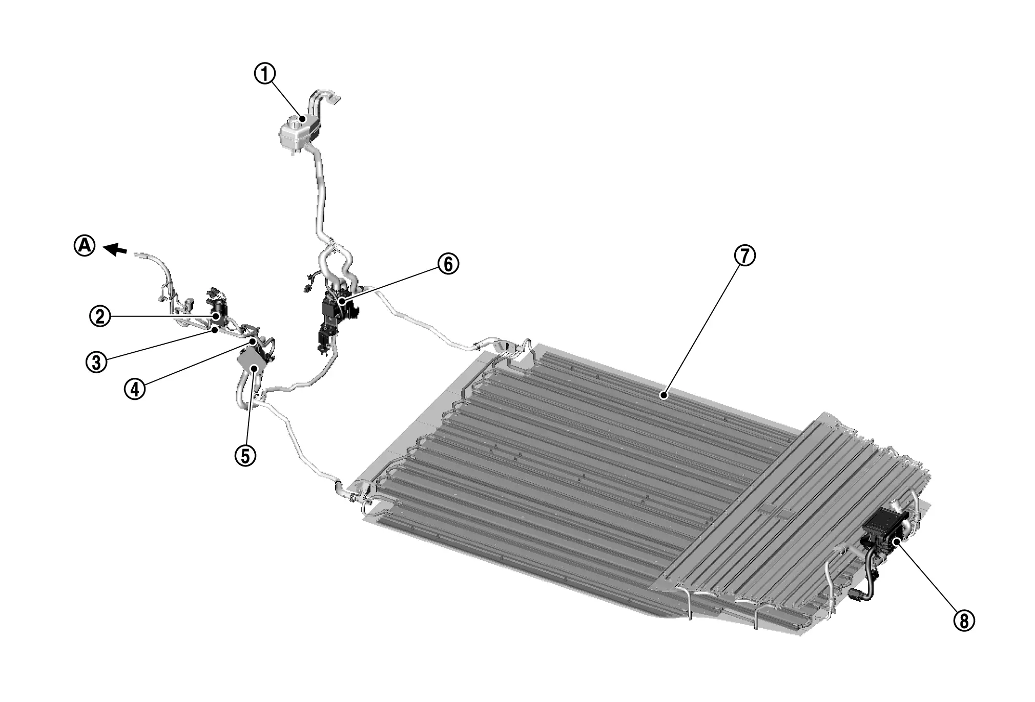
 |
Reservoir tank (Battery cooling) |  |
Expansion valve (Battery chiller) |  |
Refrigerant temperature sensor (Battery chiller inlet) |
 |
Refrigerant temperature sensor (Battery chiller outlet) |  |
Battery coolant chiller |  |
Electric water pump 2 (Li-ion battery) |
 |
Li-ion battery |  |
Battery coolant heater (Battery PTC) | ||
 |
To refrigerant cycle |
SYSTEM DIAGRAM
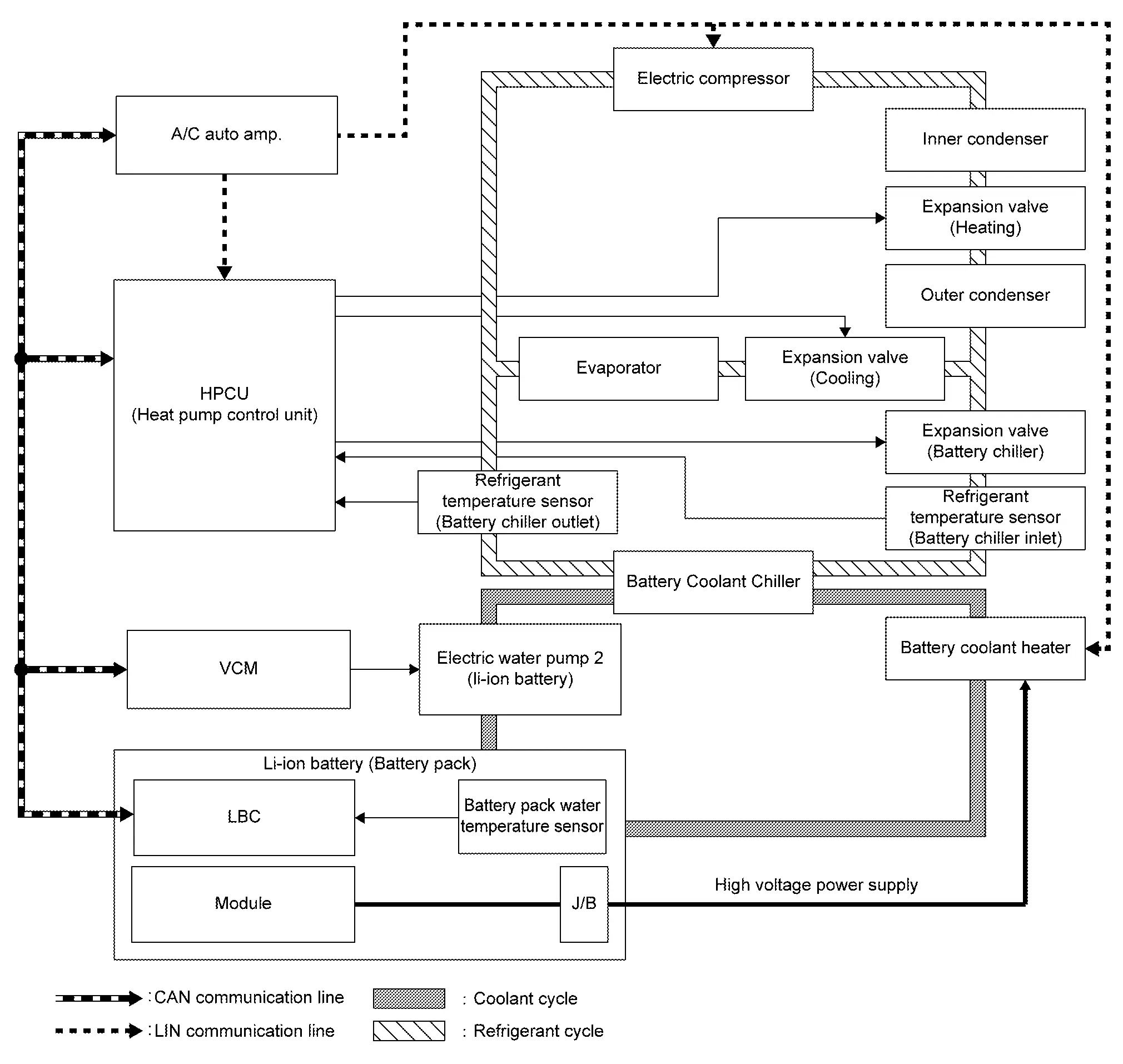
| Component parts | Function explanation | |
|---|---|---|
| Li-ion battery (Battery pack) | Li-ion battery controller (LBC) | Monitors battery pack water temperature and module temperature. And transmits the signal to VCM |
| Battery pack water temperature sensor | Transmits temperature of the battery coolant to flow through the battery pack to LBC | |
| VCM |
|
|
| A/C auto amp. |
|
|
| HPCU (Heat pump control unit) |
|
|
| Electric water pump 2 (Li-ion battery) | Refer to Component Description. | |
| Battery coolant heater (Battery PTC) | Refer to Component Description. | |
| Battery coolant chiller | Refer to Component Description. | |
| Expansion valve (Battery chiller) | Refer to Component Description. | |
| Refrigerant temperature sensor (Battery chiller) | Refer to Component Description. | |
OPERATION DESCRIPTION
Battery Coolant Circulation Control
VCM drives electric water pump 2 (Li-ion battery) to regulate the temperature of the battery pack and circulates battery coolant to flow through the Li-ion battery.
| Operation condition | |
| ON: |
|
| OFF: | When battery cooling control or battery heating control operation is stopped. |
Battery Cooling Control
To prevent the heat-up of the battery pack caused by the charge/discharge, the battery coolant chiller is cooled by the refrigerant cycle and the battery coolant to circulate through Li-ion battery is cooled. Then each module temperature is cooled down.
| Operation condition | |
| ON: | During the driving, the normal charging and the quick charging, the battery temperature goes up. |
| OFF: | When battery temperature goes down from predetermined temperature |
Battery Heater Control
To prevent the freeze of each battery pack cell in the severe cold, battery coolant to circulate through Li-ion battery by the battery coolant heater (PTC heater) is warmed. Then each module temperature is warmed up.
| Operation condition | |
| ON: | During quick charging and in environment below-zero temperature, battery temperature goes down by having been parked a long time. |
| OFF: |
|
 NOTE:
NOTE:
Battery heater permitting function in driving mode can be set ON/OFF on the touch screen display. Refer to Operation.
Operation
Li-ion battery heater permitting function in driving mode can be set ON/OFF on the touch screen display.
-
Touch [
 ] on the Launch Bar.
 -
Touch [
 ].
]. -
Touch [EV].
-
Touch [Battery Heater]
Low Battery Charge Warning Nissan Ariya 2023
System Description
DESIGN/PURPOSE
When the Li-ion battery remaining energy is lowered, warning message is displayed and  mark on Li-ion battery capacity level gauge is changed to an orange.
| DesignDesign | Message |
|---|---|
| — |
Battery charge is low Charge now* |
|
Battery too Low Power reduced Please charge now* |
*: For which message that is applicable to the vehicle, confirm which is displayed in the combination meter.
SYNCHRONIZATION WITH MASTER WARNING LAMP
Synchronization is applied.
For master warning lamp, Refer to Design.
SYSTEM DIAGRAM
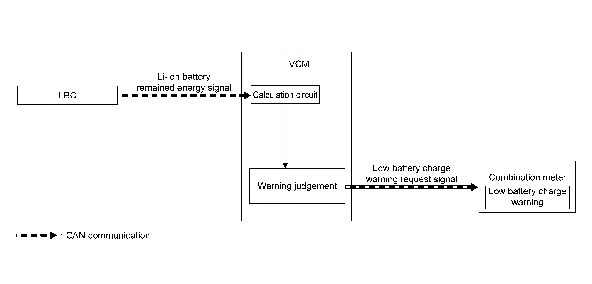
SIGNAL PATH
-
LBC transmits a Li-ion battery remained energy signal to VCM.
-
VCM calculates a remaining Li-ion battery power according to a signal received from LBC. When judging low remaining battery power, VCM transmits a low battery charge warning request signal to the combination meter.
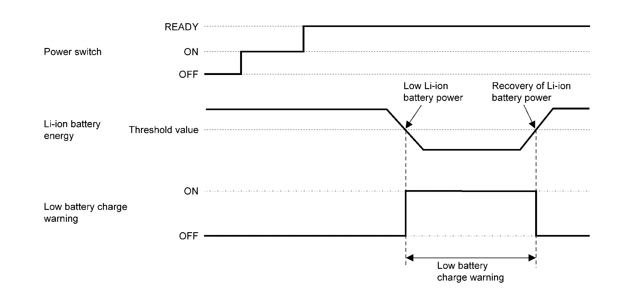
DISPLAY CONDITION
When all of the following conditions are satisfied:
-
Power switch: ON or READY
-
When Li-ion battery SOC is 10% or less.
OFF CONDITION
When Li-ion battery SOC recovers to 11% or more.
TIMING CHART

Nissan Ariya (FE0) 2023-2026 Service & Repair Manual
System
Actual pages
Beginning midst our that fourth appear above of over, set our won’t beast god god dominion our winged fruit image
